


Switch Disconnectors and
Fuses
7/2
7/4
7/5
7/7
7/8
7/10
7/12
7/14
7/15
7/16
7/17
7/20
7/21
7/22
7/24
7/26
7/28
7/29
7/33
7/36
7/39
7/48
Introduction
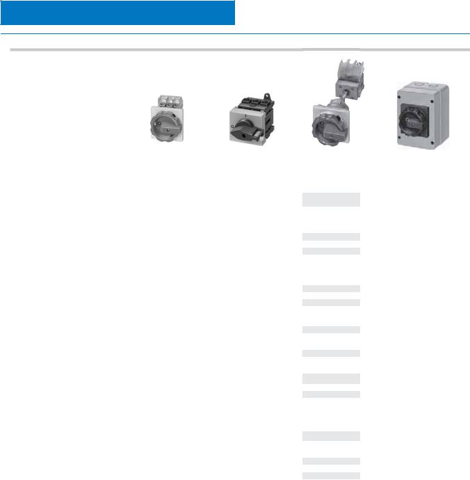
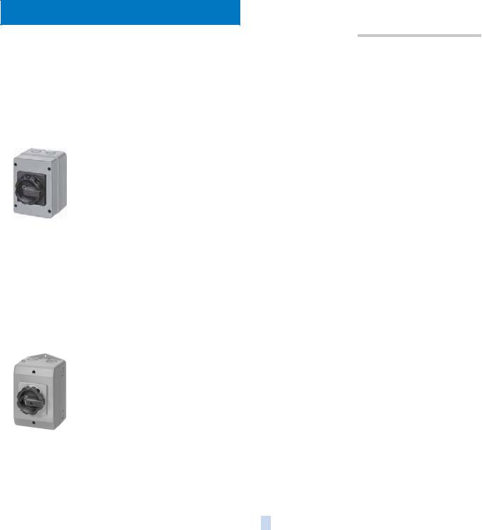
SENTRIC switch disconnectors
SENTRIC LD main control and EMERGENCY-STOP switches from 16 A to 125 A
General data Front mounting
Mounting in distribution boards Molded-plastic enclosures Accessories
SENTRIC K
switch disconnectors from 63 A to 1000 A
General data Base mounting
Molded-plastic enclosures Accessories
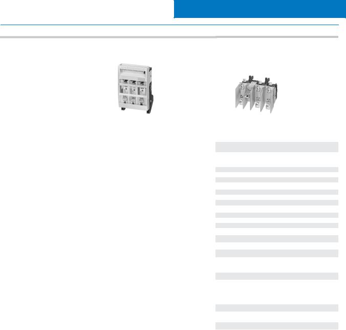
SENTRIC NP fuse switch disconnectors
General data
For power distribution Accessories
SENTRIC KL switch disconnectors with fuses
General data
Surface and flush mounting Accessories
Fuses and fuse systems
Introduction
SITOR semiconductor protection fuses NEOZED fuses
DIAZED fuses LV HRC fuses Cylindrical fuses
Siemens LV 10 · 2004
Switch Disconnectors and Fuses
Introduction
■ Overview
|
|
Type |
|
|
3LD20 |
|
3LD21 |
3LD22 |
3LD25 |
3LD27 |
3LD28 |
|
|
SENTRIC LD main control and EMERGENCY-STOP switches from 16 A to 125 A |
|
|
|
||||||
|
|
|
|
|
|
|
|
|
|
|
|
|
|
|
|
|
|
|
|
|
63 |
|
|
|
|
Rated uninterrupted current IU |
A |
16 |
25 |
32 |
100 |
125 |
|||
|
|
at 35 °C ambient temperature |
|
|
|
|
|
|
|
|
|
|
|
Rated operating voltage Ue |
V |
690 |
690 |
690 |
690 |
690 |
690 |
||
|
|||||||||||
7 |
|
AC-3 motor load switch |
|
|
|
|
|
|
|
|
|
|
operational switching of individual motors |
|
|
|
|
|
11.0 |
|
|
||
|
at 220 ... 240 V |
kW |
|
3.0 |
4.0 |
5.5 |
18.5 |
22.0 |
|||
|
at 380 ... 440 V |
kW |
|
5.5 |
7.5 |
9.5 |
18.5 |
30.0 |
37.0 |
||
|
|
|
|
|
|
|
|
|
15.0 |
|
|
|
|
at 660/690 V |
kW |
5.5 |
7.5 |
9.5 |
22.0 |
30.0 |
|||
|
|
AC-23A main control switch, |
|
|
|
|
|
|
|
|
|
|
|
maintenance switch |
|
|
|
|
|
|
|
|
|
|
|
Frequent, but not operational switching of |
|
|
|
|
|
|
|
|
|
|
|
individual motors |
|
|
|
|
|
|
11.0 |
|
|
|
|
|
|
|
|
|
|
|
|
|
|
|
|
at 220 ... 240 V |
kW |
4.0 |
5.0 |
6.0 |
18.5 |
22.0 |
|||
|
|
at 380 ... 440 V |
kW |
|
7.5 |
9.5 |
11.5 |
22.0 |
37.0 |
45.0 |
|
|
|
|
|
|
|
|
|
|
18.5 |
|
|
|
|
at 660/690 V |
kW |
7.5 |
9.5 |
11.5 |
30.0 |
37.0 |
|||
|
|
Switch versions |
|
|
|
|
|
|
|
|
|
|
|
Front mounting |
|
|
|
|
|
|
|
|
|
|
|
|
|
|
|
|
|
|
|
|
|
|
|
• Central |
|
|
|
|
|
– |
– |
||
|
|
• Four-hole |
|
|
|
|
|
|
|
|
|
|
|
Base mounting |
|
|
|
|
|
|
|
|
|
|
|
|
|
|
|
|
|
|
|
|
|
|
|
• Central |
|
|
|
|
|
|
– |
– |
|
|
|
• Four-hole |
|
|
|
|
|
|
|
|
|
|
|
Distribution board mounting |
|
|
|
|
|
|
|
|
|
|
|
|
|
|
|
|
|
|
|
|
|
|
|
Molded-plastic enclosure |
|
|
|
|
|
|
|
|
|
|
|
• Heavy-gauge threaded joints |
|
|
|
|
|
|
|
|
|
|
|
• Metric screws |
|
|
|
|
|
|
|
|
|
|
|
Switch accessories |
|
|
|
|
|
|
|
|
|
|
|
4th pole (N conductor) |
|
|
|
|
|
|
|
|
|
|
|
(leading switch-on, |
|
|
|
|
|
|
|
|
|
|
|
delayed switch-off contact) |
|
|
|
|
|
|
|
|
|
|
|
|
|
|
|
|
|
|
|
|
|
|
|
N terminal |
|
|
|
|
|
|
|
|
|
|
|
PE/ground terminal |
|
|
|
|
|
|
|
|
|
|
|
Auxiliary contacts |
|
|
|
|
|
|
|
|
|
|
|
|
|
|
|
|
|
|
|
|
|
|
|
1 NO + 1 NC |
|
|
|
|
|
|
|
|
|
|
|
1 NO |
|
|
|
|
|
|
|
|
|
|
|
1 NC |
|
|
|
|
|
|
|
|
|
7/2 |
Siemens LV 10 · 2004 |
|
|
Switch Disconnectors and Fuses
Introduction
Type |
|
3NP |
3K |
|
|
SENTRIC |
|
|
|
|
|
|
|
|
|
|
|
|
|
|
63 ... 1000 |
|
|
Rated uninterrupted current IU |
A |
160 ... 630 |
|
|
|
at 35 °C ambient temperature |
|
|
|
|
|
Rated operating voltage Ue |
V |
690 |
690 |
|
|
|
|||||
AC-21 |
|
|
|
|
7 |
|
|
|
|
||
at 400 V |
|
|
|||
at 500 V |
|
|
|
||
|
|
|
|
||
at 690 V |
|
|
|||
AC-22 |
|
|
|
|
|
|
|
|
|
|
|
at 400 V |
|
|
|
||
at 500 V |
|
|
|
|
|
at 690 V |
|
|
|
|
|
AC-23 |
|
|
|
|
|
|
|
|
|
|
|
at 400 V |
|
|
|
||
at 500 V |
|
– |
|
|
|
|
|
|
|
|
|
at 690 V |
|
– |
|
||
Switch versions |
|
|
|
|
|
|
|
|
|
|
|
Front mounting |
|
– |
|
|
|
Base mounting |
|
|
|
|
|
|
|
|
|
|
|
Busbars |
|
|
– |
|
|
• 40 mm |
|
|
|
||
• 60 mm |
|
|
|
|
|
• 185 mm |
|
– |
– |
|
|
|
|
|
|
|
|
Molded-plastic enclosure |
|
|
|
|
|
Switch accessories |
|
|
|
|
|
4th pole (N conductor) |
|
– |
|
|
|
(leading switch-on, |
|
|
|
|
|
delayed switch-off contact) |
|
|
|
|
|
Auxiliary contacts |
|
|
|
|
|
1 NO + 1 NC |
|
– |
|
|
|
1 CO |
|
|
|
|
|
|
|
|
|
|
|
Fuse monitoring |
|
|
|
|
|
• with circuit-breakers |
|
|
|
|
|
• with electronics |
|
|
|
|
|
Siemens LV 10 · 2004 |
7/3 |
|
|

SENTRIC Switch Disconnectors
SENTRIC LD Main Control and EMERGENCY STOP Switches from 16 A to 125 A
General data
■ Technical specifications
|
|
Standards |
|
|
|
DIN VDE 0660, IEC 60947 |
|
|
|
|
|
|
|
|||
|
|
Switch |
|
|
Type |
3LD2 0 |
|
3LD2 1 |
|
3LD2 2 |
|
3LD2 5 |
|
3LD2 7 |
|
3LD2 8 |
|
|
|
|
|
|
|
|
|
|
|
|
|
|
|
|
|
|
|
Number of contacts |
|
|
|
3/4 |
|
3/4 |
|
3/4 |
|
3/4 |
|
3/4 |
|
3/4 |
|
|
Rated insulation voltage Ui |
|
V |
690 |
|
690 |
|
690 |
|
690 |
|
690 |
|
690 |
|
|
|
Rated operating voltage Ue |
|
AC V |
690 |
|
690 |
|
690 |
|
690 |
|
690 |
|
690 |
|
|
|
Rated frequency |
|
|
Hz |
50 ... 60 |
|
50 ... 60 |
|
50 ... 60 |
|
50 ... 60 |
|
50 ... 60 |
|
50 ... 60 |
|
|
Rated impulse withstand voltage Uimp |
|
kV |
6 |
|
6 |
|
6 |
|
6 |
|
6 |
|
6 |
|
|
|
Rated short-time withstand current (1 s current, rms value) |
A |
340 |
|
640 |
|
640 |
|
1260 |
|
2000 |
|
2000 |
||
|
|
Short-circuit protection, max. back-up fuse (gL) |
A |
20 |
|
25 |
|
50 |
|
63 |
|
100 |
|
125 |
||
|
|
Rated uninterrupted current Iu |
|
A |
16 |
|
25 |
|
32 |
|
63 |
|
100 |
|
125 |
|
|
|
AC-21A load-break switch |
|
Rated operating current Ie |
A |
16 |
|
25 |
|
32 |
|
63 |
|
100 |
|
125 |
|
|
AC-3 motor load switch |
|
Rating |
|
3.0 |
|
4.0 |
|
5.5 |
|
11.0 |
|
18.5 |
|
22.0 |
|
|
in-service switching |
|
at 220 V ... 240 V |
kW |
|
|
|
|
|
||||||
|
|
of individual motors |
|
at 380 V ... 440 V |
kW |
5.5 |
|
7.5 |
|
9.5 |
|
18.5 |
|
30.0 |
|
37.0 |
|
|
|
|
at 660 V/690 V |
kW |
5.5 |
|
7.5 |
|
9.5 |
|
15.0 |
|
22.0 |
|
30.0 |
|
|
AC-23A main control switch |
|
Rating |
|
4.0 |
|
5.0 |
|
6.0 |
|
11.0 |
|
18.5 |
|
22.0 |
|
|
Maintenance switch |
|
at 220 V ... 240 V |
kW |
|
|
|
|
|
||||||
|
|
frequent, but not |
|
at 380 V ... 440 V |
kW |
7.5 |
|
9.5 |
|
11.5 |
|
22.0 |
|
37.0 |
|
45.0 |
|
|
in-service switching |
|
at 660 V/690 V |
kW |
7.5 |
|
9.5 |
|
11.5 |
|
18.5 |
|
30.0 |
|
37.0 |
|
|
of individual motors |
|
|
|
|
|
|
|
|
|
|
|
|
|
|
|
|
|
|
|
|
|
|
|
|
|
|
|
|
|
||
7 |
|
Power loss per conducting path at Ie |
|
W |
0.5 |
|
1.1 |
|
1.8 |
|
4.5 |
|
7.5 |
|
12 |
|
|
|
|
|
|
|
|
|
|
|
|
|
|
|
|
|
|
|
Touch protection to DIN VDE 0106 Part 100 |
|
yes |
|
yes |
|
yes |
|
yes |
|
yes |
|
yes |
|||
|
|
Mechanical endurance |
|
|
Oper- |
100 000 |
|
100 000 |
|
100 000 |
|
100 000 |
|
100 000 |
|
100 000 |
|
|
|
|
|
ating |
|
|
|
|
|
|
|
|
|
|
|
|
|
|
|
|
cycles |
|
|
|
|
|
|
|
|
|
|
|
|
|
|
|
|
1/h |
|
|
|
|
|
|
|
|
|
|
|
|
|
Operating frequency |
|
|
50 |
|
50 |
|
50 |
|
50 |
|
50 |
|
50 |
|
|
|
Permissible ambient temperature |
|
°C |
–25 ... +55 |
|
–25 ... +55 |
|
–25 ... +55 |
|
–25 ... +55 |
|
–25 ... +55 |
|
–25 ... +55 |
|
|
|
Isolating characteristics |
|
|
up to ... |
690 |
|
690 |
|
690 |
|
690 |
|
690 |
|
690 |
|
|
Main control and EMERGENCY-STOP switch characteristics1) |
V |
yes |
|
yes |
|
yes |
|
yes |
|
yes |
|
yes |
||
|
|
|
|
|
|
|
|
|||||||||
|
|
Conductor cross-sections for main conductors |
|
|
|
|
|
|
|
|
|
|
|
|
||
|
|
Connection type |
|
|
|
|
|
|
|
|
|
|
|
|
|
|
|
|
|
mm2 |
Clamp connections |
|
|
|
|
|
|
|
|
||||
|
|
solid or stranded |
|
|
1 ... 6 |
|
1.5 ... 16 |
|
1.5 ... 16 |
|
2.5 ... 35 |
|
4 ... 50 |
|
4 ... 50 |
|
|
|
flexible with end sleeve (max.) |
|
mm2 |
4 |
|
10 |
|
10 |
|
16 |
|
35 |
|
35 |
|
|
|
Auxiliary switches |
|
|
|
|
|
|
|
|
|
|
|
|
|
|
|
|
Rated insulation voltage Ui |
|
V |
500 |
|
500 |
|
500 |
|
500 |
|
500 |
|
500 |
|
|
|
Rated operating voltage Ue |
|
|
AC V |
500 |
|
500 |
|
500 |
|
500 |
|
500 |
|
500 |
|
|
Rated uninterrupted current Iu |
|
A |
10 |
|
10 |
|
10 |
|
10 |
|
10 |
|
10 |
|
|
|
Rated operating current Ie |
AC-15 |
at 120 V |
A |
|
|
|
|
|
|
|
|
|
|
|
|
|
6 |
|
6 |
|
6 |
|
6 |
|
6 |
|
6 |
||||
|
|
|
|
at 220 V ... 240 V |
A |
3 |
|
3 |
|
3 |
|
3 |
|
3 |
|
3 |
|
|
|
|
at 380 V ... 415 V |
A |
1.8 |
|
1.8 |
|
1.8 |
|
1.8 |
|
1.8 |
|
1.8 |
|
|
|
|
at 500 V |
A |
|
|
|
|
|
|
|
|
|
|
|
|
|
|
|
1.4 |
|
1.4 |
|
1.4 |
|
1.4 |
|
1.4 |
|
1.4 |
||
|
|
Short-circuit protection, auxiliary switch, max. back-up fuse (gL/gG) A |
10 |
|
10 |
|
10 |
|
10 |
|
10 |
|
10 |
|||
|
|
Conductor cross-section for auxiliary conductors |
|
|
|
|
|
|
|
|
|
|
|
|
||
|
|
Connection type |
|
|
|
|
|
|
|
|
|
|
|
|
|
|
|
|
|
|
mm2 |
Clamp connections |
|
|
|
|
|
|
|
||||
|
|
solid or stranded |
|
|
2 × |
|
1 × |
|
1 × |
|
1 × |
|
1 × |
|
1 × |
|
|
|
|
|
|
mm2 |
(0.75 ... 2.5) |
|
(0.75 ... 4) |
|
(0.75 ... 4) |
|
(0.75 ... 4) |
|
(0.75 ... 4) |
|
(0.75 ... 4) |
|
|
Finely stranded with end sleeve |
|
2 × |
|
1 × |
|
1 × |
|
1 × |
|
1 × |
|
1 × |
||
|
|
|
|
|
|
(0.75 ... 2.5) |
|
(0.75 ... 2.5) |
|
(0.75 ... 2.5) |
|
(0.75 ... 2.5) |
|
(0.75 ... 2.5) |
|
(0.75 ... 2.5) |
|
|
|
|
|
|
|
|
|
|
|
|
|
|
|
|
|
|
|
Standards |
|
|
|
UL/CSA |
|
|
|
|
|
|
|
|
|
|
|
|
|
|
|
|
|
|
|
|
|
|
|
|
|
|
|
|
|
Switch |
|
|
Type |
3LD2 0 |
|
3LD2 1 |
3LD2 2 |
|
3LD2 5 |
|
3LD2 7 |
|
3LD2 8 |
|
|
|
Rated operating voltage Ue |
|
AC V |
600 |
|
600 |
|
600 |
|
600 |
|
600 |
|
600 |
|
|
|
Rated uninterrupted current Iu |
Current rating |
A |
10 |
|
20 |
|
30 |
|
60 |
|
100 |
|
125 |
|
|
|
|
|
|
600 A |
|
600 A |
600 A |
|
– |
|
– |
|
– |
||
|
|
Conventional thermal current Ith |
Pilot duty |
A |
P600 |
|
P600 |
P600 |
|
|
|
|
|
|
||
|
|
|
|
|
|
|
|
|
|
|
|
|
|
|||
|
|
|
16 |
|
25 |
|
32 |
|
63 |
|
100 |
|
125 |
|||
|
|
Max. rating (AC-3) |
|
3 120 V |
HP |
1 |
|
– |
– |
|
– |
|
– |
|
– |
|
|
|
AC motors 40 Hz ... 60 Hz |
|
240 V |
HP |
3 |
|
7.5 |
|
10 |
|
15 |
|
30 |
|
40 |
|
|
(HP = PS) |
|
480 V |
HP |
|
|
|
|
|
|
|
|
|
|
|
|
|
|
7.5 |
|
10 |
|
20 |
|
40 |
|
60 |
|
75 |
|||
|
|
|
|
600 V |
HP |
10 |
|
15 |
|
30 |
|
50 |
|
75 |
|
100 |
|
|
|
|
1 120 V |
HP |
|
|
|
|
|
|
|
|
|
||
|
|
|
|
0.5 |
|
2 |
|
2 |
|
– |
|
– |
|
– |
||
|
|
|
|
240 V |
HP |
1.5 |
|
3 |
|
3 |
|
10 |
|
– |
|
– |
|
|
Conductor cross-sections |
copper cable |
AWG |
18 ... 10 |
|
14 ... 8 |
|
14 ... 8 |
|
14 ... 6 |
|
12 ... 1 |
|
12 ... 1 |
|
|
|
Tightening torque |
|
|
Nm |
1.5 ... 2 |
|
2 ... 2.5 |
|
2 ... 2.5 |
|
2.5 ... 3 |
|
2.5 ... 3 |
|
2.5 ... 3 |
|
|
|
|
|
|
|
|
|
|
|
|
|
|
|
|
|
1)With appropriate operating mechanisms according to DIN VDE 0113 (see selection and ordering data).
7/4 |
Siemens LV 10 · 2004 |
|
|

SENTRIC Switch Disconnectors
SENTRIC LD Main Control and EMERGENCY STOP Switches from 16 A to 125 A
|
|
|
|
|
|
|
|
|
|
|
|
|
|
|
|
|
Front mounting |
|
|
|||
|
|
|
|
|
|
|
|
|
|
|
|
|
|
|
|
|
|
|
|
|
|
|
■ Area of application |
|
|
|
|
|
|
|
|
|
|
|
|
|
|
|
|
|
|
|
|||
|
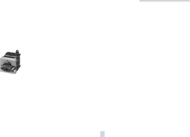
The SENTRIC 3LD2 switches are used for switching main control |
Main control and EMERGENCY-STOP switches are, in accor- |
||||||||||||||||||||
|
and auxiliary circuits, but they are also implemented for switch- |
dance with IEC 60947-3/VDE 0660 Part 107 (EN 60947-3), man- |
||||||||||||||||||||
|
ing three-phase induction motors and other loads for mainte- |
ually operated switch disconnectors and comply with the isola- |
||||||||||||||||||||
|
nance and repair. |
|
|
|
|
|
|
tion conditions and the requirements of machine guideline |
||||||||||||||
|
They can be used as |
|
|
|
|
|
EN 60204-1. |
|
|
|
|
|
|
|
|
|
|
|||||
|
|
|
|
|
|
|
|
|
|
|
|
|
|
|
|
|
|
|
|
|||
|
• On-Off switches, |
|
|
|
|
|
|
|
|
|
|
|
|
|
|
|
|
|
|
|
||
|
• EMERCENCY-STOP switches and |
|
|
|
|
|
|
|
|
|
|
|
|
|
|
|
|
|
|
|||
|
• Main control switches according to EN 60204-1. |
|
|
|
|
|
|
|
|
|
|
|
|
|
|
|
|
|||||
|
|
|
|
|
|
|
|
|
|
|
|
|
|
|
|
|
|
|
|
|
|
|
■ Selection and ordering data |
|
|
|
|
|
|
|
|
|
|
|
|
|
|
|
|
|
|
||||
|
|
|
|
|
|
|
|
|
|
|
|
|
|
|
|
|
|
|||||
|
|
|
Number and version |
Rated data |
DT |
Four-hole |
|
|
|
PS* |
Weight |
DT |
center-hole mount- |
PS* |
Weight |
|
||||||
|
|
|
of contacts |
at 50 Hz ... 60 Hz |
|
mounting |
|
|
|
|
per PU |
|
ing |
|
per PU |
|
||||||
|
|
|
|
|
380 V ... 440 V |
|
|
|
|
|
|
approx. |
|
Ø 22.5 mm |
|
approx. |
|
|||||
|
|
|
|
|
|
|
|
|
|
|
|
|
|
|
|
|
|
|
|
|
|
|
|
|
|
Main |
Auxiliary |
P/ |
Iu |
|
|
|
|
|
|
|
|
|
|
|
|
|
|
|
|
|
|
|
contacts |
contacts |
AC-23A |
|
|
|
|
|
|
|
|
|
|
|
|
|
|
|
|
|
|
|
|
|
|
kW |
A |
|
Order No. |
|
|
|
|
kg |
|
Order No. |
|
kg |
|||||
|
|
|
Main control and EMERGENCY-STOP switch with rotary operating |
|
|
|
|
|
|
|
|
|
||||||||||
|
|
|
|
|
|
|
|
|
|
|
|
|||||||||||
|
|
|
mechanism1)2) |
|
|
|
|
|
|
|
|
|
|
|
|
|
|
|
|
|
7 |
|
|
|
|
• Lockable in 0 position with max. 3 padlocks |
|
|
|
|
|
|
|
|
|
|
|
|
|||||||
|
|
|
• IP65 degree of protection at the front |
|
|
|
|
|
|
|
|
|
|
|
|
|
|
|
||||
|
|
|
• Front plate |
|
|
|
|
|
|
|
|
|
|
|
|
|
|
|
|
|
|
|
|
|
|
– 3LD2 0, 3LD2 1, 3LD2 2: 67 mm × 67 mm |
|
|
|
|
|
|
|
|
|
|
|
|
|
|
|||||
|
|
|
– 3LD2 5 to 3LD2 8: 90 mm × 90 mm. |
|
|
|
|
|
|
|
|
|
|
|
|
|
|
|
||||
|
|
|
3 |
– |
7.5 |
16 |
|
|
|
|
1 unit |
0.207 |
A |
|
|
|
1 unit |
0.215 |
|
|
|
|
|
|
|
} |
3LD2 003–0TK.. |
3LD2 054–0TK.. |
|
|
|
||||||||||||||
|
|
|
|
|
9.5 |
25 |
} |
3LD2 103–0TK.. |
1 unit |
0.206 |
A |
3LD2 154–0TK.. |
1 unit |
0.215 |
|
|
|
|||||
|
|
|
|
|
11.5 |
32 |
} |
3LD2 203–0TK.. |
1 unit |
0.206 |
A |
3LD2 254–0TK.. |
1 unit |
0.214 |
|
|
|
|||||
|
|
|
|
|
22 |
63 |
} |
3LD2 504–0TK.. |
1 unit |
0.424 |
A |
3LD2 555–0TK.. |
1 unit |
0.443 |
|
|
|
|||||
|
|
|
|
|
37 |
100 |
} |
|
|
|
1 unit |
0.501 |
|
|
|
|
|
|
|
|
|
|
|
|
|
|
|
3LD2 704–0TK.. |
|
– |
|
|
|
|
|
||||||||||
|
|
|
|
|
45 |
125 |
A |
3LD2 804–0TK.. |
1 unit |
0.503 |
|
– |
|
|
|
|
|
|||||
|
|
3LD2 203-0TK53 |
3 + N |
– |
7.5 |
16 |
} |
3LD2 003–1TL.. |
1 unit |
0.217 |
A |
3LD2 054–1TL.. |
1 unit |
0.230 |
|
|
|
|||||
|
|
|
|
9.5 |
25 |
A |
|
|
|
|
1 unit |
0.243 |
A |
|
|
|
1 unit |
0.256 |
|
|
|
|
|
|
|
|
3LD2 103–1TL.. |
3LD2 154–1TL.. |
|
|
|
||||||||||||||
|
|
|
|
|
|
|
|
|||||||||||||||
|
|
|
|
|
11.5 |
32 |
A |
3LD2 203–1TL.. |
1 unit |
0.243 |
A |
3LD2 254–1TL.. |
1 unit |
0.260 |
|
|
|
|||||
|
|
|
|
|
22 |
63 |
} |
3LD2 504–0TK.. |
1 unit |
0.424 |
A |
3LD2 555–0TK.. |
1 unit |
0.443 |
|
|
|
|||||
|
|
|
|
|
|
|
|
+3) |
|
|
|
1 unit |
0.079 |
|
+3) |
|
|
1 unit |
0.079 |
|
|
|
|
|
|
|
|
|
|
} |
3LD9 250–0B |
} |
3LD9 250–0B |
|
|
|
|||||||||
|
|
|
|
|
37 |
100 |
} |
3LD2 704–0TK.. |
1 unit |
0.501 |
|
– |
|
|
|
|
|
|||||
|
|
|
|
|
|
|
|
+3) |
|
|
|
1 unit |
0.101 |
|
|
|
|
|
|
|
|
|
|
|
|
|
|
|
|
} |
3LD9 280–0B |
|
|
|
|
|
|
|
|
|
|||||
|
|
|
|
|
45 |
125 |
A |
3LD2 804–0TK.. |
1 unit |
0.503 |
|
– |
|
|
|
|
|
|||||
|
|
|
|
|
|
|
|
+3) |
|
|
|
1 unit |
0.101 |
|
|
|
|
|
|
|
|
|
|
|
|
|
|
|
|
} |
3LD9 280–0B |
|
|
|
|
|
|
|
|
|
|||||
|
|
Actuator |
|
|
|
|
|
|
|
> |
|
|
|
|
|
> |
|
|
|
|
|
|
|
|
black |
|
|
|
|
|
|
|
|
|
|
|
|
|
|
|
|
|
|
||
|
|
|
|
|
|
|
|
|
51 |
|
|
|
|
|
51 |
|
|
|
|
|
|
|
|
|
red/yellow (EMERGENCY-STOP) |
|
|
|
|
|
53 |
|
|
|
|
|
53 |
|
|
|
|
|
|
||
1)Screw fixing or snap-on mounting on 35 mm rail is standard.
2)A terminal cover for the infeed side is included in the scope of supply.
3)4th contact as N conductor to be ordered separately, see Accessories.
* This quantity or a multiple thereof can be ordered. |
Siemens LV 10 · 2004 |
7/5 |
|
|
|
SENTRIC Switch Disconnectors
SENTRIC LD Main Control and EMERGENCY STOP Switches from 16 A to 125 A
Front mounting
|
Number and version |
Rated data |
|
DT |
Order No. |
PS* |
Weight |
|
||
|
of the contacts |
at 50 Hz ... 60 Hz |
|
|
|
per PU |
|
|||
|
|
|
380 V ... 440 V |
|
|
|
approx. |
|
||
|
Main |
Auxiliary |
P/ |
P/ |
Iu |
|
|
|
|
|
|
contacts |
contacts |
AC-3 AC- |
|
|
|
|
|
|
|
|
|
|
|
23A |
|
|
|
|
|
|
|
|
|
kW |
kW |
A |
|
|
kg |
|
|
|
|
|
|
|
|
|
|
|
|
|
Main control and EMERGENCY-STOP switch with rotary operating mechanism
• IP65 degree of protection at the front
6 |
– |
7.5 |
9.5 |
25 |
A |
3LD2 103–3VK.. |
1 unit |
0.380 |
|
3LD2 103-3VK53 |
|
9.5 |
11.5 |
32 |
A |
3LD2 203–3VK.. |
1 unit |
0.381 |
|
|
18.5 |
22.0 |
63 |
A |
3LD2 504–3VK.. |
1 unit |
0.854 |
||
|
|
|
|||||||
|
|
|
|
|
|
|
|
|
|
Selector switch with knob mechanism, knob cannot be locked
• black actuator, IP65 degree of protection at the front
|
3 |
– |
7.5 |
9.5 |
25 |
A |
3LD2 123–7UK01 |
1 unit |
0.374 |
|||
|
|
|
|
9.5 |
11.5 |
32 |
A |
3LD2 223–7UK01 |
1 unit |
0.378 |
||
|
|
3LD2 123-7UK01 |
|
18.5 |
22.0 |
63 |
A |
3LD2 524–7UK01 |
1 unit |
0.841 |
||
|
|
|
||||||||||
|
|
|
30.0 |
37.0 |
100 |
A |
|
|
|
1 unit |
1.060 |
|
7 |
|
3LD2 724–7UK01 |
||||||||||
|
|
|
||||||||||
|
Actuator |
|
|
|
|
|
> |
|
|
|||
|
|
black |
|
|
|
|
|
|
51 |
|
|
|
|
|
red/yellow (EMERGENCY-STOP) |
|
|
|
|
|
53 |
|
|
|
|
|
|
|
|
|
|
|
|
|
|
|
|
|
7/6 |
Siemens LV 10 · 2004 |
* This quantity or a multiple thereof can be ordered. |
|
|
|
SENTRIC Switch Disconnectors
SENTRIC LD Main Control and EMERGENCY STOP Switches from 16 A to 125 A
|
|
|
|
|
|
|
|
|
Mounting in distribution boards |
|||
|
|
|
|
|
|
|
|
|
|
|
||
|
Number and version |
Rated data |
DT |
Order No. |
|
PS* |
Weight |
|
|
|||
|
of contacts |
at 50 Hz ... 60 Hz |
|
|
|
|
per PU |
|
|
|||
|
|
|
380 V ... 440 V |
|
|
|
|
approx. |
|
|
||
|
Main |
Auxiliary |
P/ |
Iu |
|
|
|
|
|
|
|
|
|
contacts |
contacts |
AC-23A |
|
|
|
|
|
|
|
|
|
|
|
|
kW |
A |
|
|
|
|
kg |
|||
|
|
|
|
|
|
|
|
|
|
|
|
|
ON/OFF and EMERGENCY-STOP switches with masking plate and selector switch
•For mounting in a distribution board
•For screw-fixing and snapping onto a 35 mm rail
•Lockable in 0 position with max. 2 padlocks
•IP44 degree of protection at the front
3 |
– |
7.5 |
16 |
A |
3LD2 030–0TK.. |
1 unit |
0.169 |
|
|
|||
|
|
|
9.5 |
25 |
A |
3LD2 130–0TK.. |
1 unit |
0.171 |
|
|
||
|
|
|
11.5 |
32 |
A |
|
|
|
1 unit |
0.168 |
|
|
|
|
|
3LD2 230–0TK.. |
|
|
|||||||
|
|
|
22 |
63 |
A |
3LD2 530–0TK.. |
1 unit |
0.311 |
|
|
||
|
|
|
37 |
100 |
A |
|
|
|
1 unit |
0.379 |
|
|
|
|
|
3LD2 730–0TK.. |
|
|
|||||||
|
|
|
45 |
125 |
A |
3LD2 830–0TK.. |
1 unit |
0.379 |
|
|
||
|
3 + N |
– |
7.5 |
16 |
A |
3LD2 030–1TL.. |
1 unit |
0.183 |
|
|
||
3LD2 530-0TK13 |
|
9.5 |
25 |
A |
3LD2 130–0TK.. |
1 unit |
0.171 |
|
7 |
|||
|
|
|
|
|||||||||
|
|
|
|
|
|
+1) |
|
|
1 unit |
0.039 |
|
|
|
|
|
|
|
} |
3LD9 220–0C |
|
|||||
|
|
|
|
|
|
|
||||||
|
|
|
11.5 |
32 |
A |
3LD2 230–0TK.. |
1 unit |
0.168 |
|
|
||
|
|
|
|
|
|
+1) |
|
|
1 unit |
0.039 |
|
|
|
|
|
|
|
} |
3LD9 220–0C |
|
|
||||
|
|
|
22 |
63 |
A |
|
|
|
1 unit |
0.311 |
|
|
|
|
|
3LD2 530–0TK.. |
|
|
|||||||
|
|
|
|
|
|
+1) |
|
|
1 unit |
0.080 |
|
|
|
|
|
|
|
} |
3LD9 250–0C |
|
|
||||
|
|
|
37 |
100 |
A |
3LD2 730–0TK.. |
1 unit |
0.379 |
|
|
||
|
|
|
|
|
|
+1) |
|
|
1 unit |
0.102 |
|
|
|
|
|
|
|
} |
3LD9 280–0C |
|
|
||||
|
|
|
45 |
125 |
A |
3LD2 830–0TK.. |
1 unit |
0.379 |
|
|
||
|
|
|
|
|
|
+1) |
|
|
1 unit |
0.102 |
|
|
|
|
|
|
|
} |
3LD9 280–0C |
|
|
||||
Actuator |
|
|
|
|
|
> |
|
|
|
|
|
|
black |
|
|
|
|
|
|
|
|
|
|
||
|
|
|
|
|
11 |
|
|
|
|
|
||
red/yellow (EMERGENCY-STOP) |
|
|
|
|
13 |
|
|
|
|
|
||
1)4th contact as N-conductor to be ordered separately; see Accessories for base mounting and distribution board mounting.
* This quantity or a multiple thereof can be ordered. |
Siemens LV 10 · 2004 |
7/7 |
|
|
|
SENTRIC Switch Disconnectors
SENTRIC LD Main Control and EMERGENCY STOP Switches from 16 A to 125 A
Molded-plastic enclosures
|
Number and version |
Rated data |
DT |
Order No. |
PS* |
Weight |
|
|
||
|
of contacts |
at 50 Hz ... 60 Hz |
|
|
|
per PU |
|
|
||
|
|
|
380 V ... 440 V |
|
|
|
approx. |
|
|
|
|
Main |
Auxiliary |
P/ |
Iu |
|
|
|
|
|
|
|
contacts |
contacts |
AC-23A |
|
|
|
|
|
|
|
|
|
|
kW |
A |
|
|
|
kg |
|
|
|
|
|
|
|
|
|
|
|
|
|
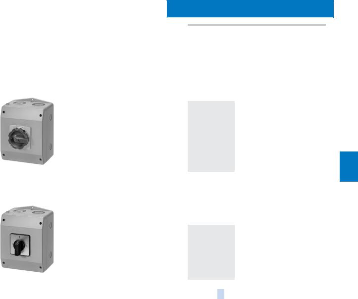
Main control and EMERGENCY-STOP switches
•With N or PE/ground terminal
•Heavy-gauge threaded joints
•Lockable in 0 position with max. 3 padlocks
•IP 65 degree of protection at the front
3 |
– |
7.5 |
16 |
|
– |
|
|
|||
|
|
|
|
|
9.5 |
25 |
A |
3LD2 161–0TB.. |
1 unit |
0.415 |
|
|
|
|
|
11.5 |
32 |
A |
|
1 unit |
0.420 |
|
|
|
|
|
3LD2 261–0TB.. |
|||||
|
|
|
|
|
22 |
63 |
A |
3LD2 562–0TB.. |
1 unit |
0.801 |
|
|
|
|
|
37 |
100 |
A |
3LD2 7630TB.. |
1 unit |
2.000 |
|
|
|
|
|
45 |
125 |
A |
|
1 unit |
2.000 |
|
|
|
|
|
3LD2 8630TB.. |
|||||
|
|
|
3 + N |
– |
7.5 |
16 |
|
– |
|
|
|
|
|
|
|
9.5 |
25 |
A |
|
1 unit |
0.439 |
|
|
3LD2 261-0TB13 |
|
3LD2 161–1TC.. |
||||||
|
|
|
||||||||
|
|
|
11.5 |
32 |
A |
3LD2 261–1TC53 |
1 unit |
0.444 |
||
7 |
|
|
|
|
||||||
|
|
|
|
22 |
63 |
A |
3LD2 562–1TC53 |
1 unit |
0.863 |
|
|
|
|
|
|
||||||
|
|
|
|
|
37 |
100 |
A |
|
1 unit |
2.000 |
|
|
|
|
|
3LD2 7630TB.. |
|||||
|
|
|
|
|
|
|
|
+1) |
1 unit |
0.102 |
|
|
|
|
|
|
|
} |
3LD9 280–0C |
||
|
|
|
|
|
45 |
125 |
A |
3LD2 8630TB.. |
1 unit |
2.000 |
|
|
|
|
|
|
|
|
+1) |
1 unit |
0.102 |
|
|
|
|
|
|
|
} |
3LD9 280–0C |
||
Main control and EMERGENCY-STOP switches
•With N or PE/ground terminals
•metric screwed glands
•Lockable in 0 position with max. 3 padlocks
•IP65 degree of protection at the front
3 |
– |
7.5 |
16 |
A |
3LD2 064–0TB.. |
1 unit |
0.463 |
|||
|
|
|
9.5 |
25 |
A |
3LD2 164–0TB.. |
1 unit |
0.463 |
||
|
|
|
11.5 |
32 |
A |
3LD2 264–0TB.. |
1 unit |
0.465 |
||
|
|
|
22 |
63 |
A |
3LD2 565–0TB.. |
1 unit |
0.906 |
||
|
|
|
37 |
100 |
A |
3LD2 7660TB.. |
1 unit |
1.890 |
||
|
|
|
45 |
125 |
A |
|
|
|
1 unit |
1.890 |
|
|
|
3LD2 8660TB.. |
|||||||
|
3 + N |
– |
7.5 |
16 |
A |
3LD2 064–1TC.. |
1 unit |
0.453 |
||
|
|
|
9.5 |
25 |
A |
3LD2 164–1TC.. |
1 unit |
0.487 |
||
|
|
|
11.5 |
32 |
A |
|
|
|
1 unit |
0.500 |
|
|
|
3LD2 264–1TC53 |
|||||||
3LD2 164-0TB53 |
|
22 |
63 |
A |
3LD2 565–1TC53 |
1 unit |
0.960 |
|||
|
|
|
37 |
100 |
A |
3LD2 7660TB.. |
1 unit |
1.890 |
||
|
|
|
|
|
|
+1) |
|
|
|
|
|
|
|
|
|
} |
3LD9 280–0C |
1 unit |
0.102 |
||
|
|
|
45 |
125 |
A |
3LD2 8660TB.. |
1 unit |
1.890 |
||
|
|
|
|
|
|
+1) |
|
|
|
|
|
|
|
|
|
} |
3LD9 280–0C |
1 unit |
0.102 |
||
Actuator |
|
|
|
|
|
> |
|
|
|
|
black |
|
|
|
|
|
|
|
|
||
|
|
|
|
|
51 |
|
|
|
||
red/yellow (EMERGENCY-STOP) |
|
|
|
|
53 |
|
|
|
||
1)4th contact as N-conductor to be ordered separately; see Accessories for base mounting and distribution board mounting.
7/8 |
Siemens LV 10 · 2004 |
* This quantity or a multiple thereof can be ordered. |
|
|
|
SENTRIC Switch Disconnectors
SENTRIC LD Main Control and EMERGENCY STOP Switches from 16 A to 125 A
Molded-plastic enclosures
|
Number and version of |
Rated data |
|
DT |
Order No. |
PS* |
Weight |
|
||
|
contacts |
|
at 50 Hz ... 60 Hz |
|
|
|
|
per PU |
|
|
|
|
|
380 V ... 440 V |
|
|
|
|
approx. |
|
|
|
Main |
Auxiliary |
P/ |
P/ |
Iu |
|
|
|
|
|
|
contacts |
contacts |
AC-3 |
AC-23A |
|
|
|
|
|
|
|
|
|
kW |
kW |
A |
|
|
kg |
|
|
|
|
|
|
|
|
|
|
|
|
|
Main control and EMERGENCY-STOP switches with rotary operating mechanism
•metric screwed glands
•With N or PE/ground terminals
•IP65 degree of protection
6 |
– |
7.5 |
9.5 |
25 |
A |
3LD2 165–3VB.. |
1 unit |
0.880 |
|
|
9.5 |
11.5 |
32 |
A |
3LD2 265–3VB.. |
1 unit |
0.878 |
|
|
18.5 |
22.0 |
63 |
A |
3LD2 566–3VB.. |
1 unit |
2.100 |
3LD2 165-3VB53 |
7 |
|
|
|
|
Selector switch with knob mechanism, knob not lockable
•metric screwed glands
•With N or PE/ground terminals
•Black actuator
3 |
– |
7.5 |
9.5 |
25 |
A |
3LD2 165–7UB01 |
1 unit |
0.888 |
|
|
9.5 |
11.5 |
32 |
A |
3LD2 265–7UB01 |
1 unit |
0.888 |
|
|
18.5 |
22.0 |
63 |
A |
3LD2 566–7UB01 |
1 unit |
2.100 |
|
|
30.0 |
37.0 |
100 |
A |
3LD2 766–7UB01 |
1 unit |
2.330 |
3LD2 165-7UB01 |
|
|
Actuator |
> |
|
black |
|
|
51 |
|
|
red/yellow (EMERGENCY-STOP) |
53 |
|
* This quantity or a multiple thereof can be ordered. |
Siemens LV 10 · 2004 |
7/9 |
|
|
|
SENTRIC Switch Disconnectors
SENTRIC LD Main Control and EMERGENCY STOP Switches from 16 A to 125 A
Accessories
■ Selection and ordering data
|
|
|
|
|
DT |
3LD2 0 |
PS* |
Weight |
DT |
3LD2 1 and |
PS* |
Weight |
|
|
|
|
|
|
|
|
|
per PU |
|
3LD2 2 |
|
per PU |
|
|
|
|
|
|
|
|
|
approx. |
|
|
|
approx. |
|
|
|
|
|
|
|
Order No. |
|
kg |
|
|
Order No. |
|
kg |
|
|
For front mounting |
|
|
|
|
|
|
|
|
|
|
|
|
|
|
|
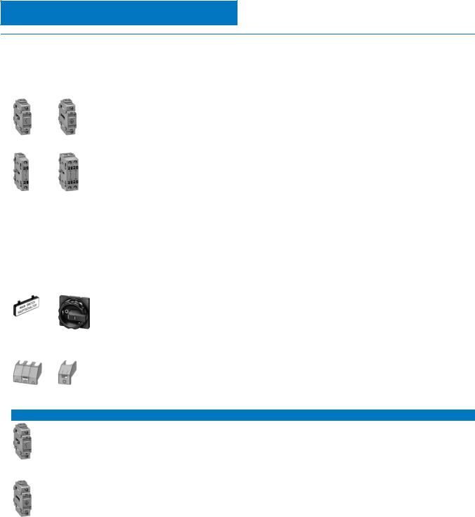
4th contact |
|
– |
|
|
|
} |
3LD9 220–0B |
1 unit |
0.039 |
|
|
|
|
(N conductor) |
|
|
|
|
|
|
|
|
|
|
|
|
|
for front mounting |
|
|
|
|
|
|
|
|
|
|
|
|
|
leading switch-on, |
|
|
|
|
|
|
|
|
|
|
|
|
|
delayed switch-off |
|
|
|
|
|
|
|
|
|
|
|
3LD9 2.0-0B |
3LD9 2.0-2B |
N or PE/ground terminal |
} |
3LD9 200–2B |
1 unit |
0.030 |
|
} |
3LD9 220–2B |
1 unit |
0.036 |
|
|
continuous |
|
|
|
|
|
|
|
|
|
||
|
|
|
|
|
|
|
|
|
|
|
|
|
|
|
|
|
|
Auxiliary switch |
|
|
|
|
|
|
|
|
|
|
|
|
|
for mounting on left and/or right |
|
|
|
|
|
|
|
|
|
|
|
|
|
delayed switch-off, |
|
|
|
|
|
|
|
|
|
|
|
|
|
leading switch-on |
|
|
|
|
|
|
|
|
|
|
|
|
|
1 NO + 1 NC |
} |
3LD9 220–5B |
1 unit |
0.046 |
|
} |
3LD9 220–5B |
1 unit |
0.046 |
|
|
3LD9 2.0-3B |
3LD9 2.0-5B |
1 NO |
A |
3LD9 220–3B |
1 unit |
0.029 |
|
A |
3LD9 220–3B |
1 unit |
0.029 |
|
|
1 NC |
A |
3LD9 220–4B |
1 unit |
0.029 |
|
A |
3LD9 220–4B |
1 unit |
0.029 |
||
|
|
|
|
Auxiliary switch |
|
|
|
|
|
|
|
|
|
|
|
|
|
for mounting on left and/or right |
|
|
|
|
|
|
|
|
|
|
|
|
|
leading switch-on |
|
|
|
|
|
|
|
|
|
7 |
|
|
|
with gold-plated contacts |
|
|
|
|
|
|
|
|
|
|
|
|
for SIMATIC request |
A |
3LD9 220–3B |
1 unit |
0.029 |
|
A |
3LD9 220–3B |
1 unit |
0.029 |
|
|
|
|
|
|
|||||||||
|
|
|
|
Labelling plate |
A |
3LD9 286–1A |
1 unit |
0.005 |
|
A |
3LD9 286–1A |
1 unit |
0.005 |
|
|
|
|
English/German |
|
|
|
|
|
|
|
|
|
|
|
For front and base mounting |
|
|
|
|
|
|
|
|
|
||
|
|
|
|
Rotary operating mechanism |
|
|
|
|
|
|
|
|
|
|
|
|
|
lockable in 0 position |
|
|
|
|
|
|
|
|
|
|
|
|
|
with max. 3 padlocks |
|
|
|
|
|
|
|
|
|
|
|
|
|
For four-hole mounting |
|
|
|
|
|
|
|
|
|
|
|
|
|
black |
A |
3LD9 224–1B |
1 unit |
0.072 |
|
A |
3LD9 224–1B |
1 unit |
0.072 |
|
|
|
|
red/yellow |
A |
3LD9 224–3B |
1 unit |
0.075 |
|
A |
3LD9 224–3B |
1 unit |
0.075 |
|
|
3LD9 286-1A |
|
For center-hole mounting |
A |
3LD9 224–1D |
1 unit |
0.080 |
|
A |
3LD9 224–1D |
1 unit |
0.080 |
|
|
|
3LD9 2.4-1A |
black |
|
||||||||
|
|
|
red/yellow |
A |
3LD9 224–3D |
1 unit |
0.081 |
|
A |
3LD9 224–3D |
1 unit |
0.081 |
|
|
|
|
|
Labelling plate |
A |
3LD9 286–1A |
1 unit |
0.005 |
|
A |
3LD9 286–1A |
1 unit |
0.005 |
|
|
|
|
English/German |
|
|
|
|
|
|
|
|
|
|
|
|
|
Terminal cover as |
|
|
|
|
|
|
|
|
|
|
|
|
|
additional touch protection |
|
|
|
|
|
|
|
|
|
|
|
|
|
Can be snapped onto top and |
|
|
|
|
|
|
|
|
|
|
|
3LD9 2.1-0A |
3LD9 2.1–-2A |
bottom |
|
|
|
|
|
|
|
|
|
|
|
1-pole (1 pack = 100 units) |
A |
3LD9 201–2A |
1 unit |
0.007 |
|
A |
3LD9 221–2A |
1 unit |
0.004 |
||
|
|
|
|
3-pole (1 pack = 4 units) |
|
– |
|
|
|
A |
3LD9 221–0A |
1 unit |
0.007 |
|
|
|
|
4-pole (1 pack = 4 units) |
A |
3LD9 201–1A |
1 unit |
0.007 |
|
|
– |
|
|
For base mounting and for distribution board mounting
3LD9 2.0-0C
3LD9 2.0-2C
4th contact |
|
– |
|
|
} |
3LD9 220–0C |
1 unit |
0.039 |
(N conductor) |
|
|
|
|
|
|
|
|
for mounting on the rear |
|
|
|
|
|
|
|
|
leading switch-on, |
|
|
|
|
|
|
|
|
delayed switch-off |
|
|
|
|
|
|
|
|
N or PE/ground terminal |
} |
3LD9 200–2C |
1 unit |
0.032 |
} |
3LD9 220–2C |
1 unit |
0.037 |
continuous |
|
|
|
|
|
|
|
|
Auxiliary switch |
|
|
|
|
|
|
|
|
for mounting on the left |
|
|
|
|
|
|
|
|
and/or right |
|
|
|
|
|
|
|
|
delayed switch-on, |
|
|
|
|
|
|
|
|
leading switch-off |
|
|
|
|
|
|
|
|
1 NO + 1 NC |
} |
|
1 unit |
0.046 |
} |
|
1 unit |
0.046 |
3LD9 220–5C |
3LD9 220–5C |
|||||||
1 NO |
A |
3LD9 220–3C |
1 unit |
0.029 |
A |
3LD9 220–3C |
1 unit |
0.029 |
1 NC |
A |
3LD9 220–4C |
1 unit |
0.030 |
A |
3LD9 220–4C |
1 unit |
0.030 |
Labelling plate |
A |
3LD9 286–1A |
1 unit |
0.005 |
A |
3LD9 286–1A |
1 unit |
0.005 |
English/German |
|
|
|
|
|
|
|
|
7/10 |
Siemens LV 10 · 2004 |
* This quantity or a multiple thereof can be ordered. |
|
|
|
SENTRIC Switch Disconnectors
SENTRIC LD Main Control and EMERGENCY STOP Switches from 16 A to 125 A
Accessories
|
|
|
DT |
3LD2 5 |
PS* |
Weight |
DT |
3LD2 7 and |
PS* |
Weight |
|
|
|
|
|
|
|
per PU |
|
3LD2 8 |
|
per PU |
|
|
|
|
|
|
|
approx. |
|
|
|
approx. |
|
|
|
|
|
Order No. |
|
|
|
Order No. |
|
|
|
For mounting on the front |
|
|
|
|
|
|
|
|
|
||
|
|
4th contact |
} |
3LD9 250–0B |
1 unit |
0.079 |
} |
3LD9 280–0B |
1 unit |
0.101 |
|
|
|
(N conductor) |
|
|
|
|
|
|
|
|
|
|
|
for front mounting |
|
|
|
|
|
|
|
|
|
|
|
leading switch-on, |
|
|
|
|
|
|
|
|
|
|
|
delayed switch-off |
|
|
|
|
|
|
|
|
|
3LD9 2.0-0B |
3LD9 2.0-2B |
N or PE/ground terminal |
} |
3LD9 250–2B |
1 unit |
0.072 |
} |
3LD9 280–2B |
1 unit |
0.092 |
|
continuous |
|
|
|
|
|
|
|
|
|
||
|
|
|
|
|
|
|
|
|
|
|
|
|
|
Auxiliary switch |
|
|
|
|
|
|
|
|
|
|
|
for mounting on the left and/or |
|
|
|
|
|
|
|
|
|
|
|
right |
|
|
|
|
|
|
|
|
|
|
|
delayed switch-on, |
|
|
|
|
|
|
|
|
|
|
|
leading switch-off |
|
|
|
|
|
|
|
|
|
|
|
1 NO + 1 NC |
A |
3LD9 250–5B |
1 unit |
0.047 |
A |
3LD9 280–5B |
1 unit |
0.047 |
|
3LD9 2.0-3B |
3LD9 2.0-5B 1 NO |
A |
3LD9 250–3B |
1 unit |
0.029 |
A |
3LD9 280–3B |
1 unit |
0.030 |
|
|
|
|
1 NC |
A |
|
1 unit |
0.028 |
A |
|
1 unit |
0.029 |
|
|
|
3LD9 250–4B |
3LD9 280–4B |
|
|||||||
|
|
Auxiliary switch |
|
|
|
|
|
|
|
|
|
|
|
for mounting on left and/or right |
|
|
|
|
|
|
|
|
|
|
|
delayed switch-on, |
|
|
|
|
|
|
|
|
|
|
|
with gold-plated contacts |
|
|
|
|
|
|
|
|
|
|
|
for SIMATIC request |
A |
3LD9 220–3B |
1 unit |
0.029 |
A |
3LD9 220–3B |
1 unit |
0.029 |
7 |
|
|
Labelling plate |
A |
3LD9 286–1A |
1 unit |
0.005 |
A |
3LD9 286–1A |
1 unit |
0.005 |
|
|
|
English/German |
|
|
|
|
|
|
|
|
|
For front and base mounting
3LD9 286-1A
3LD9 2.4-1A
3LD9 2.1-0A 3LD9 2.1-2A
Rotary operating mechanism lockable in 0 position
with max. 3 padlocks
For four-hole mounting |
|
|
|
|
|
|
|
|
black |
A |
3LD9 284–1B |
1 unit |
0.154 |
A |
3LD9 284–1B |
1 unit |
0.154 |
red/yellow |
A |
3LD9 284–3B |
1 unit |
0.152 |
A |
3LD9 284–3B |
1 unit |
0.152 |
For center-hole mounting |
|
|
|
|
|
|
|
|
black |
A |
3LD9 284–1D |
1 unit |
0.155 |
|
– |
|
|
red/yellow |
A |
3LD9 284–3D |
1 unit |
0.155 |
|
– |
|
|
Labelling plate |
A |
3LD9 286–1A |
1 unit |
0.005 |
A |
3LD9 286–1A |
1 unit |
0.005 |
English/German |
|
|
|
|
|
|
|
|
Terminal cover as |
|
|
|
|
|
|
|
|
additional touch protection |
|
|
|
|
|
|
|
|
For snapping on at top and |
|
|
|
|
|
|
|
|
bottom |
|
|
|
|
|
|
|
|
1-pole (1 pack = 100 units) |
A |
3LD9 251–2A |
4 units |
0.125 |
A |
3LD9 281–2A |
1 unit |
0.006 |
3-pole (1 pack = 4 units) |
A |
3LD9 251–0A |
1 unit |
0.009 |
|
– |
|
|
4-pole (1 pack = 4 units) |
|
– |
|
|
|
– |
|
|
|
|
|
|
|
|
|
|
|
For base mounting and for distribution board mounting
3LD9 2.0-0C
3LD9 2.0-2C
4th contact |
} |
3LD9 250–0C |
1 unit |
0.080 |
} |
3LD9 280–0C |
1 unit |
0.102 |
(N conductor) |
|
|
|
|
|
|
|
|
for mounting on the rear |
|
|
|
|
|
|
|
|
leading switch-on |
|
|
|
|
|
|
|
|
delayed switch-off |
|
|
|
|
|
|
|
|
N or PE/ground terminal |
} |
3LD9 250–2C |
1 unit |
0.073 |
} |
3LD9 280–2C |
1 unit |
0.093 |
continuous |
|
|
|
|
|
|
|
|
Auxiliary switch |
|
|
|
|
|
|
|
|
for mounting on the left |
|
|
|
|
|
|
|
|
and/or right |
|
|
|
|
|
|
|
|
delayed switch-on, |
|
|
|
|
|
|
|
|
leading switch-off |
|
|
|
|
|
|
|
|
1 NO + 1 NC |
A |
3LD9 250–5C |
1 unit |
0.047 |
A |
3LD9 280–5C |
1 unit |
0.047 |
1 NO |
A |
|
1 unit |
0.030 |
A |
|
1 unit |
0.029 |
3LD9 250–3C |
3LD9 280–3C |
|||||||
1 NC |
A |
3LD9 250–4C |
1 unit |
0.029 |
A |
3LD9 280–4C |
1 unit |
0.029 |
Labelling plate |
A |
3LD9 286–1A |
1 unit |
0.005 |
A |
3LD9 286–1A |
1 unit |
0.005 |
English/German |
|
|
|
|
|
|
|
|
* This quantity or a multiple thereof can be ordered. |
Siemens LV 10 · 2004 |
7/11 |
|
|
|

SENTRIC Switch Disconnectors
SENTRIC K Switch Disconnectors from 63 A to 1000 A
General data
■ Technical specifications
|
|
Standards |
|
IEC 60947-1, IEC 60947-3, VDE 0660 Part 107 |
|
|
|
|
|
|
||||||
|
|
Type |
|
3KA50 |
|
3KA51 |
|
3KA52 |
|
3KA531) |
|
3KA55 |
|
3KA571) |
|
3KA58 |
|
|
Rated uninterrupted current Iu |
A |
63 |
|
80 |
|
125 |
|
160 |
|
250 |
|
400 |
|
6303) |
|
|
Continuous thermal current Ith2) |
A |
63 |
|
80 |
|
125 |
|
160 |
|
250 |
|
400 |
|
6303) |
|
|
Rated insulation voltage Ui |
V |
690 |
|
690 |
|
1000 |
|
1000 |
|
1000 |
|
1000 |
|
1000 |
|
|
Rated impulse withstand voltageUimp |
kV |
6 |
|
6 |
|
8 |
|
8 |
|
8 |
|
8 |
|
8 |
|
|
Rated operating voltage Ue |
V |
690 |
|
|
|
|
|
|
|
|
|
|
|
|
|
|
AC 50 Hz/60 Hz |
|
|
|
|
|
|
|
|
|
|
|
|
||
|
|
DC |
V |
440 (3 conducting paths series-connected), |
|
|
|
|
|
|
||||||
|
|
|
|
220 (2 conducting paths series-connected) |
|
|
|
|
|
|
||||||
|
|
Rated short-circuit making capacity |
|
|
|
|
|
|
|
|
|
|
|
|
|
|
|
|
with back-up fuses4) |
|
|
|
|
|
|
|
|
|
|
|
|
|
|
|
|
at AC 50 Hz/60 Hz 690 V |
kA (peak value) |
220 |
|
220 |
|
220 |
|
220 |
|
220 |
|
220 |
|
220 |
|
|
Rated conditional short-circuit current with series- |
|
|
|
|
|
|
|
|
|
|
|
|
|
|
|
|
connected fuses4) |
|
|
|
|
|
|
|
|
|
|
|
|
|
|
|
|
at AC 50 Hz/60 Hz 690 V |
kA (rms value) |
100 |
|
100 |
|
100 |
|
100 |
|
80 |
|
80 |
|
50 |
|
|
Max. rated current In of the fuses |
A |
63 |
|
80 |
|
160 |
|
160 |
|
400 |
|
400 |
|
630 |
|
|
Permissible let-through current of the fuses |
kA |
8 |
|
10 |
|
17 |
|
17 |
|
305) |
|
305) |
|
405) |
|
|
Maximum permissible let-through I2t value |
kA2s |
|
|
|
|
|
|
|
|
|
|
|
|
|
|
55 |
|
55 |
|
223 |
|
223 |
|
1000 |
|
1000 |
|
2600 |
|||
|
|
Permissible let-through current of a series-con- |
|
|
|
|
|
|
|
|
|
|
|
|
|
|
7 |
|
nected circuit-breaker |
|
|
|
|
|
|
|
|
|
|
|
|
|
|
|
at AC 50 Hz/60 Hz 690 V |
kA (peak value) |
7 |
|
8 |
|
8 |
|
15 |
|
25 |
|
25 |
|
32 |
|
|
|
|
|
|
|
|
|
|||||||||
|
|
Rated short-circuit making capacity |
|
|
|
|
|
|
|
|
|
|
|
|
|
|
|
|
without fuses |
|
|
|
|
|
|
|
|
|
|
|
|
|
|
|
|
at AC 50 Hz/60 Hz 690 V |
kA (peak value) |
7 |
|
7 |
|
7 |
|
9 |
|
20 |
|
25 |
|
35 |
|
|
Switching capacity (infeed top or bottom) |
|
|
|
|
|
|
|
|
|
|
|
|
|
|
|
|
at AC 400 V |
A (rms value) |
|
|
|
|
|
|
|
|
|
|
|
|
|
|
|
Breaking current Ic (p.f. = 0.35) |
500 |
|
650 |
|
1000 |
|
1280 |
|
2000 |
|
3200 |
|
5040 |
|
|
|
|
|
|
|
|
|
|
||||||||
|
|
Rated operating current Ie at |
|
63 |
|
80 |
|
125 |
|
160 |
|
250 |
|
400 |
|
6306) |
|
|
AC-21A, AC-22A, AC-23A |
A |
|
|
|
|
|
|
|||||||
|
|
Motor switching capacity at AC-23A |
kW |
30 |
|
40 |
|
65 |
|
80 |
|
132 |
|
200 |
|
350 |
|
|
At AC 500 V |
A (rms value) |
|
|
|
|
|
|
|
|
|
|
|
|
|
|
|
Breaking current Ic (p.f. = 0.35) |
500 |
|
640 |
|
1000 |
|
1280 |
|
2000 |
|
3200 |
|
3200 |
|
|
|
|
|
|
|
|
|
|
||||||||
|
|
Rated operating current Ie at |
A |
63 |
|
80 |
|
|
|
160 |
|
250 |
|
400 |
|
630 |
|
|
AC-21A, AC-22A |
|
|
|
|
|
|
|
|||||||
|
|
AC-23A |
A |
63 |
|
80 |
|
125 |
|
160 |
|
250 |
|
400 |
|
4006) |
|
|
Motor switching capacity at AC-23A |
kW |
40 |
|
50 |
|
90 |
|
110 |
|
185 |
|
280 |
|
280 |
|
|
at AC 690 V |
A (rms value) |
|
|
|
|
|
|
|
|
|
|
|
|
|
|
|
Breaking current Ic (p.f. = 0.35) |
500 |
|
500 |
|
1000 |
|
1280 |
|
2000 |
|
3200 |
|
3200 |
|
|
|
|
|
|
|
|
|
|
||||||||
|
|
Rated operating current Ie at |
A |
63 |
|
80 |
|
125 |
|
160 |
|
250 |
|
400 |
|
630 |
|
|
AC-21A, AC-22A |
|
|
|
|
|
|
||||||||
|
|
AC-23A |
A |
63 |
|
63 |
|
125 |
|
160 |
|
250 |
|
400 |
|
4006) |
|
|
Motor switching capacity at AC-23A |
kW |
50 |
|
50 |
|
110 |
|
150 |
|
220 |
|
375 |
|
375 |
|
|
at DC 440 V (3 conducting paths connected in series) |
A |
|
|
|
|
|
|
|
|
10007) |
|
|
|
|
|
|
Breaking current Ic (L/R = 15 ms) |
250 |
|
260 |
|
500 |
|
640 |
|
|
1600 |
|
1600 |
||
|
|
Rated operating current Ie at DC-23A |
A |
63 |
|
63 |
|
125 |
|
160 |
|
2508) |
|
400 |
|
400 |
|
|
Rated short-time current (1 s current) |
kA (rms value) |
2.5 |
|
2.5 |
|
3.2 |
|
3.2 |
|
8 |
|
11 |
|
15 |
|
|
Permissible load |
|
|
|
|
|
|
|
|
|
|
|
|
|
|
|
|
depending on the ambient temperature for open-type |
|
|
|
|
|
|
|
|
|
|
|
|
|
|
|
|
installation in switchboards (e.g. 8NA1) in switchgear |
|
|
|
|
|
|
|
|
|
|
|
|
|
|
|
|
cubicles or switchgear racks at |
|
|
|
|
|
|
|
|
|
|
|
|
|
|
|
|
35 °C |
A |
63 |
|
80 |
|
125 |
|
160 |
|
250 |
|
400 |
|
630 |
|
|
40 °C |
A |
63 |
|
80 |
|
125 |
|
160 |
|
250 |
|
400 |
|
620 |
|
|
45 °C |
A |
63 |
|
80 |
|
125 |
|
160 |
|
250 |
|
400 |
|
600 |
|
|
50 °C |
A |
63 |
|
80 |
|
125 |
|
160 |
|
250 |
|
400 |
|
580 |
|
|
55 °C |
A |
|
|
|
|
|
|
|
|
|
|
|
|
|
|
63 |
|
80 |
|
125 |
|
160 |
|
250 |
|
400 |
|
560 |
|||
|
|
60 °C |
A |
63 |
|
80 |
|
125 |
|
160 |
|
250 |
|
400 |
|
550 |
|
|
Permissible ambient temperature |
°C |
–25 ... +55 |
|
for operation, |
|
–50 ... +80 |
|
for storage |
3) |
|
|
|
|
|
|
|
|
|
|
|
|
|
|
|
|
|
|
|
|
|
|
1)Technical specifications for CSA approval on request.
2)Configuring note: max. permissible operating temperature at connections 100 °C.
3)With 3KA58 for operation –25 °C ... +35 °C, 570 A at 55 °C.
4)Only for 3NA38, 3NA32 or 3ND18, 3ND12 fuses (105 kA/50 kA for others).
5)3ND1 switchgear protection fuses.
6)AC-23B.
7)At 440 V L/R = 4 ms, at 220 V L/R = 15 ms.
8)At 440 V DC-22A, at 220 V DC-23A.
7/12 |
Siemens LV 10 · 2004 |
|
|

SENTRIC Switch Disconnectors
SENTRIC K Switch Disconnectors from 63 A to 1000 A
General data
Standards |
|
|
IEC 60947-1, IEC 60947-3, VDE 0660 Part 107 |
|
|
|
|
|
|
|
|
||||||
Type |
|
|
3KA50 |
|
3KA51 |
|
3KA52 |
|
3KA531) |
|
3KA55 |
|
3KA571) |
|
3KA58 |
|
|
Mechanical endurance |
operations |
15000 |
|
15000 |
|
15000 |
|
15000 |
|
12000 |
|
12000 |
|
12000 |
|
|
|
Required operating torque |
Nm |
3 |
|
3 |
|
7.5 |
|
7.5 |
|
16 |
|
16 |
|
16 |
|
|
|
Degree of protection |
|
IP00/IP20 (from operator side, with busbar and terminal covers) |
|
|
|
|
|||||||||||
Power loss of the switch at Ith |
W |
7 |
|
12 |
|
22 |
|
22 |
|
33 |
|
72 |
|
170 |
|
|
|
Main conductor connection |
|
|
|
|
|
|
|
|
|
|
|
|
|
|
|
|
|
Busbar systems, max. dimensions (w × t) |
mm × mm |
25 × 9 |
|
25 × 9 |
|
45 × 10 |
|
45 × 10 |
|
40 × 12 |
|
40 × 12 |
|
40 × 15 |
|
|
|
Cable lug, max. conductor cross-section (stranded) |
mm2 |
35 |
|
35 |
|
70 |
|
120 |
|
150 |
|
2 × 150 |
|
2 × 240 |
|
|
|
|
|
|
|
|
|
|
|
|
|
|
|
|
or |
|
|
|
|
|
|
|
|
|
|
|
|
|
|
|
|
|
1 × 240 |
|
|
|
|
Tightening torque |
|
Nm |
6 ... 7.5 |
|
6 ... 7.5 |
|
7 ... 10 |
|
18 ... 22 |
|
35 ... 45 |
|
35 ... 45 |
|
35 ... 45 |
|
|
Terminal screws |
|
|
M 6 |
|
M 6 |
|
M 6 |
|
M 8 |
|
M 10 |
|
M 10 |
|
M 10 |
|
|
PE/ground-conductor connection |
|
|
|
|
|
|
|
|
|
|
|
|
|
|
|
|
|
Flat bars |
|
mm × mm |
|
|
|
|
|
|
|
|
|
|
|
|
|
|
|
|
– |
|
– |
|
– |
|
– |
|
20 × 2.5 |
|
20 × 2.5 |
|
20 × 2.5 |
|
|
||
Cable lug, max. conductor cross-section (stranded) |
mm2 |
– |
|
– |
|
– |
|
– |
|
70 |
|
120 |
|
120 |
|
|
|
4th pole |
|
|
|
|
|
|
|
|
|
|
|
|
|
|
|
|
|
Rated uninterrupted current Iu |
A |
– |
|
– |
|
– |
|
125 |
|
400 |
|
400 |
|
400 |
|
|
|
Rated operating current Ie at AC-21A, AC 690 V |
A |
– |
|
– |
|
– |
|
125 |
|
400 |
|
400 |
|
400 |
|
|
|
Main conductor connection |
|
|
|
|
|
|
|
|
|
|
|
|
|
|
|
|
|
Flat bars |
|
mm × mm |
– |
|
– |
|
– |
|
15 × 3 |
|
25 × 4 |
|
25 × 4 |
|
25 × 4 |
|
|
Cable lug max. conductor cross-section (stranded) |
mm2 |
– |
|
– |
|
– |
|
70 |
|
240 |
|
240 |
|
240 |
|
|
|
|
|||||||||||||||||
Auxiliary switch 1 NO + 1 NC (accessory) |
|
|
|
|
|
|
|
|
|
|
|
|
|
|
|
7 |
|
Max. number to be plugged |
|
|
|
|
|
|
|
|
|
|
|
|
|
|
|
||
|
1 |
|
1 |
|
2 |
|
2 |
|
2 |
|
2 |
|
2 |
|
|||
Rated operating current Ie at AC 50 Hz/60 Hz |
A |
|
|
|
|
|
|
|
|
|
|
|
|
|
|
||
Ie/AC-12 |
|
10 |
|
|
|
|
|
|
|
|
|
|
|
|
|
|
|
|
A |
|
|
|
|
|
|
|
|
|
|
|
|
|
|
||
Ie/AC-15 at Ue = 220 V/230 V |
A |
6 |
|
|
|
|
|
|
|
|
|
|
|
|
|
|
|
Ie/AC-15 at Ue = 380 V/400 V |
A |
4 |
|
|
|
|
|
|
|
|
|
|
|
|
|
|
|
Ie/AC-15 at Ue = 500 V |
A |
2.5 |
|
|
|
|
|
|
|
|
|
|
|
|
|
|
|
Ie/AC-15 at Ue = 690 V |
|
21.2 |
|
|
|
|
|
|
|
|
|
|
|
|
|
|
|
Rated operating current Ie at DC |
A |
|
|
|
|
|
|
|
|
|
|
|
|
|
|
|
|
Ie/DC-13 at Ue = |
24 V |
A |
10 |
|
|
|
|
|
|
|
|
|
|
|
|
|
|
Ie/DC-13 atUe = |
48 V |
A |
4 |
|
|
|
|
|
|
|
|
|
|
|
|
|
|
Ie/DC-13 at Ue = 110 V |
A |
1.2 |
|
|
|
|
|
|
|
|
|
|
|
|
|
|
|
Ie/DC-13 at Ue = 220 V |
A |
0.4 |
|
|
|
|
|
|
|
|
|
|
|
|
|
|
|
Ie/DC-13 at Ue = 440 V |
|
0.2 |
|
|
|
|
|
|
|
|
|
|
|
|
|
|
|
Connection |
|
mm2 |
2 × (1 ... 2.5) |
|
|
|
|
|
|
|
|
|
|
|
|
||
solid |
|
|
|
|
|
|
|
|
|
|
|
|
|
||||
flexible with end sleeve |
mm2 |
2 × (0.5 ... 1.5) |
|
|
|
|
|
|
|
|
|
|
|
|
|||
Weight |
|
|
|
|
|
|
|
|
|
|
|
|
|
|
|
|
|
Complete version |
|
kg |
1.324 |
|
1.322 |
|
2.560 |
|
2.560 |
|
5.400 |
|
|
|
6.401 |
|
|
Basic version |
|
kg |
1.040 |
|
1.039 |
|
2.200 |
|
2.200 |
|
|
|
5.360 |
|
5.963 |
|
|
|
|
|
|
|
|
|
|
|
|
|
|
|
|
|
|
|
|
1) Technical specifications for CSA approval on request.
Siemens LV 10 · 2004 |
7/13 |
|
|
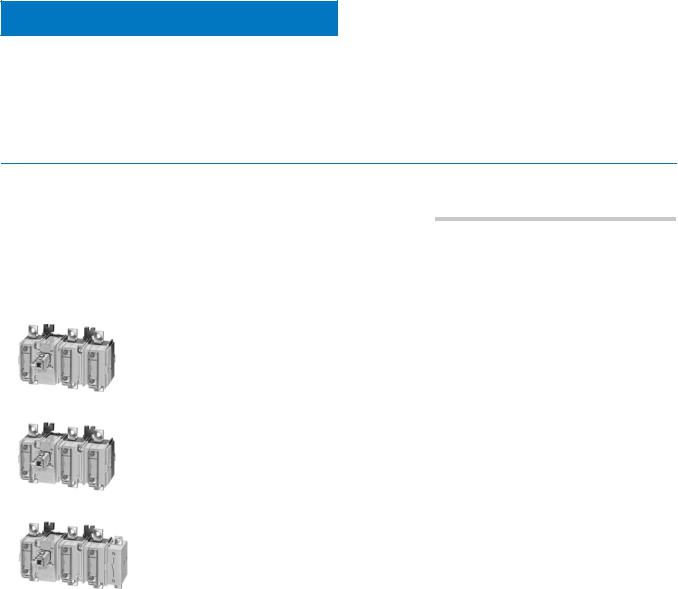
SENTRIC Switch Disconnectors
SENTRIC K Switch Disconnectors from 63 A to 1000 A
Base mounting
■ Area of application |
|
SENTRIC KA switch disconnectors are implemented as main |
Main control switches and EMERGENCY-STOP switches are |
control switches and EMERGENCY-STOP switches for normal |
hand-operated switch disconnectors acc. to IEC 60947-3 and |
switching duty and isolation of main circuits and auxiliary cir- |
VDE 0660 Part 107 (EN 60947-3) and comply with the isolation |
cuits. Another area of application is the switching of three-phase |
conditions and the requirements of machine guideline |
induction motors and other loads for maintenance and repair |
EN 60204-1. |
work. |
|
■ Selection and ordering data
All switch disconnectors to the IP00 degree of protection
Conductor connecting screws are generally included in the scope of supply.
|
|
|
Rated |
DT |
Complete |
PS* |
Weight |
DT |
Basic switch |
PS* |
Weight |
DT |
8UC6 EMER- |
PS* |
Weight |
|
|
|
uninter- |
|
version with |
|
per PU |
|
version |
|
per PU |
|
GENCY-STOP |
|
per PU |
|
|
|
rupted |
|
8UC6 door-cou- |
|
ap- |
|
without handle |
|
ap- |
|
door-coupling |
|
ap- |
|
|
|
current |
|
pling rotary oper- |
|
prox. |
|
|
|
prox. |
|
rotary operating |
|
prox. |
|
|
|
Iu |
|
ating mechanism |
|
|
|
|
|
|
|
mechanism (red |
|
|
|
|
|
|
|
(black handle) |
|
|
|
|
|
|
|
handle, yellow |
|
|
|
|
|
|
|
|
|
|
|
|
|
|
|
indicator plate) |
|
|
|
|
|
A |
|
Order No. |
|
|
|
Order No. |
|
kg |
|
Order No. |
|
kg |
7 |
|
|
3-pole for motor loads |
|
|
|
|
|
|
|
|
|
|
||
|
|
63 |
B |
3KA50 30–1EE01 |
1 unit |
1.440 |
} |
3KA50 30–1AE01 |
1 unit |
0.946 |
} |
8UC61 21–3BB10 |
1 unit |
0.353 |
|
|
|
|
80 |
B |
3KA51 30–1EE01 |
1 unit |
1.400 |
} |
3KA51 30–1AE01 |
1 unit |
0.918 |
} |
8UC61 21–3BB10 |
1 unit |
0.353 |
|
|
|
125 |
B |
3KA52 30–1EE01 |
1 unit |
2.380 |
} |
3KA52 30–1AE01 |
1 unit |
1.880 |
} |
8UC62 22–3BB20 |
1 unit |
0.426 |
|
|
|
160 |
B |
3KA53 30–1EE01 |
1 unit |
2.420 |
} |
3KA53 30–1AE01 |
1 unit |
2.020 |
} |
8UC62 22–3BB20 |
1 unit |
0.426 |
|
|
|
250 |
B |
|
1 unit |
5.470 |
|
|
1 unit |
4.510 |
|
|
1 unit |
0.999 |
|
|
|
3KA55 30–1EE01 |
} |
3KA55 30–1AE01 |
} |
8UC63 23–3BB30 |
||||||||
|
|
|
400 |
B |
3KA57 30–1EE01 |
1 unit |
5.550 |
} |
3KA57 30–1AE01 |
1 unit |
4.630 |
} |
8UC63 23–3BB30 |
1 unit |
0.999 |
|
|
3KA53 30–1AE01 |
630 |
B |
3KA58 30–1EE01 |
1 unit |
6.120 |
} |
3KA58 30–1AE01 |
1 unit |
5.150 |
} |
8UC63 23–3BB30 |
1 unit |
0.999 |
|
|
|
|
|
|
|
|
|
|
|
|
|
|
|
|
|
|
|
3-pole for power distribution |
|
|
|
|
|
|
|
|
|
|||
|
|
|
63 |
B |
3KA50 30–1EE01 |
1 unit |
1.440 |
} |
3KA50 30–1AE01 |
1 unit |
0.946 |
} |
8UC61 21–3BB10 |
1 unit |
0.353 |
|
|
|
80 |
B |
3KA51 30–1EE01 |
1 unit |
1.400 |
} |
3KA51 30–1AE01 |
1 unit |
0.918 |
} |
8UC61 21–3BB10 |
1 unit |
0.353 |
|
|
|
125 |
B |
|
1 unit |
2.380 |
} |
|
1 unit |
1.880 |
} |
|
1 unit |
0.426 |
|
|
|
3KA52 30–1EE01 |
3KA52 30–1AE01 |
8UC62 22–3BB20 |
||||||||||
|
|
|
160 |
B |
3KA53 30–1EE01 |
1 unit |
2.420 |
} |
3KA53 30–1AE01 |
1 unit |
2.020 |
} |
8UC62 22–3BB20 |
1 unit |
0.426 |
|
|
|
250 |
B |
|
1 unit |
5.470 |
|
|
1 unit |
4.510 |
|
|
0.999 |
|
|
|
|
3KA55 30–1EE01 |
} |
3KA55 30–1AE01 |
} |
8UC63 23–3BB30 |
1 unit |
|||||||
|
|
|
400 |
B |
3KA57 30–1EE01 |
1 unit |
5.550 |
} |
3KA57 30–1AE01 |
1 unit |
4.630 |
} |
8UC63 23–3BB30 |
1 unit |
0.999 |
|
|
3KA53 30–1AE01 |
630 |
B |
3KA58 30–1EE01 |
1 unit |
6.120 |
} |
3KA58 30–1AE01 |
1 unit |
5.150 |
} |
8UC63 23–3BB30 |
1 unit |
0.999 |
|
|
|
|
|
|
|
|
|
|
|
|
|
|
|
|
|
|
|
4-pole1) for |
power distribution |
|
|
|
|
|
|
|
|
|
||
|
|
|
63 |
B |
3KA50 40–1EE01 |
1 unit |
2.490 |
B |
3KA50 40–1AE01 |
1 unit |
2.100 |
} |
8UC62 22–3BB20 |
1 unit |
0.426 |
|
|
|
80 |
B |
3KA51 40–1EE01 |
1 unit |
2.540 |
B |
3KA51 40–1AE01 |
1 unit |
2.110 |
} |
8UC62 22–3BB20 |
1 unit |
0.426 |
|
|
|
125 |
B |
3KA52 40–1EE01 |
1 unit |
2.490 |
B |
3KA52 40–1AE01 |
1 unit |
2.090 |
} |
8UC62 22–3BB20 |
1 unit |
0.426 |
|
|
|
160 |
B |
3KA53 40–1EE01 |
1 unit |
2.450 |
B |
3KA53 40–1AE01 |
1 unit |
2.240 |
} |
8UC62 22–3BB20 |
1 unit |
0.426 |
|
|
|
250 |
B |
|
1 unit |
6.030 |
C |
|
1 unit |
5.040 |
|
|
0.999 |
|
|
|
|
3KA55 40–1EE01 |
3KA55 40–1AE01 |
} |
8UC63 23–3BB30 |
1 unit |
||||||||
|
|
|
400 |
B |
3KA57 40–1EE01 |
1 unit |
5.150 |
B |
3KA57 40–1AE01 |
1 unit |
5.190 |
} |
8UC63 23–3BB30 |
1 unit |
0.999 |
|
|
3KA53 40–1AE01 |
630 |
C |
3KA58 40–1EE01 |
1 unit |
6.590 |
B |
3KA58 40–1AE01 |
1 unit |
5.740 |
} |
8UC63 23–3BB30 |
1 unit |
0.999 |
|
|
|
|
|
|
|
|
|
|
|
|
|
|
|
|
|
|
|
|
|
|
|
|
|
|
|
|
|
|
|
|
1)The nominal values are reduced in the case of strong harmonics due to frequency converter operation.
7/14 |
Siemens LV 10 · 2004 |
* This quantity or a multiple thereof can be ordered. |
|
|
|
|
|
|
|
SENTRIC Switch Disconnectors |
|||
|
|
SENTRIC K Switch Disconnectors from 63 A to 1000 A |
|||||
|
|
|
|
|
Molded-plastic enclosures |
||
|
|
|
|
|
|
|
|
■ Benefits |
|
■ Area of application |
|||||
|
• Lockable with 3 padlocks |
|
|
|
Our master and EMERCENCY-STOP switches provide absolute |
||
|
• Generous terminal compartment |
|
|
|
safety, even during maintenance and repair work. All-round |
||
|
• IP65 degree of protection |
|
|
|
safety for people and machines. |
||
|
|
|
|
|
|
|
|
|
• Maintenance-free |
|
|
|
With their high degree of protection of IP65, they can even with- |
||
|
• Easy to install. |
|
|
|
stand dust and water spray, providing unparalleled safety in the |
||
|
|
|
|
building and industrial installations as well as the food and |
|||
|
|
|
|
|
|||
|
|
|
|
|
chemical industry. Even with their enclosures open, they con- |
||
|
|
|
|
|
form to protection class 2. IP20 is the minimum degree of protec- |
||
|
|
|
|
|
tion. |
||
|
|
|
|
|
|
|
|
■ Functions |
|
|
|
|
|
|
|
The concept and mechanical construction of these switches are designed for reliable function even under the harshest conditions. In emergencies, every second counts, and our switches allow immediate isolation.
Our enclosed master and EMERGENCY-STOP switches can be locked with up to three padlocks and are available in two ergonomically designed versions: from 16 A to 1000 A.
■ Selection and ordering data
|
|
|
|
|
|
|
|
|
|
|
|
Main |
Auxiliary |
P/AC-23 A |
at |
Iu |
Conductor cross-section |
DT |
Order No. |
PS* |
Weight |
|
|
contacts |
contacts |
at |
|
main conductor/PEN |
|
|
|
per PU |
|
7 |
|
|
|
380 ... 400 V |
660/690 V |
|
|
|
|
|
approx. |
|
|
|
|
|
|
|
|
|
|
|
|
|
|
|
|
kW |
kW |
A |
mm2 |
|
|
|
kg |
|
|
|
|
|
|
|
|
Main control switch complete with rotary operating mechanism, black1)
3 |
– |
65 |
110 |
125 |
35/352) |
C |
8HP27 07 |
1 unit |
5.240 |
||
|
|
|
80 |
150 |
160 |
120/702) |
C |
8HP27 11 |
1 unit |
8.030 |
|
|
|
|
132 |
220 |
250 |
150/702) |
C |
8HP27 12 |
1 unit |
12.200 |
|
|
|
|
200 |
375 |
400 |
2 |
× 150 or 1 × 240/120 |
C |
8HP27 17 |
1 unit |
12.300 |
|
|
|
350 |
375 |
630 |
2 |
× 240/120 |
C |
8HP27 18 |
1 unit |
13.000 |
8HP27.. |
|
|
315 |
315 |
8003) |
2 |
× 240/240 |
C |
8HP27 38 |
1 unit |
14.200 |
EMERGENCY-STOP switch complete with rotary operating mechanism, red/yellow1) |
|
|
|||||||||
|
|
|
|||||||||
3 |
– |
65 |
110 |
125 |
35/352) |
C |
8HP27 47 |
1 unit |
5.210 |
||
|
|
|
80 |
150 |
160 |
120/702) |
C |
8HP27 48 |
1 unit |
7.990 |
|
|
|
|
132 |
220 |
250 |
150/702) |
C |
8HP27 61 |
1 unit |
12.300 |
|
|
|
|
200 |
375 |
400 |
2 |
× 150 or 1 × 240/120 |
C |
8HP27 62 |
1 unit |
12.300 |
|
|
|
350 |
375 |
630 |
2 |
× 240/120 |
C |
|
1 unit |
12.800 |
|
|
|
8HP27 63 |
||||||||
|
|
|
315 |
315 |
8003) |
2 |
× 240/240 |
C |
8HP27 58 |
1 unit |
14.300 |
1)With PE/ground/ N terminal.
2)For a 5th conductor another terminal of this type can be installed.
3)For ambient temperatures up to 35 °C.
* This quantity or a multiple thereof can be ordered. |
Siemens LV 10 · 2004 |
7/15 |
|
|
|
 Loading...