siemens 840Dsl User Manual

SINUMERIK
SINUMERIK 840D sl / 828D Ctrl-Energy
System Manual
Valid for
Control system SINUMERIK 840D sl / 840DE sl SINUMERIK 828D
Software
CNC software version 4.5
02/2012
___________________
Preface
Introduction |
1 |
|
|
|
|
Ctrl-E Analysis |
2 |
|
|
|
|
Ctrl-E Profiles |
3 |
|
Reactive power |
|
|
4 |
||
compensation |
||
|
|
|
Flux reduction |
5 |
|
|
|
|
User know-how |
6 |
|
|
|
|
Appendix |
A |
|
|
|
6FC5397-0EP40-3BA0

Legal information
Warning notice system
This manual contains notices you have to observe in order to ensure your personal safety, as well as to prevent damage to property. The notices referring to your personal safety are highlighted in the manual by a safety alert symbol, notices referring only to property damage have no safety alert symbol. These notices shown below are graded according to the degree of danger.
 DANGER
indicates that death or severe personal injury will result if proper precautions are not taken.
 WARNING
indicates that death or severe personal injury may result if proper precautions are not taken.
 CAUTION
with a safety alert symbol, indicates that minor personal injury can result if proper precautions are not taken.
CAUTION
without a safety alert symbol, indicates that property damage can result if proper precautions are not taken.
NOTICE
indicates that an unintended result or situation can occur if the relevant information is not taken into account.
If more than one degree of danger is present, the warning notice representing the highest degree of danger will be used. A notice warning of injury to persons with a safety alert symbol may also include a warning relating to property damage.
Qualified Personnel
The product/system described in this documentation may be operated only by personnel qualified for the specific task in accordance with the relevant documentation, in particular its warning notices and safety instructions. Qualified personnel are those who, based on their training and experience, are capable of identifying risks and avoiding potential hazards when working with these products/systems.
Proper use of Siemens products
Note the following:
 WARNING
Siemens products may only be used for the applications described in the catalog and in the relevant technical documentation. If products and components from other manufacturers are used, these must be recommended or approved by Siemens. Proper transport, storage, installation, assembly, commissioning, operation and maintenance are required to ensure that the products operate safely and without any problems. The permissible ambient conditions must be complied with. The information in the relevant documentation must be observed.
Trademarks
All names identified by ® are registered trademarks of Siemens AG. The remaining trademarks in this publication may be trademarks whose use by third parties for their own purposes could violate the rights of the owner.
Disclaimer of Liability
We have reviewed the contents of this publication to ensure consistency with the hardware and software described. Since variance cannot be precluded entirely, we cannot guarantee full consistency. However, the information in this publication is reviewed regularly and any necessary corrections are included in subsequent editions.
Siemens AG |
Order number: 6FC5397-0EP40-3BA0 |
Copyright © Siemens AG 2012. |
Industry Sector |
04/2012 Technical data subject to change |
All rights reserved |
Postfach 48 48 |
|
|
90026 NÜRNBERG |
|
|
GERMANY |
|
|
Preface
SINUMERIK documentation
SINUMERIK documentation
The SINUMERIK documentation is organized in the following categories:
●General documentation
●User documentation
●Manufacturer/service documentation
Additional information
You can find information on the following topics at www.siemens.com/motioncontrol/docu:
●Ordering documentation/overview of documentation
●Additional links to download documents
●Using documentation online (find and search in manuals/information)
Please send any questions about the technical documentation (e.g. suggestions for improvement, corrections) to the following address:
docu.motioncontrol@siemens.com
My Documentation Manager (MDM)
Under the following link you will find information to individually compile OEM-specific machine documentation based on the Siemens content:
www.siemens.com/mdm
Training
For information about the range of training courses, refer under:
●www.siemens.com/sitrain
SITRAIN - Siemens training for products, systems and solutions in automation technology
●www.siemens.com/sinutrain
SinuTrain - training software for SINUMERIK
FAQs
You can find Frequently Asked Questions in the Service&Support pages under Product Support. http://support.automation.siemens.com
Ctrl-Energy |
|
System Manual, 02/2012, 6FC5397-0EP40-3BA0 |
3 |

Preface
SINUMERIK
You can find information on SINUMERIK under the following link: www.siemens.com/sinumerik
Hotline and Internet address
Technical Support
You will find telephone numbers for other countries for technical support in the Internet under http://www.siemens.com/automation/service&support
EC Declaration of Conformity
The EC Declaration of Conformity for the EMC Directive can be found on the Internet at: http://support.automation.siemens.com
Here, enter the number 15257461 as the search term or contact your local Siemens office.
|
Ctrl-Energy |
4 |
System Manual, 02/2012, 6FC5397-0EP40-3BA0 |
Table of contents
|
Preface...................................................................................................................................................... |
|
3 |
1 |
Introduction................................................................................................................................................ |
7 |
|
2 |
Ctrl-E Analysis........................................................................................................................................... |
9 |
|
|
2.1 |
SENTRON PAC3200/4200.......................................................................................................... |
10 |
|
2.1.1 |
Hardware...................................................................................................................................... |
10 |
|
2.1.2 |
Commissioning the Power Monitoring Device............................................................................. |
12 |
|
2.1.3 |
Commissioning the PAC PROFIBUS expansion module (840D sl) ............................................ |
13 |
|
2.1.4 |
Commissioning the expansion module PAC PROFINET (828D)................................................ |
13 |
|
2.2 |
Commissioning the PLC for SENTRON PAC.............................................................................. |
15 |
|
2.2.1 |
SINUMERIK 840D sl.................................................................................................................... |
15 |
|
2.2.1.1 |
Commissioning the PLC with PROFIBUS ................................................................................... |
15 |
|
2.2.1.2 |
Commissioning the PLC with PROFINET.................................................................................... |
19 |
|
2.2.2 |
SINUMERIK 828D ....................................................................................................................... |
22 |
|
2.3 |
Commissioning the PLC for Ctrl-E Analysis ................................................................................ |
23 |
|
2.3.1 |
Configuring the energy consumption display for SINUMERIK 840D sl....................................... |
23 |
|
2.3.1.1 |
PLC user program for SINUMERIK 840D sl programming.......................................................... |
25 |
|
2.3.2 |
Configuring the display of energy consumption for SINUMERIK 828D....................................... |
28 |
|
2.3.2.1 |
Programming the PLC user program for SINUMERIK 828D....................................................... |
30 |
|
2.4 |
Commissioning the HMI for Ctrl-E Analysis................................................................................. |
34 |
|
2.5 |
Long time measurement.............................................................................................................. |
34 |
3 |
Ctrl-E Profiles .......................................................................................................................................... |
35 |
|
|
3.1 |
Commissioning the PLC for Ctrl-E Profiles.................................................................................. |
36 |
|
3.1.1 |
Overview...................................................................................................................................... |
36 |
|
3.1.2 |
Automatic state machine PLC functions...................................................................................... |
37 |
|
3.1.3 |
Checking the energy-saving states.............................................................................................. |
39 |
|
3.1.4 |
PLC user program........................................................................................................................ |
41 |
|
3.1.5 |
Interface signals 840D sl.............................................................................................................. |
42 |
|
3.1.5.1 |
Signals for controlling energy-saving profiles.............................................................................. |
42 |
|
3.1.5.2 |
Signals for parameterization........................................................................................................ |
43 |
|
3.1.6 |
Interface signals 828D................................................................................................................. |
45 |
|
3.1.6.1 |
Signals for controlling energy-saving profiles.............................................................................. |
45 |
|
3.1.6.2 |
Signals for parameterization........................................................................................................ |
46 |
|
3.2 |
Creating and editing energy-saving profiles ................................................................................ |
47 |
4 |
Reactive power compensation................................................................................................................. |
51 |
|
5 |
Flux reduction.......................................................................................................................................... |
53 |
|
6 |
User know-how........................................................................................................................................ |
55 |
|
|
6.1 |
Commissioning user screen forms .............................................................................................. |
55 |
A |
Appendix.................................................................................................................................................. |
|
57 |
Ctrl-Energy |
|
|
|
System Manual, 02/2012, 6FC5397-0EP40-3BA0 |
5 |
||

Table of contents
A.1 |
Overview..................................................................................................................................... |
57 |
Index |
........................................................................................................................................................ |
59 |
|
Ctrl-Energy |
6 |
System Manual, 02/2012, 6FC5397-0EP40-3BA0 |
Introduction |
1 |
The topics of energy efficiency and energy saving are also playing an increasingly important role in the machine tool environment.
With SINUMERIK Ctrl-Energy, Siemens is offering an extensive range of components, functions, software tools and services to increase the efficiency of machine tools.
Ctrl-Energy
You will find an overview of the complete range of functions under the following link: www.siemens.com/sinumerik/ctrl-energy
Acquisition, evaluation, and control of energy consumption
The functions Ctrl-E Analysis to acquire and evaluate the energy consumption of the machine and Ctrl-E Profiles, to control energy-saving states of the machine are available in SINUMERIK Operate. Additional energy-saving functions or user know-how on this topic can be added in this area of SINUMERIK Operate.
Ctrl-Energy |
|
System Manual, 02/2012, 6FC5397-0EP40-3BA0 |
7 |

Introduction
|
Ctrl-Energy |
8 |
System Manual, 02/2012, 6FC5397-0EP40-3BA0 |
Ctrl-E Analysis |
2 |
In order to sensitize users to the topic of energy efficiency, the power and energy data of the machine are first acquired.
Acquiring and evaluating energy consumption
A control system with SINUMERIK Operate without a connected measuring instrument determines the power directly from the drives and displays this.
Additional consumption-relevant data can be retrieved and displayed at the control using the additional SENTRON PAC Power Monitoring Device.
Depending on where the SENTRON PAC measuring transducer is installed, you have the possibility of either measuring the power of the whole machine or only a specific load.
With an integrated measuring function, the energy consumption during a measuring period can be acquired for all drives together with an additional measuring location – and the electrical power drawn for a selected load can be recorded with respect to time.
Maximum measuring time
The maximum measuring time for energy between start and stop as well as for an NC part program is, as a result of the trace recording, 922 seconds (00:15:22).
Ctrl-Energy |
|
System Manual, 02/2012, 6FC5397-0EP40-3BA0 |
9 |

Ctrl-E Analysis
2.1 SENTRON PAC3200/4200
2.1SENTRON PAC3200/4200
2.1.1Hardware
Hardware components
You require the following hardware in order to be able to use all of the "Ctrl-Energy" functions:
●SENTRON PAC3200 (Firmware ≥ V2.2.0) http://support.automation.siemens.com/WW/view/de/25240652/130000
●SENTRON PAC4200 (Firmware ≥ V1.4.0) http://support.automation.siemens.com/WW/view/de/31675630/130000
●SENTRON PAC - accessories
http://www.automation.siemens.com/btlv-static/Lowvoltage_LV10- 1_complete_German_2011.pdf
–Power Monitoring Device (page 11/27 ff)
–Current transformer (Page 11/39)
●The expansion modules must be temporarily removed in order to upgrade the firmware using powerconfig.
●Protection/fusing of the supply and measuring voltages according to Configuration Manual
●Expansion module PAC PROFINET; order number 7KM 9300-0AE00-0AA0
●Expansion module PAC PROFIBUS; order number 7KM 9300-0AB00-0AA0
|
Ctrl-Energy |
10 |
System Manual, 02/2012, 6FC5397-0EP40-3BA0 |

Ctrl-E Analysis
2.1 SENTRON PAC3200/4200
●PC software powerconfig (≥ V2.2) http://support.automation.siemens.com/WW/view/de/50246395
●Current transformer depending on
–the connection type at the SENTRON PAC
–Accuracy requirements
–Currents
 DANGER
Open current transformer circuits result in electric shock and arcing
If not observed, will cause death, serious injury or considerable property damage.
Only measure the current using external current transformers. DO NOT protect the circuits using a fuse. Do not open the secondary circuit of the current transformer under load. Short circuit the secondary current terminals of the current transformer before removing this device. The safety information for the current transformers used must be carefully followed.
Selection example
Catalog, Siemens LV 1/Accessories and spare parts:
For a three-phase measurement according to connection type 3P4W (four conductors, unbalanced load, without voltage transformers, with three current transformers), accuracy class 1, primary rated current 100 A, rated secondary current 1A, three window-type current transformers are recommended (4CN51 17-0CC20).
Note
When measuring the complete machine, it is recommended that the current is sensed directly after the main switch. For the voltage tap, please observe the usual protection/fusing.
References
Information on the installation, configuration and operation of the Power Monitoring Device and the expansion module can be found in the following references:
●SENTRON PAC3200 Power Monitoring Device manual (Document order number A5E01168664A-05)
●SENTRON PAC4200 Power Monitoring Device system manual (Document order number A5E02316180A-03)
●Manual, expansion module PAC PROFIBUS DP, SWITCHED ETHERNET PROFINET (document order number A5E01168846A-06)
Ctrl-Energy |
|
System Manual, 02/2012, 6FC5397-0EP40-3BA0 |
11 |

Ctrl-E Analysis
2.1 SENTRON PAC3200/4200
2.1.2Commissioning the Power Monitoring Device
A detailed description of commissioning of the SENTRON PAC Power Monitoring Device is provided in the corresponding manuals.
Preconditions
●The device has been installed.
●The optional expansion modules have been installed.
●The device has been connected in accordance with the possible connection methods.
●The battery has been inserted into the battery compartment (only for the SENTRON PAC4200).
General procedure when commissioning the device
●Connected the supply voltage
●Parameterizing SENTRON PAC
●Connect the measuring voltage
●Connect the current to be measured
●Check the displayed measured values
●Check the polarity and phase assignment of the measuring transducer
Parameterizing SENTRON PAC
You have the option of parameterizing the measuring device in the following ways:
●Using the input keys and display of the SENTRON PAC
●Using a PC connected to the SENTRON PAC, which has the software this has been supplied (powerconfig).
After booting select the language and the measuring device is then ready for operation.
|
Ctrl-Energy |
12 |
System Manual, 02/2012, 6FC5397-0EP40-3BA0 |

Ctrl-E Analysis
2.1 SENTRON PAC3200/4200
2.1.3Commissioning the PAC PROFIBUS expansion module (840D sl)
To communicate via Profibus, the SENTRON PROFIBUS module in combination with Sentron PAC3200/4200 must be parameterized differently.
1.Select SENTRON PAC "Settings" > "PROFIBUS modules". - OR -
For SENTRON PAC4200, select "Settings" > "Expansion modules" > "MOD1" > "PROFIBUS MODULE".
2.Press "Enter".
You obtain the following information in the subsequent window:
–Order number
–Serial number of the SENTRON PROFIBUS module
–Firmware version of the SENTRON PROFIBUS module
–PROFIBUS ADDR.:
The DP address of module is displayed here.
3.Press "Enter".
This means that you have the option of entering the same PROFIBUS address as in the automation system.
2.1.4Commissioning the expansion module PAC PROFINET (828D)
To communicate via PROFINET, the SENTRON SWITCHED ETHERNET PROFINET module in combination with Sentron PAC3200/4200 must be parameterized differently.
1.Select SENTRON PAC "Settings" > "SWITCHED ETHERNET". - OR -
Select SENTRON PAC "Settings" > "Expansion modules" > "MOD1" > "SWITCHED
ETHERNET".
2.Press "ENTER".
You obtain the following information in the subsequent window:
–Order number
–Serial number of the SENTRON SWITCHED ETHERNET PROFINET module
–Firmware version of the SENTRON SWITCHED ETHERNET PROFINET module
–The first character of the NameOfStation of the SENTRON SWITCHED ETHERNET PROFINET module that can be a maximum of 26 characters
–IP-ADDR.:
The IP address of the module is displayed here.
3.Using the menu item "- ->", open the next window and obtain among other things the information about the SUBNET address of the module.
Ctrl-Energy |
|
System Manual, 02/2012, 6FC5397-0EP40-3BA0 |
13 |

Ctrl-E Analysis
2.1 SENTRON PAC3200/4200
Specifying/changing the device name
The device name can only be entered (it must be specified) using the powerconfig software in the submenu "Expansion slot1".
●Sentron PAC3200: pac3200-pn22
●Sentron PAC4200: pac4200-pn21
The next time that the 828D boots, the 828D IO controller assigns the correct IP address to the expansion module according to the device name:
●pac4200-pn21 --> 192.168.214.21
●pac3200-pn22 --> 192.168.214.22
|
Ctrl-Energy |
14 |
System Manual, 02/2012, 6FC5397-0EP40-3BA0 |

Ctrl-E Analysis
2.2 Commissioning the PLC for SENTRON PAC
2.2Commissioning the PLC for SENTRON PAC
2.2.1SINUMERIK 840D sl
2.2.1.1Commissioning the PLC with PROFIBUS
PROFIBUS is commissioned with the PLC Toolbox 4.5 or higher.
Preconditions
●Configure the hardware, save and compile the project
●Generating the system data for the PLC
●Install the Toolbox software, which also contains the libraries for the PLC basic program of an NCU 7x0.3.
Note
Starting from STEP7 V5.5 SP1 and higher, SENTRON with PROFIBUS is listed as standard in the HW catalog.
Procedure
You are on the main screen of the SIMATIC Manager.
1.Select the "File" > "Open" menu and then click on the "Libraries" tab.
2.Select the library for the PLC basic program "bp7x0_45" and confirm the dialog with "OK".
3.You have inserted the library and selected the PLC program under "PLC-First-Startup 840D sl" > "SINUMERIK" > "PLC317F-3 PN/DP " > "S7 Program".
Ctrl-Energy |
|
System Manual, 02/2012, 6FC5397-0EP40-3BA0 |
15 |

Ctrl-E Analysis
2.2Commissioning the PLC for SENTRON PAC
4.Copy the sources, modules and symbols to the PLC program
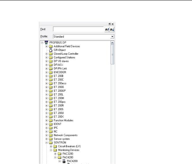
Figure 2-1 Hardware catalog after incorporating the GSD file
|
Ctrl-Energy |
16 |
System Manual, 02/2012, 6FC5397-0EP40-3BA0 |

Ctrl-E Analysis
2.2 Commissioning the PLC for SENTRON PAC
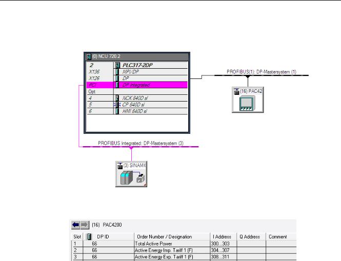
5. In HW Config, drag the selected module to the Profibus DP master system.
6.In the hardware catalog, open the required module and assign the subslots as shown in the diagram.
Ctrl-Energy |
|
System Manual, 02/2012, 6FC5397-0EP40-3BA0 |
17 |

Ctrl-E Analysis
2.2 Commissioning the PLC for SENTRON PAC
PROFIBUS interface
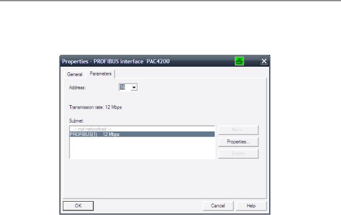
PROFIBUS must be configured with a data transfer rate of 12 Mbit/s.
Setting the PROFIBUS address
Set the PROFIBUS address of the expansion module either directly at the SENTRON PAC or enter using the powerconfig software.
References
Additional information about commissioning the PLC can be found in the following references:
CNC Commissioning Manual: NCK, PLC, drive / SINUMERIK 840D sl
|
Ctrl-Energy |
18 |
System Manual, 02/2012, 6FC5397-0EP40-3BA0 |
 Loading...