


 Loading...
SINUMERIK
SINUMERIK 840D sl / 828D Measuring cycles
Programming Manual
Valid for:
SINUMERIK 840D sl / 840DE sl / 828D controls
Software |
Version 4.5 SP2 |
CNC software, |
|
SINUMERIK Operate for PCU/PC |
Version 4.5 SP2 |
03/2013
___________________
Preface
Description |
1 |
|
|
|
|
Measuring variants |
2 |
|
|
|
|
Parameter lists |
3 |
|
Changes from cycle version |
|
|
A |
||
SW 4.4 and higher |
||
|
|
|
Appendix |
B |
|
|
|
6FC5398-4BP40-3BA1

Legal information
Warning notice system
This manual contains notices you have to observe in order to ensure your personal safety, as well as to prevent damage to property. The notices referring to your personal safety are highlighted in the manual by a safety alert symbol, notices referring only to property damage have no safety alert symbol. These notices shown below are graded according to the degree of danger.
 DANGER
indicates that death or severe personal injury will result if proper precautions are not taken.
 WARNING
indicates that death or severe personal injury may result if proper precautions are not taken.
 CAUTION
indicates that minor personal injury can result if proper precautions are not taken.
NOTICE
indicates that property damage can result if proper precautions are not taken.
If more than one degree of danger is present, the warning notice representing the highest degree of danger will be used. A notice warning of injury to persons with a safety alert symbol may also include a warning relating to property damage.
Qualified Personnel
The product/system described in this documentation may be operated only by personnel qualified for the specific task in accordance with the relevant documentation, in particular its warning notices and safety instructions. Qualified personnel are those who, based on their training and experience, are capable of identifying risks and avoiding potential hazards when working with these products/systems.
Proper use of Siemens products
Note the following:
 WARNING
Siemens products may only be used for the applications described in the catalog and in the relevant technical documentation. If products and components from other manufacturers are used, these must be recommended or approved by Siemens. Proper transport, storage, installation, assembly, commissioning, operation and maintenance are required to ensure that the products operate safely and without any problems. The permissible ambient conditions must be complied with. The information in the relevant documentation must be observed.
Trademarks
All names identified by ® are registered trademarks of Siemens AG. The remaining trademarks in this publication may be trademarks whose use by third parties for their own purposes could violate the rights of the owner.
Disclaimer of Liability
We have reviewed the contents of this publication to ensure consistency with the hardware and software described. Since variance cannot be precluded entirely, we cannot guarantee full consistency. However, the information in this publication is reviewed regularly and any necessary corrections are included in subsequent editions.
Siemens AG |
Order number: 6FC5398-4BP40-3BA1 |
Copyright © Siemens AG 2006 - 2013. |
Industry Sector |
04/2013 Technical data subject to change |
All rights reserved |
Postfach 48 48 |
|
|
90026 NÜRNBERG |
|
|
GERMANY |
|
|
Preface
SINUMERIK documentation
The SINUMERIK documentation is organized in the following categories:
●General documentation
●User documentation
●Manufacturer/service documentation
Additional information
You can find information on the following topics at www.siemens.com/motioncontrol/docu:
●Ordering documentation/overview of documentation
●Additional links to download documents
●Using documentation online (find and search in manuals/information)
Please send any questions about the technical documentation (e.g. suggestions for improvement, corrections) to the following address:
docu.motioncontrol@siemens.com
My Documentation Manager (MDM)
Under the following link you will find information to individually compile OEM-specific machine documentation based on the Siemens content:
www.siemens.com/mdm
Training
For information about the range of training courses, refer under:
●www.siemens.com/sitrain
SITRAIN - Siemens training for products, systems and solutions in automation technology
●www.siemens.com/sinutrain
SinuTrain - training software for SINUMERIK
FAQs
You can find Frequently Asked Questions in the Service&Support pages under Product Support. http://support.automation.siemens.com
Measuring cycles |
|
Programming Manual, 03/2013, 6FC5398-4BP40-3BA1 |
3 |

Preface
SINUMERIK
You can find information on SINUMERIK under the following link: www.siemens.com/sinumerik
Target group
This programming manual is intended for machine tool programmers for the SINUMERIK Operate software.
Benefits
With the programming manual, the target group can develop, write, test, and debug programs and software user interfaces.
Standard scope
This documentation only describes the functionality of the standard version. Additions or revisions made by the machine manufacturer are documented by the machine manufacturer.
Other functions not described in this documentation might be executable in the control. This does not, however, represent an obligation to supply such functions with a new control or when servicing.
For the sake of simplicity, this documentation does not contain all detailed information about all types of the product and cannot cover every conceivable case of installation, operation, or maintenance.
Technical Support
You will find telephone numbers for other countries for technical support in the Internet under http://www.siemens.com/automation/service&support
|
Measuring cycles |
4 |
Programming Manual, 03/2013, 6FC5398-4BP40-3BA1 |
Table of contents
|
Preface |
...................................................................................................................................................... |
3 |
1 |
Description................................................................................................................................................. |
9 |
|
|
1.1 |
Basics ............................................................................................................................................. |
9 |
|
1.2 ................................................................................................................... |
General prerequisites |
11 |
|
1.3 .................................................. |
Behavior on block search, dry run, program testing, simulation |
12 |
|
1.4 ........................................................................ |
Reference points on the machine and workpiece |
13 |
|
1.5 ............................................................................................... |
Definition of the planes, tool types |
15 |
|
1.6 .............................................................................................................. |
Probes that can be used |
18 |
|
1.7 ....................................................................................... |
Probe, calibration body, calibration tool |
22 |
|
1.7.1 ................................................. |
Measuring workpieces on milling machines, machining centers |
22 |
|
1.7.2 ........................................................... |
Measuring tools on milling machines, machining centers |
23 |
|
1.7.3 ........................................................................... |
Measuring workpieces at the turning machines |
25 |
|
1.7.4 ............................................................................................................. |
Measuring tools at lathes |
28 |
|
1.8 ................................................................................................................. |
Measurement principle |
30 |
|
1.9 .................................................... |
Measuring strategy for measuring workpieces with tool offset |
35 |
|
1.10 ...................................................... |
Parameters for checking the measurement result and offset |
38 |
|
1.11 ............................................... |
Effect of empirical value, mean value, and tolerance parameters |
43 |
|
1.12 ................................................................................................... |
Measuring cycle help programs |
44 |
|
1.12.1 ..................................................... |
CYCLE116: Calculation of center point and radius of a circle |
44 |
|
1.12.2 .............................. |
CUST _ MEACYC: User program before/after measurements are performed |
46 |
|
1.13 ............................................................................................................... |
Miscellaneous functions |
47 |
|
1.13.1 ............................................................................ |
Measuring cycle support in the program editor |
47 |
|
1.13.2 ............................................................................................................. |
Measuring result screens |
47 |
2 |
Measuring ..................................................................................................................................variants |
51 |
|
|
2.1 .................................................................................................................. |
General requirements |
51 |
|
2.1.1 ............................................................................................... |
Overview of the measuring cycles |
51 |
|
2.1.2 .......................................................... |
Selection of the measuring variants via softkeys (turning) |
53 |
|
2.1.3 ........................................................... |
Selection of the measuring variants via softkeys (milling) |
55 |
|
2.1.4 ........................................................................................................................ |
Result parameters |
57 |
|
2.2 ....................................................................................................... |
Measure workpiece (turning) |
58 |
|
2.2.1 ..................................................................................................................... |
General information |
58 |
|
2.2.2 .......................................................................................... |
Calibrate probe - length (CYCLE973) |
59 |
|
2.2.3 ........................................................................ |
Calibrate probe - radius on surface (CYCLE973) |
62 |
|
2.2.4 ...................................................................... |
Calibrate probe - calibrate in groove (CYCLE973) |
65 |
|
2.2.5 ......................................................................... |
Turning measurement - front edge (CYCLE974) |
69 |
|
2.2.6 ............................................ |
Turning measurement - inside diameter (CYCLE974, CYCLE994) |
73 |
|
2.2.7 .......................................... |
Turning measurement - outside diameter (CYCLE974, CYCLE994) |
78 |
|
2.2.8 ............................................................................................................... |
Extended measurement |
83 |
Measuring cycles |
|
|
|
Programming Manual, 03/2013, 6FC5398-4BP40-3BA1 |
5 |
||

Table of contents
|
2.3 |
Measure workpiece (milling) ....................................................................................................... |
85 |
|
2.3.1 |
General information..................................................................................................................... |
85 |
|
2.3.2 |
Calibrate probe - length (CYCLE976)......................................................................................... |
85 |
|
2.3.3 |
Calibrate probe - radius in ring (CYCLE976).............................................................................. |
89 |
|
2.3.4 |
Calibrate probe - radius on edge (CYCLE976)........................................................................... |
92 |
|
2.3.5 |
Calibrate probe - calibrate on ball (CYCLE976).......................................................................... |
95 |
|
2.3.6 |
Edge distance - set edge (CYCLE978)....................................................................................... |
98 |
|
2.3.7 |
Edge distance - align edge (CYCLE998).................................................................................. |
102 |
|
2.3.8 |
Edge distance - groove (CYCLE977)........................................................................................ |
108 |
|
2.3.9 |
Edge distance - rib (CYCLE977)............................................................................................... |
113 |
|
2.3.10 |
Corner - right-angled corner (CYCLE961)................................................................................ |
117 |
|
2.3.11 |
Corner - any corner (CYCLE961) ............................................................................................. |
121 |
|
2.3.12 |
Hole - rectangular pocket (CYCLE977) .................................................................................... |
125 |
|
2.3.13 |
Hole - 1 hole (CYCLE977) ........................................................................................................ |
130 |
|
2.3.14 |
Hole - inner circle segment (CYCLE979).................................................................................. |
135 |
|
2.3.15 |
Spigot - rectangular spigot (CYCLE977)................................................................................... |
139 |
|
2.3.16 |
Spigot - 1 circular spigot (CYCLE977)...................................................................................... |
144 |
|
2.3.17 |
Spigot - outer circle segment (CYCLE979)............................................................................... |
148 |
|
2.3.18 |
3D - align plane (CYCLE998) ................................................................................................... |
153 |
|
2.3.19 |
3D - sphere (CYCLE997).......................................................................................................... |
157 |
|
2.3.20 |
3D - 3 spheres (CYCLE997)..................................................................................................... |
161 |
|
2.3.21 |
3D - angular deviation spindle (CYCLE995)............................................................................. |
166 |
|
2.3.22 |
3D - kinematics (CYCLE996).................................................................................................... |
170 |
|
2.3.23 |
3D measuring on machines with orientation transformation..................................................... |
189 |
|
2.3.24 |
Measuring the workpiece on a machine with combined technologies...................................... |
190 |
|
2.3.24.1 |
General information................................................................................................................... |
190 |
|
2.3.24.2 |
Allocating the trigger values...................................................................................................... |
191 |
|
2.3.24.3 |
Uniformity when using a 3D probe of type 710......................................................................... |
191 |
|
2.4 |
Measure tool (turning)............................................................................................................... |
192 |
|
2.4.1 |
General information................................................................................................................... |
192 |
|
2.4.2 |
Calibrate probe (CYCLE982).................................................................................................... |
194 |
|
2.4.3 |
Turning tool (CYCLE982).......................................................................................................... |
198 |
|
2.4.4 |
Milling tool (CYCLE982)............................................................................................................ |
202 |
|
2.4.5 |
Drill (CYCLE982)....................................................................................................................... |
209 |
|
2.4.6 |
Measure tool with toolholder that can be orientated................................................................. |
214 |
|
2.5 |
Measure tool (milling)................................................................................................................ |
216 |
|
2.5.1 |
General information................................................................................................................... |
216 |
|
2.5.2 |
Calibrate probe (CYCLE971).................................................................................................... |
218 |
|
2.5.3 |
Measure tool (CYCLE971)........................................................................................................ |
224 |
3 |
Parameter lists....................................................................................................................................... |
235 |
|
|
3.1 |
Overview of measuring cycle parameters................................................................................. |
235 |
|
3.1.1 |
CYCLE973 measuring cycle parameters.................................................................................. |
235 |
|
3.1.2 |
CYCLE974 measuring cycle parameters.................................................................................. |
237 |
|
3.1.3 |
CYCLE994 measuring cycle parameters.................................................................................. |
240 |
|
3.1.4 |
CYCLE976 measuring cycle parameters.................................................................................. |
243 |
|
3.1.5 |
CYCLE978 measuring cycle parameters.................................................................................. |
245 |
|
3.1.6 |
CYCLE998 measuring cycle parameters.................................................................................. |
248 |
|
3.1.7 |
CYCLE977 measuring cycle parameters.................................................................................. |
251 |
|
3.1.8 |
CYCLE961 measuring cycle parameters.................................................................................. |
254 |
|
3.1.9 |
CYCLE979 measuring cycle parameters.................................................................................. |
257 |
|
|
|
Measuring cycles |
6 |
|
Programming Manual, 03/2013, 6FC5398-4BP40-3BA1 |
|

Table of contents
|
3.1.10 |
CYCLE997 measuring cycle parameters ................................................................................... |
260 |
|
3.1.11 |
CYCLE995 measuring cycle parameters ................................................................................... |
263 |
|
3.1.12 |
CYCLE996 measuring cycle parameters ................................................................................... |
265 |
|
3.1.13 |
CYCLE982 measuring cycle parameters ................................................................................... |
268 |
|
3.1.14 |
CYCLE971 measuring cycle parameters ................................................................................... |
270 |
|
3.2 |
Additional parameters ................................................................................................................ |
273 |
|
3.3 |
Additional result parameters ...................................................................................................... |
275 |
|
3.4 |
Parameter .................................................................................................................................. |
276 |
A |
Changes from cycle version SW4.4 and higher..................................................................................... |
277 |
|
|
A.1 |
Assignment of the measuring cycle parameters to MEA _ FUNCTION _ MASK parameters ....... |
277 |
|
A.2 |
Changes in the machine and setting data from SW 4.4 ............................................................ |
280 |
|
A.3 |
Complete overview of the changed cycle machine and cycle setting data ............................... |
281 |
|
A.4 |
Comparing GUD parameters (regarding measuring functions) ................................................. |
283 |
|
A.5 |
Changes to names of cycle programs and GUD modules ........................................................ |
287 |
B |
Appendix |
................................................................................................................................................ |
289 |
|
B.1 |
Abbreviations ............................................................................................................................. |
289 |
|
B.2 ............................................................................................................ |
Documentation overview |
290 |
|
Glossary ................................................................................................................................................ |
|
291 |
|
Index...................................................................................................................................................... |
|
297 |
Measuring cycles |
|
Programming Manual, 03/2013, 6FC5398-4BP40-3BA1 |
7 |

Table of contents
|
Measuring cycles |
8 |
Programming Manual, 03/2013, 6FC5398-4BP40-3BA1 |
Description |
1 |
1.1Basics
General information
Measuring cycles are general subroutines designed to solve specific measurement tasks. They can be adapted to specific problems via parameter settings.
When taking general measurements, a distinction is made between
●Tool measurement and
●Workpiece measurement.
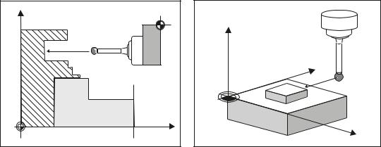
Workpiece measurement
; |
|
|
|
) |
|
|
|
= |
|
|
< |
|
|
: |
: |
= |
; |
Workpiece measurement, turning example |
Workpiece measurement, milling example |
In workpiece measurement, a probe is moved up to the clamped workpiece in the same way as a tool and the measured values are acquired. The flexibility of measuring cycles makes it possible to perform nearly all measurements required on a milling or turning machine.
The result of the workpiece measurement can be optionally used as follows:
●Compensation in the work offset
●Automatic tool offset
●Measurement without offset
Measuring cycles
Programming Manual, 03/2013, 6FC5398-4BP40-3BA1 |
9 |
Description
1.1 Basics
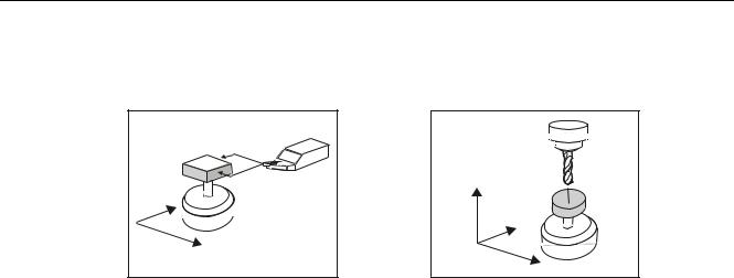
Tool measurement
|
= |
; |
|
|
< |
= |
|
|
; |
Tool measurement, turning tool example |
Tool measurement, drill example |
In tool measurement, the selected tool is moved up to the probe and the measured values are acquired. The probe is either in a fixed position or is swung into the working area with a mechanism. The tool geometry measured is entered in the appropriate tool offset data set.
|
Measuring cycles |
10 |
Programming Manual, 03/2013, 6FC5398-4BP40-3BA1 |
Description
1.2 General prerequisites
1.2General prerequisites
Certain preconditions must be met before measuring cycles can be used. These are described in detail in the SINUMERIK 840D sl Base Software and Operating Software.
Check the preconditions using the following checklist:
●Machine
–All machine axes are designed in accordance with DIN 66217.
–Machine data has been adapted.
●Starting position
–The reference points have been approached.
–The starting position can be reached by linear interpolation without collision.
●Display functions of the measuring cycles
A HMI/PCU or HMI/TCU is required for showing the measuring result displays and for measuring cycle support.
●Please observe the following when programming:
–Tool radius compensation is deselected before it is called (G40).
–The cycle is called no later than at the 5th program level.
–The measurement is also possible in a system of units that differs from the basic system (with technology data that has been switched over).
For metric dimension system with active G70, G700. For inch dimension system with active G71, G710.
References
Supplementary information for this documentation is provided in the following manuals:
●Commissioning Manual SINUMERIK 840D sl Base Software and Operating Software
– /IM9/ SINUMERIK Operate
●/PG/, Programming Manual SINUMERIK 840D sl /828D Fundamentals
●/FB1/, Function Manual Basic Functions
●/FB2/, Function Manual Expanded Functions
●/FB3/, Function Manual Special Functions
Measuring cycles |
|
Programming Manual, 03/2013, 6FC5398-4BP40-3BA1 |
11 |

Description
1.3 Behavior on block search, dry run, program testing, simulation
1.3Behavior on block search, dry run, program testing, simulation
Function
The measuring cycles are skipped during execution if one of the following execution modes is active:
• "Trial run"
• "Program test"
• "Block search"
Simulation
($P_DRYRUN=1)
($P_ISTEST=1)
($P_SEARCH=1), only if $A_PROTO=0.
The simulation of the measuring cycles is realized in the user interface (HMI) in the "Program Editor" area.
Following settings are possible in the channel-specific setting data SD 55618:
●SD 55618 $SCS_MEA_SIM_ENABLE = 0
The measuring cycle is skipped, the HMI simulation shows no path motion of the probe.
●SD 55618 $SCS_MEA_SIM_ENABLE = 1
The measuring cycle is executed, the HMI simulation shows the corresponding path motion of the probe.
No measurements, tool or work offsets are made.
Actived functions such as "measuring result display" or "travel with collision monitoring" are not implemented.
|
Measuring cycles |
12 |
Programming Manual, 03/2013, 6FC5398-4BP40-3BA1 |

Description
1.4 Reference points on the machine and workpiece
1.4Reference points on the machine and workpiece
General information
Depending on the measuring task, measured values may be required in the machine coordinate system (MCS) or in the workpiece coordinate system (WCS).
For example: It may be easier to ascertain the tool length in the machine coordinate system. Workpiece dimensions are measured in the workpiece coordinate system.
Where:
●M = machine zero in the machine coordinate system
●W = workpiece zero in the workpiece coordinate system
●F = tool reference point
Reference points
; |
|
|
|
|
|
/ |
|
|
|
|
) |
|
|
|
/ |
|
6SLQGOH |
|
|
|
FKXFN |
|
|
|
|
; |
|
|
:RUNSLHFH |
|
|
|
:2 LQ = |
|
|
|
|
: |
|
0 |
|
|
= = |
|
) |
|
= |
|
/ |
|
< |
= |
: |
|
< |
0 |
; |
|
; |
The position of tool reference point F in the machine coordinate system is defined with machine zero M as the machine actual value.
The position of the tip/cutting edge of the active tool in the workpiece coordinate system is displayed with the workpiece zero W as workpiece actual value. For a workpiece probe, the center or the end of the probe ball can be defined as the tool tip.
The work offset (WO) characterizes the position of the workpiece zero W in the machine coordinate system.
Work offsets (WO) comprise the components offset, rotation, mirroring and scaling factor (only the global basis work offset does not contain any rotation).
Measuring cycles |
|
Programming Manual, 03/2013, 6FC5398-4BP40-3BA1 |
13 |

Description
1.4 Reference points on the machine and workpiece
A distinction is made between the basis, work offset (G54 ... G599) and programmable work offset. The basic area contains further subsections – such as the basic work offset, channelspecific basic work offset and configuration-dependent work offsets (e.g. rotary table reference or basic reference).
The specified work offsets are effective together as a chain and result in the workpiece coordinate system.
Note
Scale factors with a scaling value unequal to "1" are not supported by the measuring cycles! Mirroring functions are only permitted in conjunction with counterspindles on lathes.
The machine and workpiece coordinate system can be set and programmed separately in the "inch" or "metric" measuring system.
Note
Transformation
•Measure workpiece
Workpiece measurements are always performed in the workpiece coordinate system. All descriptions relating to workpiece measurement refer to it!
•Measure tool
When measuring tools with kinematic transformation active, a distinction is made between basic coordinate system and machine coordinate system.
If kinematic transformation is deactivated, this distinction is made.
All subsequent descriptions relating to tool measurement assume that kinematic transformation is disabled and therefore refer to the machine coordinate system.
|
Measuring cycles |
14 |
Programming Manual, 03/2013, 6FC5398-4BP40-3BA1 |

Description
1.5 Definition of the planes, tool types
1.5Definition of the planes, tool types
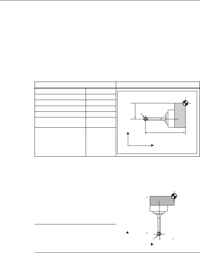
When measuring under milling, machining planes G17, G18 or G19 can be selected. When measuring under turning, machining plane G18 must be selected.
For tool measurement, the following tool types are permitted:
●Milling, type 1..
●Drill, type 2 ...
●Turning tools, type 5 ...
Depending on the tool type, the tool lengths are assigned to the axes as follows:
●Workpiece probe, milling: Probe types 710, 712, 713, 714
●Workpiece probe, turning: Probe type 580 for turning machines without extended milling technology, otherwise 710
See "Measuring the workpiece on a machine with combined technologies (Page 190)".
Milling
 =
=
*
<
*
*
; 
|
Acts in ... |
G17 plane |
G18 plane |
G19 plane |
|
Tool type: |
|
1xy / 2xy / 710 |
|
Length 1 |
1st axis of the plane: |
Z |
Y |
X |
Length 2 |
2nd axis of the plane: |
Y |
X |
Z |
Length 3 |
3rd axis of the plane: |
X |
Z |
Y |
Note:
In the assignment of the tool lengths, note the settings in the following setting data
SD42940 $SC_TOOL_LENGTH_CONST
SD42950 $SC_TOOL_LENGTH_TYPE
Measuring cycles |
|
Programming Manual, 03/2013, 6FC5398-4BP40-3BA1 |
15 |
Description
1.5 Definition of the planes, tool types
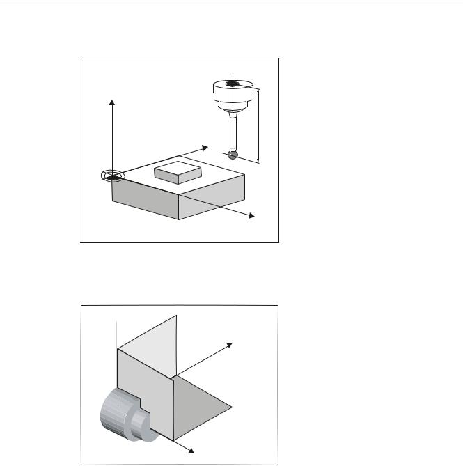
Example of plane definition for milling
) |
= |
/ |
< |
: |
; |
Figure 1-1 Example: Milling machine with G17
Turning
 <
<
;
*
=
Turning machines generally only use axes Z and X and therefore:
G18 plane |
|
Tool type |
5xy (turning tool, workpiece probe) |
Length 1 |
Acts in X (2nd axis of the plane) |
Length 2 |
Acts in Z (1st axis of the plane) |
Measuring cycles
16 |
Programming Manual, 03/2013, 6FC5398-4BP40-3BA1 |
Description
1.5 Definition of the planes, tool types
G17 and G19 are used for milling on a turning machine. If there is no machine axis Y, milling can be implemented with the following kinematic transformations.
●TRANSMIT
●TRACYL
In principle, measuring cycles support kinematic transformations. This is stated more clearly in the individual cycles and measuring variants. Information about kinematic transformation can be found in the Programming Manual SINUMERIK 840D sl /828D Fundamentals or in the documentation of the machine manufacturer.
Note
If a drill or milling cutter is measured on a lathe, in most cases, the channel-specific SD 42950 $SC_TOOL_LENGTH_TYPE = 2 is set: These tools are then length-compensated like a turning tool.
SINUMERIK controls have other machine and setting data that can influence the calculation of a tool.
References:
●/FB1/, Function Manual Basic Functions
●/FB2/, Function Manual Expanded Functions
●/FB3/, Function Manual Special Functions
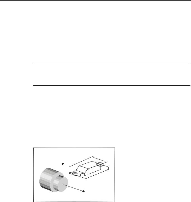
Example of plane definition for turning
/
; 
 )
) 
/
=
Figure 1-2 Example: Lathe with G18
Measuring cycles |
|
Programming Manual, 03/2013, 6FC5398-4BP40-3BA1 |
17 |

Description
1.6 Probes that can be used
1.6Probes that can be used
General information
To measure tool and workpiece dimensions, an electronic touch-trigger probe is required that provides a signal change (edge) when deflected with the required repeat accuracy.
The probe must operate virtually bounce-free.
Different types of probe are offered by different manufacturers.
Note
Please observe the information provided by the manufacturers of electronic probes and/or the machine manufacturer's instructions on the following points:
•Electrical connection
•Mechanical calibration of the probe
•If a workpiece probe is used, both the direction of deflection and transmission of switching signal to the machine column (radio, infrared light or cable) must be taken into account. In some versions, transmission is only possible in particular spindle positions or in particular ranges. This can restrict the use of the probe.
Probes are distinguished according to the number of measuring directions.
●Multi-directional (multi probe)
●Mono-directional (mono probe)
Workpiece probe |
|
Tool probe |
|
|
Multi-directional (3D) |
Mono-directional |
Milling machines |
Lathes |
|
|
< |
|
|
|
; |
; |
|
|
|
|
< |
|
|
|
|
= |
|
|
|
The probes also differ in the form of the stylus tip:
The measuring cycles support pin, L and star probes as autonomous tool types. The use of the probe types is referenced in the individual measuring cycles. The multi probe is universally applicable.
Measuring cycles
18 |
Programming Manual, 03/2013, 6FC5398-4BP40-3BA1 |
Description
1.6 Probes that can be used
The use of probes requires a spindle that can be positioned. For a mono probe, the switching direction is tracked for each measurement by turning the spindle. This can lead to a longer program runtime.
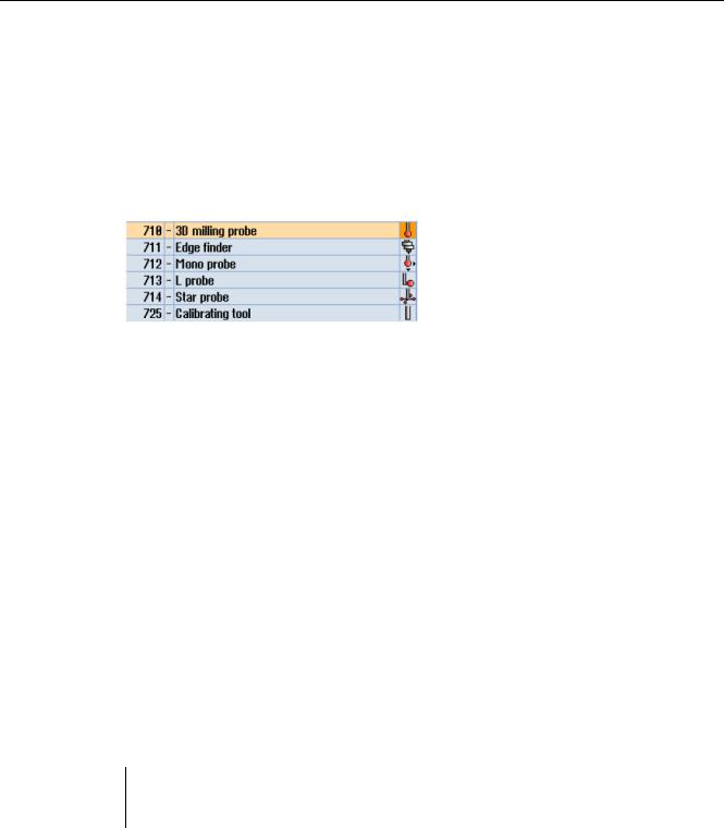
Workpiece probe types
The following probe types are provided in the tool management for measuring with workpiece probes:
Figure 1-3 Probe types in the tool management
There is a calibration tool to calibrate tool probes (type 725) = cylindrical pin
Tool data from probes
The probes differ as a result of the tool type and the switching directions in tool parameter $TC_DP25[ ] bit16 to bit 25. The switching directions are permanently coded when creating the tool.
In the application, the probe can encompass several of the following tool types. In this case, several cutting edges should be created for the probe (D1, D2, etc. ).
Example: Multi probe with a boom
D1 |
3D_PROBE |
Type 710 |
D2 |
L_PROBE |
Type 713 |
The user must take into account the geometry of the probe when pre-positioning. To do this, you can read out individual tool data in the user program:
Example:
IF (($P_TOOLNO>0) AND ($P_TOOL>0))
R1= ($P_AD[6] ;Read tool radius of the current tool
ENDIF
The probe is aligned in the + X direction using parameter offset angle.
Measuring cycles |
|
Programming Manual, 03/2013, 6FC5398-4BP40-3BA1 |
19 |
Description
1.6 Probes that can be used
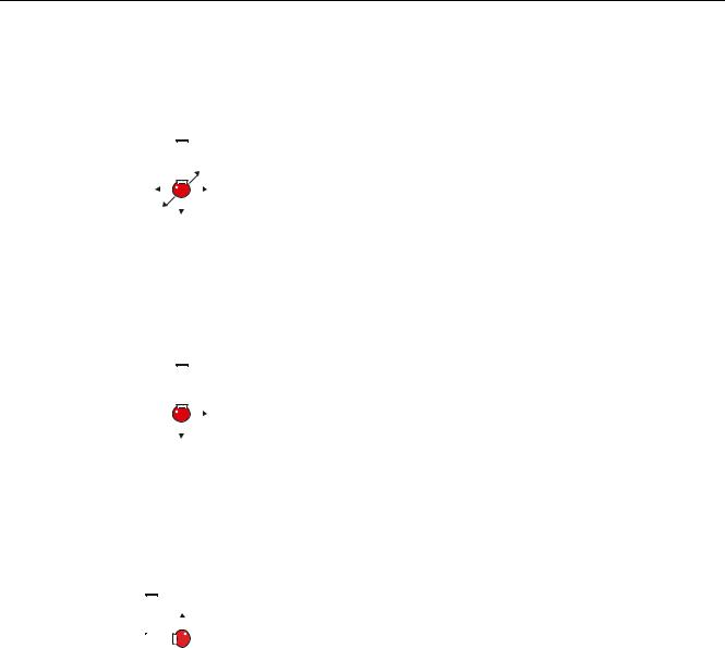
3D_PROBE (multi probe)
Display |
|
|
|
|
|
Properties |
Characteristic |
||
|
|
|
|
|
|
|
|
Application: |
Universal |
|
|
|
|
|
|
|
|
Type: |
$TC_DP1[ ]=710 |
|
|
|
|
< |
Tool length: |
In Z (for G17) |
|||
|
|
|
|
|
|
|
|
||
|
|
|
|
|
|
|
|
||
; |
|
|
|
|
|
Offset angle: |
$TC_DP10[ ] = 0 |
||
|
|
; |
|||||||
< |
|
|
|
|
|
|
|
||
|
|
|
|
|
|
|
|||
|
|
|
|
|
|
|
|
|
|
|
|
|
= |
|
|
|
|
|
|
|
|
|
|
|
|
|
|
|
|
MONO PROBE
Display |
|
|
|
|
|
Properties |
Characteristic |
|
|
|
|
|
|
Application: |
Alignment of the switching direction when |
|
|
|
|
|
|
|
measuring |
|
|
|
|
|
|
Type: |
$TC_DP1[ ]=712 |
|
|
|
|
|
|
Tool length: |
In Z (for G17) |
|
; |
|
|
||||
|
|
|
|
|
|
|
|
|
|
|
|
|
|
Offset angle: |
$TC_DP10[ ] = 0 to 359.9 degrees |
|
= |
|
|
|
|||
|
|
|
|
|
|
||
|
|
|
|
|
|
|
|
L_PROBE
Display |
Properties |
Characteristic |
||||
|
|
|
|
|
Application: |
Towing measurement in +Z |
|
|
= |
Type: |
$TC_DP1[]=713 |
||
|
|
|||||
|
|
|
|
|
Tool length: |
In Z (for G17) |
|
|
|
|
|
||
|
|
|
|
|
||
|
|
|
|
|
Offset angle: |
$TC_DP10[ ] = 0 to 359.9 degrees |
|
|
|
|
|
||
|
|
|
|
|
Radius in the plane |
$TC_DP6[ ] |
|
|
|
|
|
(length of the boom): |
|
|
|
|
|
|
Radius of the probe ball in |
$TC_DP7[ ] |
|
|
|
|
|
the tool direction: |
|
The tool length is defined as the length between the tool reference point in the holder and the contact point in the +Z direction of the probe ball.
|
Measuring cycles |
20 |
Programming Manual, 03/2013, 6FC5398-4BP40-3BA1 |
Description
1.6 Probes that can be used
STAR PROBE
Display |
|
|
|
Properties |
Characteristic |
|||||||
|
|
|
|
|
|
|
|
|
|
|
Application: |
Measure hole parallel to the axis 1) |
|
|
|
|
|
|
|
|
< |
|
|
|
|
|
|
|
|
|
|
|
|
|
|
|
Type: |
$TC_DP1[ ]=714 |
; |
|
|
|
|
|
|
|
|
|
|
Tool length: |
In Z (for G17) |
|
|
|
|
|
|
|
|
|
|
|||
|
|
|
|
|
|
|
|
|
|
|
Offset angle: |
$TC_DP10[ ] = 0 to 359.9 degrees |
|
|
|
|
|
|
|
|
|
|
|
||
|
|
|
|
|
|
|
|
|
|
|
||
|
|
|
|
|
|
|
|
|
|
|
||
|
|
|
|
|
|
|
|
|
|
; |
Radius in the plane |
$TC_DP6[ ] |
|
|
|
|
|
|
|
|
|
|
|||
|
|
|
|
|
|
|
|
|
|
|
||
|
|
|
|
|
|
|
|
|
|
|
(diameter of the star |
|
< |
|
|
|
|
|
|
|
|
|
parallel to the axis): |
|
|
|
|
|
|
|
|
|
|
|
|
|
|
|
|
|
|
|
|
|
|
|
|
|
|
Radius of the probe ball in |
$TC_DP7[ ] |
|
|
|
|
|
|
|
|
|
|
|
the tool direction: |
|
1)The applications only refer to measurements in the plane (for G17 XY). Measurement in the tool direction is not permitted using a star probe. If a measurement is to be made in the tool direction, a star element (boom) must be declared as an L probe.
The tool length is defined as the length between the tool reference point in the holder and the probe ball center point (equator) of one of the measuring balls.
Assignment of the probe types
Probe type |
|
Lathes |
Milling and machining centers |
|
|
Tool measurement |
|
Workpiece measurement |
Workpiece measurement |
Multi-directional |
X |
|
X |
X |
Mono-directional |
-- |
|
-- |
X |
Measuring cycles |
|
Programming Manual, 03/2013, 6FC5398-4BP40-3BA1 |
21 |

Description
1.7 Probe, calibration body, calibration tool
1.7Probe, calibration body, calibration tool
1.7.1Measuring workpieces on milling machines, machining centers
Probe calibration
All probes must be mechanically correctly adjusted before use. The switching directions must be calibrated before they are used in the measuring cycles for first-time. This also applies when changing the stylus tip of the probe.
When being calibrated, the trigger points (switching points), position deviation (skew), and active ball radius of the workpiece probe are determined and entered into the data fields of the general setting data SD 54600 $SNS_MEA_WP_BALL_DIAM . There are 12 data fields.
Calibration can be realized in a calibration ring (known bore), on a calibration ball or on workpiece surfaces, which have an appropriate geometrical precision and low surface roughness.
Use the same measuring velocity for calibrating and measuring. This applies in particular to the feedrate overide.
Measuring cycle CYCLE976 with different measuring versions is available to calibrate the probe.
See also
Calibrate probe - length (CYCLE976) (Page 85)
Calibrate probe - radius in ring (CYCLE976) (Page 89)
Calibrate probe - radius on edge (CYCLE976) (Page 92)
Calibrate probe - calibrate on ball (CYCLE976) (Page 95)
|
Measuring cycles |
22 |
Programming Manual, 03/2013, 6FC5398-4BP40-3BA1 |
Description
1.7 Probe, calibration body, calibration tool
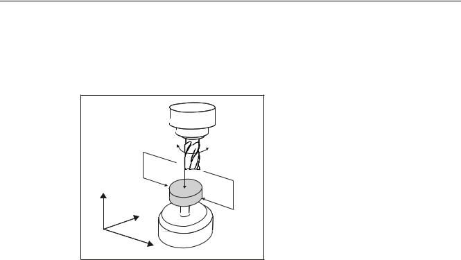
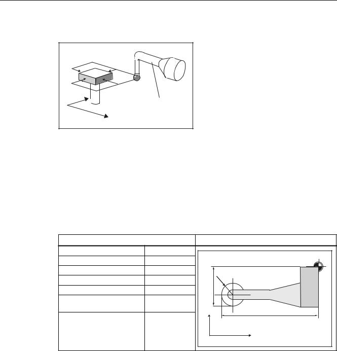
1.7.2Measuring tools on milling machines, machining centers
Tool probe
=
<
;
Figure 1-4 Measuring a milling cutter
Tool probes have their own data fields in the general setting data:
●For machine-related measurement/calibration:
–SD 54625 $SNS_MEA_TP_TRIG_MINUS_DIR_AX1
–SD 54626 $SNS_MEA_TP_TRIG_PLUS_DIR_AX1
–SD 54627 $SNS_MEA_TP_TRIG_MINUS_DIR_AX2
–SD 54628 $SNS_MEA_TP_TRIG_PLUS_DIR_AX2
●For workpiece-related measurement/calibration:
–SD 54640 $SNS_MEA_TPW_TRIG_MINUS_DIR_AX1
–SD 54641 $SNS_MEA_TPW_TRIG_PLUS_DIR_AX1
–SD 54642 $SNS_MEA_TPW_TRIG_MINUS_DIR_AX2
–SD 54643 $SNS_MEA_TPW_TRIG_PLUS_DIR_AX2
The triggering points (switching points), upper disk diameter and edge length are entered here.
Approximate values must be entered here before calibration – if cycles are used in automatic mode. The cycle will then recognize the position of the probe.
The default setting has data fields for three probes. Up to 99 are possible.
Measuring cycles |
|
Programming Manual, 03/2013, 6FC5398-4BP40-3BA1 |
23 |
Description
1.7 Probe, calibration body, calibration tool
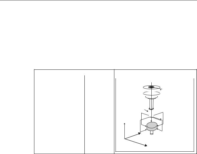
Calibration, calibration tool
A probe must be calibrated before it can be used. Calibration involves precisely determining the triggering points (switching points) of the tool probe and entering them in special data fields.
Calibration is performed with a calibration tool. The precise dimensions of the tool are known.
Use the same measuring velocity for calibrating and measuring.
Measurement version Calibrate probe (CYCLE971) (Page 218) is ready for calibration.
Entry in tool memory |
|
|
Calibrating tool probes |
|
|
|
|
|||
Tool type ($TC_DP1[ ]): |
1xy |
|
|
|
|
|
|
|
|
|
|
|
|
|
|
|
|
|
|
||
Length 1 - geometry |
L1 |
|
|
|
|
|
) |
|
|
|
($TC_DP3[ ]): |
|
|
|
|
|
|
|
|
|
|
|
|
|
|
|
|
|
|
|
|
|
|
|
|
|
|
|
|
|
|
|
|
Radius ($TC_DP6[ ]): |
r |
|
|
|
|
|
|
|
|
|
|
|
|
|
|
|
|
|
|
||
|
|
|
|
|
|
|
|
|
||
|
|
|
|
|
|
|
|
|||
Length 1 - basic dimension |
only if required |
|
&DOLEUDWLRQ WRRO |
|
|
|
|
|||
($TC_DP21[ ]): |
|
|
|
|
|
|
|
/ |
|
|
|
|
|
|
|
|
|
|
|
|
|
|
|
|
U |
|
|
|
|
|
||
|
|
|
|
|
|
|
|
|
|
|
|
|
|
|
|
|
|
|
|
|
|
 =
=
<
7RRO SUREH
;
The wear and other tool parameters must be assigned the value 0.
|
Measuring cycles |
24 |
Programming Manual, 03/2013, 6FC5398-4BP40-3BA1 |
Description
1.7 Probe, calibration body, calibration tool
1.7.3Measuring workpieces at the turning machines
Workpiece probe
On turning machines, the workpiece probes are treated as tool type 5xy with permissible cutting edge positions (SL) 5 to 8 and must be entered in the tool memory accordingly.
Lengths specified for turning tools always refer to the tool tip, except in the case of workpiece probes on turning machines where they refer to the probe center.
Probes are classified according to their position:
Workpiece probe SL 7
Entry in tool memory |
|
Workpiece probe for a lathe |
|
Tool type ($TC_DP1[ ]): |
5xy |
|
|
Cutting edge ($TC_DP2[ ]): |
7 |
) |
|
Length 1 |
- geometry: |
L1 |
|
Length 2 |
- geometry: |
L2 |
/ |
Radius ($TC_DP6[ ]): |
r |
U |
|
Length 1 |
- basic dimension |
only if required |
|
($TC_DP21[ ]): |
only if required |
|
|
Length 2 |
- basic dimension |
/ |
|
($TC_DP22[ ]): |
|
; |
|
|
|
|
= |
The wear and other tool parameters must be assigned the value 0.
Workpiece probe SL 8
Entry in tool memory |
|
Workpiece probe for a lathe |
|
|
|
|
|
|||||||||
Tool type ($TC_DP1[ ]): |
5xy |
|
|
|
|
|
|
|
|
|
|
|
|
|
|
|
|
|
|
|
|
|
|
|
|
|
|
|
|
|
|||
Cutting edge ($TC_DP2[ ]): |
8 |
|
|
|
|
|
|
|
|
|
) |
|
|
|||
|
|
|
|
|
|
|
|
|
|
|
|
|
|
|||
Length 1 |
- geometry: |
L1 |
|
|
|
|
|
|
|
|
|
|
|
|
|
|
|
|
|
|
|
|
|
|
|
|
|
|
|
|
|||
Length 2 |
- geometry: |
L2 |
|
|
|
|
|
|
|
|
|
|
|
|
|
|
|
|
|
|
|
|
|
|
|
|
|
|
|
|
|||
Radius ($TC_DP6[ ]): |
r |
|
|
/ |
|
|
|
|
|
|
|
|
|
|
|
|
Length 1 |
- basic dimension |
only if required |
|
|
|
|
|
|
|
|
|
|
|
|
|
|
($TC_DP21[ ]): |
|
|
|
|
|
|
|
|
|
|
|
|
|
|
|
|
Length 2 |
- basic dimension |
only if required |
|
|
|
|
|
|
|
|
|
|
|
|
|
|
($TC_DP22[ ]): |
|
|
|
|
|
|
|
|
|
|
/ |
|
|
|
|
|
|
|
|
|
|
|
|
|
|
|
|
|
|
|
|||
|
|
|
|
|
|
|
|
|
|
|
|
|
|
|
|
|
|
|
|
|
|
|
|
|
|
|
|
|
|
|
|||
|
|
|
|
|
|
|
|
U |
|
|
|
|
|
|
||
|
|
|
|
; |
|
|
|
|
|
|
|
|
|
|
|
|
|
|
|
|
|
|
|
|
|
|
|
|
|
|
|
|
|
|
|
|
|
|
= |
|
|
|
|
|
|
|
|
|
||
|
|
|
|
|
|
|
|
|
|
|
|
|
|
|
|
|
|
|
|
|
|
|
|
|
|
|
|
|
|
|
|
|
|
The wear and other tool parameters must be assigned the value 0.
Measuring cycles
Programming Manual, 03/2013, 6FC5398-4BP40-3BA1 |
25 |

Description |
|
|
|
|
1.7 Probe, calibration body, calibration tool |
|
|
|
|
Workpiece probe SL 5 or SL 6 |
|
|
|
|
Entry in tool memory |
|
Workpiece probe for a lathe |
|
|
Tool type ($TC_DP1[ ]): |
5xy |
|
|
|
Cutting edge ($TC_DP2[ ]): |
5 or 6 |
|
|
|
Length 1 - geometry: |
L1 |
6/ |
|
6/ |
|
|
|
||
Length 2 - geometry: |
L2 |
|
U |
/ |
) |
|
|
||
|
|
|
||
Radius ($TC_DP6[ ]): |
r |
/ |
|
|
Length 1 - basic dimension |
only if required |
|
|
|
($TC_DP21[ ]): |
|
U |
/ |
|
Length 2 - basic dimension |
only if required |
/ |
|
|
|
|
|
||
($TC_DP22[ ]): |
|
|
|
|
|
|
; |
|
) |
|
|
= |
|
|
The wear and other tool parameters must be assigned the value 0.
Calibration, gauging block
; |
) |
|
|
|
; |
|
|
= = |
|
: |
|
0 |
|
|
Figure 1-5 Calibrating a workpiece probe, example: Calibrating in the reference groove
A probe must be calibrated before it can be used. When being calibrated, the trigger points (switching points), position deviation (skew), and precise ball radius of the workpiece probe are determined and entered into the corresponding data fields of the general setting data SD 54600 $SNS_MEA_WP_BALL_DIAM .
The default setting has data fields for 12 probes.
Measuring cycles
26 |
Programming Manual, 03/2013, 6FC5398-4BP40-3BA1 |

Description
1.7 Probe, calibration body, calibration tool
Calibration of the workpiece probe on turning machines is usually performed with gauging blocks (reference grooves). The precise dimensions of the reference groove are known and entered in the associated data fields of the following general setting data:
●SD54615 $SNS_MEA_CAL_EDGE_BASE_AX1
●SD54616 $SNS_MEA_CAL_EDGE_UPPER_AX1
●SD54617 $SNS_MEA_CAL_EDGE_PLUS_DIR_AX1
●SD54618 $SNS_MEA_CAL_EDGE_MINUS_DIR_AX1
●SD54619 $SNS_MEA_CAL_EDGE_BASE_AX2
●SD54620 $SNS_MEA_CAL_EDGE_UPPER_AX2
●SD54621 $SNS_MEA_CAL_EDGE_PLUS_DIR_AX2
●SD54622 $SNS_MEA_CAL_EDGE_MINUS_DIR_AX2
The default setting has data fields for three gauging blocks. In the measuring cycle program, the selection is made using the number of the gauging block (S_CALNUM).
It is also possible to calibrate on a known surface.
Measuring cycle CYCLE973 with various measuring versions is ready for calibration.
See also
Calibrate probe - length (CYCLE973) (Page 59)
Calibrate probe - radius on surface (CYCLE973) (Page 62)
Calibrate probe - calibrate in groove (CYCLE973) (Page 65)
Measuring cycles |
|
Programming Manual, 03/2013, 6FC5398-4BP40-3BA1 |
27 |

Description
1.7 Probe, calibration body, calibration tool
1.7.4Measuring tools at lathes
Tool probe
0HDVXUH OHQJWK |
0HDVXUH OHQJWK |
; |
= |
Figure 1-6 Measuring a turning tool
Tool probes have their own data fields in the general setting data:
●For machine-related measurement/calibration:
–SD 54626 $SNS_MEA_TP_TRIG_PLUS_DIR_AX1
–SD 54625 $SNS_MEA_TP_TRIG_MINUS_DIR_AX1
–SD 54627 $SNS_MEA_TP_TRIG_MINUS_DIR_AX2
–SD 54628 $SNS_MEA_TP_TRIG_PLUS_DIR_AX2
●For workpiece-related measurement/calibration:
–SD 54641 $SNS_MEA_TPW_TRIG_PLUS_DIR_AX1
–SD 54640 $SNS_MEA_TPW_TRIG_MINUS_DIR_AX1
–SD 54642 $SNS_MEA_TPW_TRIG_MINUS_DIR_AX2
–SD 54643 $SNS_MEA_TPW_TRIG_PLUS_DIR_AX2
The triggering points (switching points) are entered here. Approximate values must be entered here before calibration – if cycles are used in automatic mode. The cycle will then recognize the position of the probe.
The default setting has data fields for 6 probes.
In addition to turning tools, drills and mills can also be measured.
Measuring cycles
28 |
Programming Manual, 03/2013, 6FC5398-4BP40-3BA1 |
Description
1.7 Probe, calibration body, calibration tool
Calibration, gauging block
; |
|
|
&DOLEUDWLRQ WRRO |
|
= |
A probe must be calibrated before it can be used. Calibration involves precisely determining the triggering points (switching points) of the tool probe and entering them in special data fields.
Calibration is performed with a calibration tool. The precise dimensions of the tool are known.
Measurement version Calibrate probe (CYCLE982) (Page 194) is ready for calibration.
For lathes, the calibration tool is treated like a turning tool with cutting edge position 3. The lengths refer to the ball circumference, not to the ball center.
Entry in tool memory |
|
Calibration tool for a tool probe on a lathe |
|
Tool type ($TC_DP1[ ]): |
5xy |
|
|
Cutting edge ($TC_DP2[ ]): |
3 |
) |
|
Length 1 |
- geometry: |
L1 |
|
Length 2 |
- geometry: |
L2 |
U |
Radius ($TC_DP6[ ]): |
r |
/ |
|
|
|||
Length 1 |
- basic dimension |
only if required |
|
($TC_DP21[ ]): |
|
|
|
Length 2 |
- basic dimension |
only if required |
/ |
; |
|||
($TC_DP22[ ]): |
|
|
|
|
|
|
= |
The wear and other tool parameters must be assigned the value 0.
Measuring cycles
Programming Manual, 03/2013, 6FC5398-4BP40-3BA1 |
29 |
Description
1.8 Measurement principle
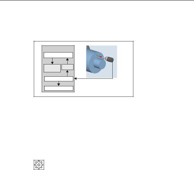
1.8Measurement principle
Flying measurement
1& |
|
0HDVXULQJ F\FOH |
|
'HOHWH |
$FWXDO |
GLVWDQFH WR |
YDOXH |
JR |
|
$FWXDO YDOXH DFTXLVLWLRQ |
|
3RVLWLRQ FRQWURO |
|
The principle of "flying measurement" is implemented in the SINUMERIK control. The probe signal is processed directly on the NC so that the delay when acquiring measured values is minimal. This permits a higher measuring speed for the prescribed measuring precision and time needed for measuring is reduced.
Connecting probes
Two inputs for connecting touch trigger probes are provided on the I/O device interface of the SINUMERIK control systems.
Machine manufacturer
Please observe the machine manufacturer’s instructions.
Measuring cycles
30 |
Programming Manual, 03/2013, 6FC5398-4BP40-3BA1 |
Loading...