


SINUMERIK 840D/810D SIMODRIVE 611 digital
Start-Up Guide
Valid for |
|
|
Control |
Version |
|
SINUMERIK 840D/810D powerline |
6 |
|
SINUMERIK 840DE/810DE powerline |
|
|
|
(export variant) |
6 |
Drive |
Version |
|
SIMODRIVE 611 digital |
5 |
|
03/2006 Edition
General preparation
Structure
Settings, MPI/BTSS
EMC/ESD measures
Power-On and Power-Up
Programming the control
PLC description
Alarm and message texts
Axis/spindle test run
Drive optimization
Data back-up
Replacing software and hardware
HMI
Miscellaneous
Abbreviations
Index
1
2
3
4
5
6
7
8
9
10
11
12
13
14
A

3ls |
SINUMERIK→ documentation |
|
Key to editions
The editions listed below have appeared before this edition.
The letters in the “Note” column indicate which status the previously published editions have.
Identification of the status in the “Notes” column:
A . . . . . New documentation.
B . . . . . Unchanged reprint with new order number.
C . . . . . Revised version with new edition number.
Edition |
Order no. |
Notes |
03/2006 |
6FC5 297-6AB20-0BP0 |
A |
Trademarks |
→ are registered trademarks of Siemens AG. The other |
All designations identified with the trademark note |
designations in this publications may be trademarks, the use of which by third parties for their own purposes may infringe the rights of the owner.
Exclusion of liability
We have checked the content of the document to ensure that it conforms to the described hardware and software. Nevertheless, the possibility of differences cannot be totally excluded, so we are unable to guarantee that it conforms totally. However, the information in this document is checked regularly and necessary corrections are included in the subsequent editions.
Copyright E Siemens AG 2006
Order no: 6FC5297-6AB20-0BP0
Siemens AG 2006
Subject to technical modifications.
Preface
Structure of the documentation
Target group
Benefits
Standard scope
The SINUMERIK documentation is divided into three levels:
SGeneral documentation
SUser documentation
SManufacturer/service documentation
A monthly updated list of publications with the available language versions can be found on the Internet at:
http://www.siemens.com/motioncontrol
Follow the menu options “Support” → “Technical Documentation” → “List of Publications”.
The Internet edition of the DOConCD – the DOConWEB – can be found at: http://www.automation.siemens.com/doconweb
Information about training courses and FAQs (frequently-asked questions) can be found on the Internet at:
http://www.siemens.com/motioncontrol , select the “Support” option.
This documentation is intended for use by start-up engineers.
The Start-Up Guide will enable the intended target group to test the product/ system or plant and to bring it into service correctly and safely.
This Start-Up Guide describes the functionality of the standard scope. Additions or modifications made by the machine manufacturer will be documented by the machine manufacturer.
Other functions not explained in this document may also run on the control. However, no claims to these functions exist in the event of replacement and/or maintenance.
For the sake of clarity, this documentation does not contain all the detailed information about all types of the product, and also cannot take account of every possible situation for installation, operation and maintenance.
♥ Siemens AG 2006 All Rights Reserved |
iii |
SINUMERIK 840D/810D Start-Up Guide (IADC) – 03/2006 Edition |

Preface |
03/2006 |
Technical Support If you have any questions, please contact the following hotline:
Europe and Africa time zones:
A&D Technical Support
Tel.: +49 (0) 180 / 5050 – 222
Fax: +49 (0) 180 / 5050 – 223
Internet: http://www.siemens.com/automation/support-request
E-Mail: mailto:adsupport@siemens.com
Asia and Australia time zones:
A&D Technical Support
Tel.: +86 1064 719 990
Fax: +86 1064 747 474
Internet: http://www.siemens.com/automation/support-request
E-Mail: mailto:adsupport@siemens.com
America time zone:
A&D Technical Support
Tel.: +1 423 262 2522
Fax: +1 423 262 2289
Internet: http://www.siemens.com/automation/support-request
E-Mail: mailto:adsupport@siemens.com
Note
Questions about this Guide
Country-specific telephone numbers for technical advice can be found on the Internet:
http://www.siemens.com/automation/service&support
If you have any questions about the documentation (suggestions or corrections), please send a fax or e-mail to the following address:
Fax: +49 (0) 9131 / 98 – 63315
E-Mail: mailto:motioncontrol.docu@siemens.com
Fax form: see Feedback sheet at the end of this document.
SINUMERIK |
http://www.siemens.com/sinumerik |
web site |
|
EU Declaration of |
The EU Declaration of Conformity about the EMC Directive can be found/ |
Conformity |
obtained |
|
S on the Internet: |
|
http://www.ad.siemens.com/csinfo |
|
under product/order number 15257461 |
|
S from the responsible branch of the A&D MC Division of Siemens AG |
Object of the book |
The publication illustrates the structure of the control system and the interfaces |
|
to the individual components. It also describes the procedure for starting up |
|
SINUMERIK 810D, and lists all the data, signals and PLC modules. |
iv |
♥ Siemens AG 2006 All Rights Reserved |
SINUMERIK 840D/810D Start-Up Guide (IADC) – 03/2006 Edition |

03/2006 |
Preface |
User-oriented activities such as the creation of part programs and control operation procedures are described in detail in separate documents.
Separate descriptions are likewise provided for the tasks to be performed by the tool manufacturer such as configuring, installation and PLC programming.
Safety instructions This manual contains instructions that you must follow to ensure your own personal safety and to avoid damage to property. The instructions that concern your personal safety are indicated by a warning triangle. Instructions that concern only damage to property have no warning triangle. The warnings labels are illustrated in descending order according to the level of risk.
Danger
!means that death or severe injury will occur if the specified precautionary measures are not taken.
Warning
!means that death or severe injury may occur if the specified precautionary measures are not taken.
Caution
!with warning triangle means that slight injury may occur if the specified precautionary measures are not taken.
Caution
without a warning triangle means that damage to property may occur if the specified precautionary measures are not taken.
Notice
means that an unwanted result or state may occur if the specified instructions are not followed.
If several levels of risk apply, the warning instructions always indicate the highest level. If a warning of personal injury is given in a warning notice with the warning triangle, there may also be a warning about damage to property in the same warning notice.
♥ Siemens AG 2006 All Rights Reserved |
v |
SINUMERIK 840D/810D Start-Up Guide (IADC) – 03/2006 Edition |

Preface |
03/2006 |
Qualified |
The associated device/system must only be set up and operated in conjunction |
personnel |
with this documentation. A device/system must only be brought into service and |
|
operated by qualified personnel. Qualified personnel as specified in the safety |
|
instructions in this documentation are people who are authorized to bring into |
|
service, earth and identify devices, systems and power circuits in accordance |
|
with the recognized safety standards. |
Use as prescribed |
Please note the following points: |
Warning
!The device must only be used for the purposes described in the catalog and in the technical description, and then only in conjunction with non-Siemens devices and components that are recommended or approved by Siemens. Correct and safe operation of the product requires it to have been transported, stored, installed and assembled correctly and carefully operated and maintained.
Further notes
Note
The “Note” symbol is displayed in this document to draw your attention to information relevant to the subject.
Technical information
Notations |
The following notations and abbreviations are used in this documentation: |
|
S PLC interface signals –> NST “signal name” (signal data) |
|
Examples: |
|
– IS “MMC CPU1 ready” (DB10, DBX108.2), i.e. the signal is stored in data |
|
block 10, data byte 108, bit 2. |
|
– IS “Feedrate override” (DB31, ... DBB0), i.e. the signals are stored in |
|
data blocks 31 to 38, data block byte 0. |
|
S Machine data –> MD: NUMMER, MD_NAME (German designation) |
|
S Setting data –> SD: NUMMER, SD_NAME (German designation) |
|
S The character “8” means “corresponds to”. |
|
J |
vi |
♥ Siemens AG 2006 All Rights Reserved |
SINUMERIK 840D/810D Start-Up Guide (IADC) – 03/2006 Edition |
Contents
1 |
General preparation . . . . . . . . . . . . . . . . . . . . . . . . . . . . . . . . . . . . . . . . . . . . . . . . . |
1-13 |
|
|
1.1 |
Preconditions . . . . . . . . . . . . . . . . . . . . . . . . . . . . . . . . . . . . . . . . . . . . . . . |
1-13 |
|
1.2 |
Standard/export variants . . . . . . . . . . . . . . . . . . . . . . . . . . . . . . . . . . . . . . |
1-14 |
2 |
Structure |
. . . . . . . . . . . . . . . . . . . . . . . . . . . . . . . . . . . . . . . . . . . . . . . . . . . . . . . . . . . . |
2-17 |
3 |
Settings, MPI/BTSS . . . . . . . . . . . . . . . . . . . . . . . . . . . . . . . . . . . . . . . . . . . . . . . . . . |
3-19 |
|
|
3.1 |
MPI network rules for SINUMERIK 840D . . . . . . . . . . . . . . . . . . . . . . . . |
3-19 |
|
3.1.1 |
Communication equipment . . . . . . . . . . . . . . . . . . . . . . . . . . . . . . . . . . . |
3-21 |
|
3.2 |
MPI network rules for SINUMERIK 810D . . . . . . . . . . . . . . . . . . . . . . . . |
3-24 |
|
3.3 |
MPI default configuration for SINUMERIK 840D . . . . . . . . . . . . . . . . . . |
3-26 |
|
3.4 |
MPI default configuration for SINUMERIK 810D . . . . . . . . . . . . . . . . . . |
3-28 |
|
3.5 |
Deviation from standard configuration . . . . . . . . . . . . . . . . . . . . . . . . . . |
3-30 |
|
3.6 |
MPI interface for customer’s operating panel . . . . . . . . . . . . . . . . . . . . |
3-31 |
|
3.7 |
2nd machine control panel . . . . . . . . . . . . . . . . . . . . . . . . . . . . . . . . . . . . |
3-32 |
|
3.8 |
PCU 20/50/50.3/70 . . . . . . . . . . . . . . . . . . . . . . . . . . . . . . . . . . . . . . . . . . |
3-33 |
|
3.8.1 |
Settings with HMI Embedded/HMI Advanced for SINUMERIK 840D |
3-33 |
|
3.8.2 |
Settings with HMI Embedded/HMI Advanced for SINUMERIK 810D |
3-34 |
4 |
EMC and ESD Measures . . . . . . . . . . . . . . . . . . . . . . . . . . . . . . . . . . . . . . . . . . . . . |
4-35 |
|
|
4.1 |
RI suppression measures . . . . . . . . . . . . . . . . . . . . . . . . . . . . . . . . . . . . . |
4-35 |
|
4.2 |
ESD measures . . . . . . . . . . . . . . . . . . . . . . . . . . . . . . . . . . . . . . . . . . . . . . |
4-36 |
|
4.3 |
Heat dissipation . . . . . . . . . . . . . . . . . . . . . . . . . . . . . . . . . . . . . . . . . . . . . |
4-36 |
5 |
Power-On and Power-Up . . . . . . . . . . . . . . . . . . . . . . . . . . . . . . . . . . . . . . . . . . . . . |
5-37 |
|
|
5.1 |
Start-up order . . . . . . . . . . . . . . . . . . . . . . . . . . . . . . . . . . . . . . . . . . . . . . . |
5-37 |
|
5.2 |
NCU controls and displays . . . . . . . . . . . . . . . . . . . . . . . . . . . . . . . . . . . . |
5-38 |
|
5.3 |
CCU controls and displays . . . . . . . . . . . . . . . . . . . . . . . . . . . . . . . . . . . . |
5-39 |
|
5.4 |
Power-On and Power-Up . . . . . . . . . . . . . . . . . . . . . . . . . . . . . . . . . . . . . |
5-40 |
|
5.4.1 |
Power-On . . . . . . . . . . . . . . . . . . . . . . . . . . . . . . . . . . . . . . . . . . . . . . . . . . |
5-40 |
|
5.4.2 |
Power-Up . . . . . . . . . . . . . . . . . . . . . . . . . . . . . . . . . . . . . . . . . . . . . . . . . . . |
5-41 |
|
5.4.3 |
PCU power-up . . . . . . . . . . . . . . . . . . . . . . . . . . . . . . . . . . . . . . . . . . . . . . |
5-44 |
|
5.4.4 |
Error while Control power-up . . . . . . . . . . . . . . . . . . . . . . . . . . . . . . . . . . |
5-45 |
|
5.4.5 |
Power-up of machine control panel (MSTT) . . . . . . . . . . . . . . . . . . . . . |
5-46 |
|
5.4.6 |
Powering up the drives . . . . . . . . . . . . . . . . . . . . . . . . . . . . . . . . . . . . . . . |
5-46 |
|
5.4.7 |
PCU/HMI Advanced BIOS setup . . . . . . . . . . . . . . . . . . . . . . . . . . . . . . . |
5-47 |
♥ Siemens AG 2006 All Rights Reserved |
vii |
SINUMERIK 840D/810D Start-Up Guide (IADC) – 03/2006 Edition |
Contents |
03/2006 |
6 |
Programming the control . . . . . . . . . . . . . . . . . . . . . . . . . . . . . . . . . . . . . . . . . . . . |
6-49 |
|
|
6.1 |
Machine and setting data . . . . . . . . . . . . . . . . . . . . . . . . . . . . . . . . . . . . . |
6-49 |
|
6.2 |
Handling machine and setting data . . . . . . . . . . . . . . . . . . . . . . . . . . . . . |
6-52 |
|
6.3 |
Protection level concept . . . . . . . . . . . . . . . . . . . . . . . . . . . . . . . . . . . . . . |
6-53 |
|
6.3.1 |
Protection levels for NC language commands (REDEF) . . . . . . . . . . . |
6-55 |
|
6.3.2 |
Configurable parameter areas for GUD blocks . . . . . . . . . . . . . . . . . . . |
6-57 |
|
6.4 |
Display filter for machine data . . . . . . . . . . . . . . . . . . . . . . . . . . . . . . . . . |
6-61 |
|
6.4.1 |
Function . . . . . . . . . . . . . . . . . . . . . . . . . . . . . . . . . . . . . . . . . . . . . . . . . . . . |
6-61 |
|
6.4.2 |
Selecting and setting the display filter . . . . . . . . . . . . . . . . . . . . . . . . . . . |
6-61 |
|
6.5 |
Example of a start-up concept . . . . . . . . . . . . . . . . . . . . . . . . . . . . . . . . . |
6-64 |
|
6.6 |
System data . . . . . . . . . . . . . . . . . . . . . . . . . . . . . . . . . . . . . . . . . . . . . . . . |
6-67 |
|
6.6.1 |
Basic settings . . . . . . . . . . . . . . . . . . . . . . . . . . . . . . . . . . . . . . . . . . . . . . . |
6-67 |
|
6.7 |
Memory configuration . . . . . . . . . . . . . . . . . . . . . . . . . . . . . . . . . . . . . . . . |
6-71 |
|
6.7.1 |
Dynamic RAM . . . . . . . . . . . . . . . . . . . . . . . . . . . . . . . . . . . . . . . . . . . . . . . |
6-73 |
|
6.7.2 |
Static RAM . . . . . . . . . . . . . . . . . . . . . . . . . . . . . . . . . . . . . . . . . . . . . . . . . |
6-73 |
|
6.8 |
Scaling machine data . . . . . . . . . . . . . . . . . . . . . . . . . . . . . . . . . . . . . . . . |
6-76 |
|
6.9 |
Axes and spindles . . . . . . . . . . . . . . . . . . . . . . . . . . . . . . . . . . . . . . . . . . . |
6-78 |
|
6.9.1 |
Description of the axis configuration . . . . . . . . . . . . . . . . . . . . . . . . . . . . |
6-78 |
|
6.9.2 |
Drive configuration (VSA, SLM, HSA) . . . . . . . . . . . . . . . . . . . . . . . . . . |
6-82 |
|
6.9.3 |
Programming axis-specific setpoint/actual values . . . . . . . . . . . . . . . . |
6-85 |
|
6.9.4 |
Setting drive parameters (FDD, MSD) . . . . . . . . . . . . . . . . . . . . . . . . . . |
6-87 |
|
6.9.5 |
Parameter settings for incremental measuring systems . . . . . . . . . . . |
6-89 |
|
6.9.6 |
Parameter settings for absolute measuring systems (EnDat interface) |
6-92 |
|
6.9.7 |
Overview of the drive parameters . . . . . . . . . . . . . . . . . . . . . . . . . . . . . . |
6-95 |
|
6.9.8 |
Axis data . . . . . . . . . . . . . . . . . . . . . . . . . . . . . . . . . . . . . . . . . . . . . . . . . . . |
6-99 |
|
6.9.9 |
Axis velocity matching . . . . . . . . . . . . . . . . . . . . . . . . . . . . . . . . . . . . . . . . |
6-102 |
|
6.9.10 |
Axis position control data . . . . . . . . . . . . . . . . . . . . . . . . . . . . . . . . . . . . . |
6-103 |
|
6.9.11 |
Monitoring for axis . . . . . . . . . . . . . . . . . . . . . . . . . . . . . . . . . . . . . . . . . . . |
6-108 |
|
6.9.12 |
Referencing an axis . . . . . . . . . . . . . . . . . . . . . . . . . . . . . . . . . . . . . . . . . . |
6-113 |
|
6.9.13 |
Spindle data . . . . . . . . . . . . . . . . . . . . . . . . . . . . . . . . . . . . . . . . . . . . . . . . |
6-115 |
|
6.9.14 |
Spindle configuration . . . . . . . . . . . . . . . . . . . . . . . . . . . . . . . . . . . . . . . . . |
6-117 |
|
6.9.15 |
Spindle encoder matching . . . . . . . . . . . . . . . . . . . . . . . . . . . . . . . . . . . . |
6-118 |
|
6.9.16 |
Velocities and setpoint matching for spindles . . . . . . . . . . . . . . . . . . . . |
6-120 |
|
6.9.17 |
Spindle positioning . . . . . . . . . . . . . . . . . . . . . . . . . . . . . . . . . . . . . . . . . . . |
6-122 |
|
6.9.18 |
Spindle synchronization . . . . . . . . . . . . . . . . . . . . . . . . . . . . . . . . . . . . . . |
6-123 |
|
6.9.19 |
Spindle monitoring . . . . . . . . . . . . . . . . . . . . . . . . . . . . . . . . . . . . . . . . . . . |
6-125 |
|
6.9.20 |
Example: Starting up NCK I/Os . . . . . . . . . . . . . . . . . . . . . . . . . . . . . . . . |
6-127 |
|
6.10 |
Linear motors (1FN1 and 1FN3 motors) . . . . . . . . . . . . . . . . . . . . . . . . . |
6-129 |
|
6.10.1 |
General information for starting up linear motors . . . . . . . . . . . . . . . . . |
6-129 |
|
6.10.2 |
Start-up: linear motor with a primary section . . . . . . . . . . . . . . . . . . . . . |
6-131 |
|
6.10.3 |
Start-up: linear motors with 2 identical primary sections . . . . . . . . . . . |
6-141 |
|
6.10.4 |
Mechanical system . . . . . . . . . . . . . . . . . . . . . . . . . . . . . . . . . . . . . . . . . . |
6-143 |
|
6.10.5 |
Temperature sensors for 1FN1 and 1FN3 motors . . . . . . . . . . . . . . . . |
6-144 |
|
6.10.6 |
Measuring system . . . . . . . . . . . . . . . . . . . . . . . . . . . . . . . . . . . . . . . . . . . |
6-147 |
|
6.10.7 |
Parallel connection of linear motors . . . . . . . . . . . . . . . . . . . . . . . . . . . . |
6-150 |
|
6.10.8 |
Test measurements on linear motors . . . . . . . . . . . . . . . . . . . . . . . . . . . |
6-152 |
viii |
♥ Siemens AG 2006 All Rights Reserved |
SINUMERIK 840D/810D Start-Up Guide (IADC) – 03/2006 Edition |
03/2006 |
Contents |
|
6.11 |
AM/U/F function . . . . . . . . . . . . . . . . . . . . . . . . . . . . . . . . . . . . . . . . . . . . . |
6-154 |
|
6.12 |
System settings for power-up, RESET and starting part programs . . |
6-155 |
7 |
PLC Description . . . . . . . . . . . . . . . . . . . . . . . . . . . . . . . . . . . . . . . . . . . . . . . . . . . . . |
7-159 |
|
|
7.1 |
PLC start-up . . . . . . . . . . . . . . . . . . . . . . . . . . . . . . . . . . . . . . . . . . . . . . . . |
7-159 |
|
7.2 |
Overview of the organizational blocks, function blocks, DBs . . . . . . . |
7-162 |
8 |
Alarm and message texts . . . . . . . . . . . . . . . . . . . . . . . . . . . . . . . . . . . . . . . . . . . . |
8-163 |
|
|
8.1 |
Alarm text files for HMI Embedded . . . . . . . . . . . . . . . . . . . . . . . . . . . . . |
8-163 |
|
8.2 |
Alarm text files for HMI Advanced . . . . . . . . . . . . . . . . . . . . . . . . . . . . . . |
8-164 |
|
8.3 |
Syntax for alarm text files . . . . . . . . . . . . . . . . . . . . . . . . . . . . . . . . . . . . . |
8-167 |
|
8.3.1 |
Alarm list properties . . . . . . . . . . . . . . . . . . . . . . . . . . . . . . . . . . . . . . . . . . |
8-169 |
9 |
Axis/Spindle Dry Run . . . . . . . . . . . . . . . . . . . . . . . . . . . . . . . . . . . . . . . . . . . . . . . . |
9-171 |
|
|
9.1 |
Requirements . . . . . . . . . . . . . . . . . . . . . . . . . . . . . . . . . . . . . . . . . . . . . . . |
9-171 |
|
9.2 |
Axis dry run . . . . . . . . . . . . . . . . . . . . . . . . . . . . . . . . . . . . . . . . . . . . . . . . . |
9-173 |
|
9.3 |
Test of the spindle . . . . . . . . . . . . . . . . . . . . . . . . . . . . . . . . . . . . . . . . . . . |
9-175 |
10 |
Drive Optimization . . . . . . . . . . . . . . . . . . . . . . . . . . . . . . . . . . . . . . . . . . . . . . . . . . . |
10-177 |
|
|
10.1 |
Overview . . . . . . . . . . . . . . . . . . . . . . . . . . . . . . . . . . . . . . . . . . . . . . . . . . . |
10-177 |
|
10.2 |
Measuring functions . . . . . . . . . . . . . . . . . . . . . . . . . . . . . . . . . . . . . . . . . . |
10-179 |
|
10.3 |
Interface signals: Drive test travel request and Travel enable . . . . . . |
10-182 |
|
10.4 |
Frequency response measurement . . . . . . . . . . . . . . . . . . . . . . . . . . . . . |
10-183 |
|
10.4.1 |
Scanning the torque control loop . . . . . . . . . . . . . . . . . . . . . . . . . . . . . . . |
10-183 |
|
10.4.2 |
Scanning the speed control loop . . . . . . . . . . . . . . . . . . . . . . . . . . . . . . . |
10-184 |
|
10.4.3 |
Scanning position control loop . . . . . . . . . . . . . . . . . . . . . . . . . . . . . . . . . |
10-188 |
|
10.5 |
Measuring function for coupled axes . . . . . . . . . . . . . . . . . . . . . . . . . . . |
10-191 |
|
10.5.1 |
Interconnected gantry axes only or master–slave couplings . . . . . . . . |
10-191 |
|
10.5.2 |
Mixed couplings of master/slave and gantry axes . . . . . . . . . . . . . . . . |
10-193 |
|
10.6 |
Graphical display . . . . . . . . . . . . . . . . . . . . . . . . . . . . . . . . . . . . . . . . . . . . |
10-194 |
|
10.6.1 |
Associated conditions for gantry axes . . . . . . . . . . . . . . . . . . . . . . . . . . |
10-195 |
|
10.7 |
Trace function . . . . . . . . . . . . . . . . . . . . . . . . . . . . . . . . . . . . . . . . . . . . . . . |
10-196 |
|
10.7.1 |
Main screen . . . . . . . . . . . . . . . . . . . . . . . . . . . . . . . . . . . . . . . . . . . . . . . . . |
10-198 |
|
10.7.2 |
Programming and activating measurements . . . . . . . . . . . . . . . . . . . . . |
10-198 |
|
10.7.3 |
Display function . . . . . . . . . . . . . . . . . . . . . . . . . . . . . . . . . . . . . . . . . . . . . |
10-202 |
|
10.7.4 |
Display bit graph for SI signals . . . . . . . . . . . . . . . . . . . . . . . . . . . . . . . . . |
10-205 |
|
10.7.5 |
File functions . . . . . . . . . . . . . . . . . . . . . . . . . . . . . . . . . . . . . . . . . . . . . . . . |
10-213 |
|
10.7.6 |
Print graph . . . . . . . . . . . . . . . . . . . . . . . . . . . . . . . . . . . . . . . . . . . . . . . . . . |
10-215 |
|
10.8 |
Analog output (DAC) . . . . . . . . . . . . . . . . . . . . . . . . . . . . . . . . . . . . . . . . . |
10-216 |
|
10.9 |
Automatic controller settings ( HMI Advanced only) . . . . . . . . . . . . . . . |
10-217 |
|
10.9.1 |
Flowchart for self-optimization . . . . . . . . . . . . . . . . . . . . . . . . . . . . . . . . . |
10-219 |
|
10.9.2 |
Input possibilities for self-optimization . . . . . . . . . . . . . . . . . . . . . . . . . . |
10-223 |
♥ Siemens AG 2006 All Rights Reserved |
ix |
SINUMERIK 840D/810D Start-Up Guide (IADC) – 03/2006 Edition |
Contents |
03/2006 |
11 |
Data Backup . . . . . . . . . . . . . . . . . . . . . . . . . . . . . . . . . . . . . . . . . . . . . . . . . . . . . . . . |
11-227 |
|
|
11.1 |
General . . . . . . . . . . . . . . . . . . . . . . . . . . . . . . . . . . . . . . . . . . . . . . . . . . . . |
11-227 |
|
11.2 |
Data back-up via HMI Embedded . . . . . . . . . . . . . . . . . . . . . . . . . . . . . . |
11-229 |
|
11.3 |
Data back-up via HMI Advanced . . . . . . . . . . . . . . . . . . . . . . . . . . . . . . . |
11-229 |
|
11.4 |
Data back-up via PG/PC . . . . . . . . . . . . . . . . . . . . . . . . . . . . . . . . . . . . . . |
11-229 |
|
11.5 |
Data back-up via machine data . . . . . . . . . . . . . . . . . . . . . . . . . . . . . . . . |
11-231 |
|
11.5.1 |
Standard system start-up . . . . . . . . . . . . . . . . . . . . . . . . . . . . . . . . . . . . . |
11-233 |
|
11.6 |
Data back-up via V24 . . . . . . . . . . . . . . . . . . . . . . . . . . . . . . . . . . . . . . . . |
11-236 |
|
11.7 |
Data output . . . . . . . . . . . . . . . . . . . . . . . . . . . . . . . . . . . . . . . . . . . . . . . . . |
11-239 |
|
11.7.1 |
Outputting the drive data via V24 . . . . . . . . . . . . . . . . . . . . . . . . . . . . . . |
11-239 |
|
11.7.2 |
Outputting the NC data via V24 . . . . . . . . . . . . . . . . . . . . . . . . . . . . . . . . |
11-240 |
|
11.7.3 |
Outputting the PLC data via V24 . . . . . . . . . . . . . . . . . . . . . . . . . . . . . . . |
11-242 |
|
11.7.4 |
Outputting the HMI data via V24 . . . . . . . . . . . . . . . . . . . . . . . . . . . . . . . |
11-243 |
|
11.7.5 |
Outputting the standard system start-up file via V24 . . . . . . . . . . . . . . |
11-244 |
|
11.8 |
Backing up the hard disk with Norton GhostR . . . . . . . . . . . . . . . . . . . . |
11-245 |
|
11.8.1 |
Hard disk backup/restore . . . . . . . . . . . . . . . . . . . . . . . . . . . . . . . . . . . . . |
11-245 |
|
11.8.2 |
Saving user data . . . . . . . . . . . . . . . . . . . . . . . . . . . . . . . . . . . . . . . . . . . . |
11-247 |
|
11.8.3 |
Backing up the hard disk . . . . . . . . . . . . . . . . . . . . . . . . . . . . . . . . . . . . . . |
11-247 |
|
11.8.4 |
Copy data to hard disk . . . . . . . . . . . . . . . . . . . . . . . . . . . . . . . . . . . . . . . |
11-249 |
|
11.9 |
Backing up the current image of the latest software . . . . . . . . . . . . . . . |
11-251 |
|
11.10 |
Installing a replacement hard disk . . . . . . . . . . . . . . . . . . . . . . . . . . . . . . |
11-253 |
|
11.11 |
Data back-up with VALITEK streamer with the PCU 50 . . . . . . . . . . . |
11-255 |
|
11.12 |
Line checksums and MD numbers in MD files . . . . . . . . . . . . . . . . . . . |
11-260 |
|
11.12.1 |
Line checksums (MD 11230 MD_FILE_STYLE) . . . . . . . . . . . . . . . . . . |
11-260 |
|
11.12.2 |
Machine data numbers . . . . . . . . . . . . . . . . . . . . . . . . . . . . . . . . . . . . . . . |
11-261 |
|
11.12.3 |
Response to canceling while reading in machine data . . . . . . . . . . . . . |
11-261 |
|
11.13 |
Machine/setting data . . . . . . . . . . . . . . . . . . . . . . . . . . . . . . . . . . . . . . . . . |
11-263 |
|
11.14 |
Back up PLC data . . . . . . . . . . . . . . . . . . . . . . . . . . . . . . . . . . . . . . . . . . . |
11-264 |
12 |
Replacing software and hardware . . . . . . . . . . . . . . . . . . . . . . . . . . . . . . . . . . . . |
12-265 |
|
|
12.1 |
Software update . . . . . . . . . . . . . . . . . . . . . . . . . . . . . . . . . . . . . . . . . . . . . |
12-265 |
|
12.1.1 |
Standard upgrade . . . . . . . . . . . . . . . . . . . . . . . . . . . . . . . . . . . . . . . . . . . . |
12-266 |
|
12.2 |
Software upgrade for HMI Embedded . . . . . . . . . . . . . . . . . . . . . . . . . . |
12-267 |
|
12.3 |
Software upgrade for HMI Advanced . . . . . . . . . . . . . . . . . . . . . . . . . . . |
12-267 |
|
12.4 |
Standard system start-up via NC card . . . . . . . . . . . . . . . . . . . . . . . . . . |
12-267 |
|
12.4.1 |
DRAM for storing cycles and programs . . . . . . . . . . . . . . . . . . . . . . . . . |
12-269 |
|
12.4.2 |
SINUCOPY-FFS . . . . . . . . . . . . . . . . . . . . . . . . . . . . . . . . . . . . . . . . . . . . . |
12-272 |
|
12.4.3 |
Associated conditions for replacing software . . . . . . . . . . . . . . . . . . . . . |
12-276 |
|
12.5 |
Hardware replacement . . . . . . . . . . . . . . . . . . . . . . . . . . . . . . . . . . . . . . . |
12-277 |
|
12.6 |
Replacing batteries and fans . . . . . . . . . . . . . . . . . . . . . . . . . . . . . . . . . . |
12-277 |
x |
♥ Siemens AG 2006 All Rights Reserved |
SINUMERIK 840D/810D Start-Up Guide (IADC) – 03/2006 Edition |
03/2006 |
Contents |
13 HMI . . . . . . . . . . . . . . . . . . . . . . . . . . . . . . . . . . . . . . . . . . . . . . . . . . . . . . . . . . . . . . . . . 13-279
14 Miscellaneous . . . . . . . . . . . . . . . . . . . . . . . . . . . . . . . . . . . . . . . . . . . . . . . . . . . . . . . 14-281
|
14.1 |
Tool box software package . . . . . . . . . . . . . . . . . . . . . . . . . . . . . . . . . . . . |
14-281 |
|
14.1.1 |
Contents of the tool box . . . . . . . . . . . . . . . . . . . . . . . . . . . . . . . . . . . . . . |
14-281 |
|
14.1.2 |
Application of the Tool box . . . . . . . . . . . . . . . . . . . . . . . . . . . . . . . . . . . . |
14-281 |
|
14.2 |
Machine data access via part program . . . . . . . . . . . . . . . . . . . . . . . . . . |
14-282 |
A |
Abbreviations . . . . . . . . . . . . . . . . . . . . . . . . . . . . . . . . . . . . . . . . . . . . . . . . . . . . . . . |
A-285 |
|
B |
Index . . . |
. . . . . . . . . . . . . . . . . . . . . . . . . . . . . . . . . . . . . . . . . . . . . . . . . . . . . . . . . . . |
Index-291 |
|
|
|
J |
♥ Siemens AG 2006 All Rights Reserved |
xi |
SINUMERIK 840D/810D Start-Up Guide (IADC) – 03/2006 Edition |

Contents |
03/2006 |
Notes
xii |
♥ Siemens AG 2006 All Rights Reserved |
SINUMERIK 840D/810D Start-Up Guide (IADC) – 03/2006 Edition |

General preparation
1.1Preconditions
1
1
Introduction |
This Installation and Start-Up Guide describes the procedure for starting up the |
|
|
basic control functions including drive-related functions. Further reference mate- |
|
|
rial on special NCK, HMI, PLC or drive functions can be found in the Function |
|
|
Descriptions/Manuals (see “Documentation required”). |
|
Software required |
You will need the following software for starting up the SINUMERIK 840D: |
|
|
1. SinuComNC start-up/service tools |
|
|
Supplied on CD-ROM with: |
|
|
– |
SinuCom NC |
|
– |
SinuCom FFS |
|
– |
SinuCom ARC |
|
– |
SinuCom PCIN |
|
– Start-up tool |
|
|
2. SIMATIC Step7 |
|
|
3. Tool-Box for SINUMERIK powerline with: |
|
|
– |
Basic PLC program |
|
– |
NC variable selector |
|
– |
Sample programs |
Required devices and accessories
4.For HMI Embedded, application diskette or CompactFlash card for creating PLC alarm texts and transferring them to the PCU (supplied with the HMI system software).
You will need the following devices and accessories for starting up the SINUMERIK 840D:
1.PC/PG for SinuComNC start-up/service tools and SIMATIC Step7
2.MPI cable for PC/PG
3.V24 cable with 9-pin connector (socket)
♥ Siemens AG 2006 All Rights Reserved |
1-13 |
SINUMERIK 840D/810D Start-Up Guide (IADC) – 03/2006 Edition |

1 General Preparation |
03/2006 |
1.2Standard/export variants
1 |
Documentation |
You will need the following documentation for starting up the SINUMERIK 840D. |
||
required |
|
A detailed description of the mechanical and electrical structure of the individual |
||
|
|
|
components can be found in: |
|
|
|
|
||
|
|
|
1. |
/BU/ Catalog of automation systems for machine tools |
|
|
|
2. |
/PHD/ Device Manual, NCU Configuration |
|
|
|
|
SINUMERIK 840D |
|
|
|
3. |
/PHC/ Device Manual, CCU Configuration |
|
|
|
|
SINUMERIK 810D |
|
|
|
4. |
/PJU/ Converter Configuration Manual |
|
|
|
|
SIMODRIVE 611 digital |
|
|
|
5. |
/BH/ Device Manual, Operating Components |
|
|
|
|
SINUMERIK 840D/840Di/810D |
|
|
|
6. |
/FB1/ Function Guide for Basic Machine |
|
|
|
7. |
/FBA/ Function Guide for Drive Functions |
|
|
|
8. |
/LIS1/ Lists |
|
|
|
9. |
/PI/PCIN Description |
|
|
|
10. |
/DA/ Diagnostic Instructions |
|
|
|
11. |
/IAM/ HMI Start-up Guide |
|
1.2 |
Standard/export variants |
||
Export permits required
2 variants of the SINUMERIK 840D/810D can be configured due to the requirement to obtain approval for certain control functions as listed in the German export list.
The standard variant (840D/810D) can contain the full range of functions of the control, but is therefore subject to the requirement to obtain approval.
With the export variant (840DE810DE), certain options are not available.
Current information about the type and scope of the options is contained in Reference material: /BU/ Catalog of automation systems for machine tools
(This shall not affect any requirement to obtain approval with respect to the intended usage which may also arise).
The specific version of the control is determined by the system software, which is thus available in two variants (standard and export). This means that the requirement to obtain approval for the system software (further information may be given on the delivery note or invoice) is ’inherited’ when it is installed on the control system. This point should be noted, particularly for conversions/ upgrades of the system software, since this may change the requirement to obtain export approval for the control.
1-14 |
♥ Siemens AG 2006 All Rights Reserved |
SINUMERIK 840D/810D Start-Up Guide (IADC) – 03/2006 Edition |

03/2006 |
1 General Preparation |
1.2 |
Standard/export variants |
Identification of the control
The hardware components supplied with system software are, in addition to any
information on the delivery note and invoice, clearly identified by as standard or 1 export variants by means of stickers.
Note
The additional stickers supplied in the packaging are intended to identify the control after start-up, and should be stuck into the control’s logbook. When licenses are ordered, a corresponding number of stickers is supplied. These should be used in the same way.
Once the control has powered up, the export variant can be identified by the additional letter ‘E’ on the Service screen (NCK information). It is important for Service to be able to identify the control variant in this way. It can also serve to provide the necessary verification for exports, particularly if existing negative certificates for the export variant are used.
J
♥ Siemens AG 2006 All Rights Reserved |
1-15 |
SINUMERIK 840D/810D Start-Up Guide (IADC) – 03/2006 Edition |

1 General Preparation |
03/2006 |
1.2Standard/export variants
1 |
|
Notes |
|
|
|
|
|
|
|
|
|
|
|
|
|
|
|
|
|
|
|
|
|
|
|
|
|
|
|
|
|
|
|
|
|
|
|
|
|
|
|
|
|
|
|
|
|
|
|
|
|
|
|
|
|
|
1-16 |
♥ Siemens AG 2006 All Rights Reserved |
SINUMERIK 840D/810D Start-Up Guide (IADC) – 03/2006 Edition |

Structure
2 2
Reference material A detailed description of the mechanical and electrical structure can be found in the following documents:
S/PHD/ Device Manual, NCU Configuration SINUMERIK 840D
S/PHC/ Device Manual, CCU Configuration SINUMERIK 810D
S/PJU/ Converter Configuration Manual SIMODRIVE 611 digital
S/BH/ Device Manual, Operating Components SINUMERIK 840D/840Di/810D
J
♥ Siemens AG 2006 All Rights Reserved |
2-17 |
SINUMERIK 840D/810D Start-Up Guide (IADC) – 03/2006 Edition |

2 Structure |
03/2006 |
Notes
2
2-18 |
♥ Siemens AG 2006 All Rights Reserved |
SINUMERIK 840D/810D Start-Up Guide (IADC) – 03/2006 Edition |

Settings, MPI/BTSS |
3 |
3
3.1MPI network rules for SINUMERIK 840D
The following basic rules should be followed when installing a network.
1.The bus line must be terminated at both ends. To do this, activate the terminating resistor in the MPI connector of the first and last node,and deactivate the remaining terminating resistors.
Note
SOnly two resistors are permissible.
SWith HHU, bus terminating resistors are hard-wired into the device.
2.There must be at least 1 termination at the supply voltage. This occurs automatically when the MPI connector with active terminating resistor is connected to a live device.
3.Spur lines (lead cables from the bus segment to the node) should be as short as possible.
Note
Any spur lines that are not assigned should be removed if possible.
4.Each MPI node must be connected before being activated. When an MPI node is disconnected, the connection must be deactivated before the connector can be pulled out.
5.One or two HHU may be connected per bus segment. No bus terminators may be connected to the distributor boxes of an HHU. If necessary, an intermediate repeater can be used to connect more than one HHU to a bus segment.
6.The following cable lengths for the standard MPI without repeater must not be exceeded:
MPI (187.5 kBaud): max. total cable length 1000 m
Note
Piggy-back connectors are not recommended for power connections.
♥ Siemens AG 2006 All Rights Reserved |
3-19 |
SINUMERIK 840D/810D Start-Up Guide (IADC) – 03/2006 Edition |

3 Settings, MPI/BTSS |
03/2006 |
3.1MPI network rules for SINUMERIK 840D
Example A
3
Example B
HHU |
|
|
on |
|
|
|
|
|
|
|
Terminating resistor |
on |
|
|
fitted in connector |
|
|
|
|
Distributor |
|
PCU |
on |
MSTT |
|
||
|
|
||
box |
|
Terminating resistor |
|
|
|
||
|
|
|
hard-wired |
|
BTSS |
|
on |
|
|
|
Control 840D |
|
|
MPI |
on |
|
|
|
|
|
|
PG |
|
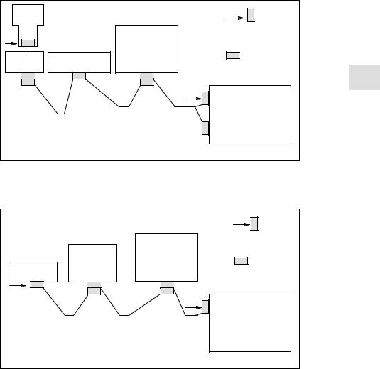
Fig. 3-1 Network installation with two terminating resistors in
MPI: PG, control 840D
BTSS: HHU, control 840D
|
|
on |
|
|
Terminating resistor |
|
|
fitted in connector |
|
OP030 |
PCU |
|
on |
|
MSTT |
|
|
|
Terminating resistor |
|
on |
|
|
|
hard-wired |
|
|
|
on |
|
|
BTSS |
|
|
Control 840D |
Fig. 3-2 Network installation with two terminating resistors in BTSS:
MSTT, control 840D
3-20 |
♥ Siemens AG 2006 All Rights Reserved |
SINUMERIK 840D/810D Start-Up Guide (IADC) – 03/2006 Edition |
03/2006 |
3 Settings, MPI/BTSS |
|
3.1 MPI network rules for SINUMERIK 840D |
3.1.1 |
Communication equipment |
|
|
|
The components involved in MPI and BTSS communication are PLC, NCK, |
|
|
|
COM and PCU/HMI. They allow communication between the active nodes. |
|
|
|
Communication between passive nodes, e.g. GD circuit communication, is not |
|
|
|
discussed here. |
|
|
|
3 |
||
|
The aforementioned component perform the following tasks concerning MPI |
||
|
and BTSS communication: |
|
|
|
S |
PLC and NCK |
|
|
|
PLC and NCK are both servers that provide communication links to client |
|
|
|
components and execute jobs via these client components upon request. |
|
|
|
The number of possible communication links from the server to the clients |
|
|
|
and the number of parallel function jobs (Read variables, Write variables, |
|
|
|
etc.) are limited. |
|
|
S |
HMI |
|
|
|
An HMI component is a client that requests communication links from one or |
|
|
|
more servers and sends jobs to them. |
|
|
S |
COM |
|
|
|
The COM component is a router that allows communication between va- |
|
|
|
rious component via different communication links (MPI, BTSS and Dual |
|
|
|
Port RAM). |
|
HMI (client)
Machine control panel (passive GD circuit node)
1 |
6 |
|
|
BTSS bus |
(1.5 MBaud) |
SIMATIC |
HMI (client) |
|
programming device |
||
0 |
1 |
MPI bus (187 5 kBaud)
 Default bus addresses
|
SINUMERIK 840D |
|
|
|
COM (router) |
|
|
X101 |
|
DPR |
|
|
Router |
|
|
|
|
|
|
13 |
|
|
|
|
|
|
NCK |
|
|
3 |
(server) |
|
PLC (server) |
|
|
X122 |
2 |
|
|
|
|
|
|
|
Router |
|
|
|
|
X102 |
|
|
PROFIBUS DP (12 MBaud) |
|
|
Fig. 3-3 Default application for SINUMERIK 840D
♥ Siemens AG 2006 All Rights Reserved |
3-21 |
SINUMERIK 840D/810D Start-Up Guide (IADC) – 03/2006 Edition |

3 Settings, MPI/BTSS |
03/2006 |
3.1MPI network rules for SINUMERIK 840D
HMI communication: BTSS bus
3
HMI communication: MPI bus
Associated conditions for STEP 7
Logon IDs
Communication links
An HMI component logs on onto the NCK and PLC servers as a client via the COM module and is allocated communication resources by them as a result of logging on.
Jobs with a bus address/job ID for NCK are routed by the COM module directly to the NCK. Jobs with different bus addresses/job IDs are routed to the PLC. This response is implicit routing, and no special routing information is required in the COM module about other communication nodes on adjacent bus systems.
An HMI component logs onto the NCK server as a client indirectly via the COM module and directly at the server PLC is allocated communication resources by them as a result of logging on.
Jobs with a bus address/job ID for NCK are routed by the COM module directly to the NCK. Jobs with different bus addresses/job IDs are ignored by the COM module. This response is also implicit routing, and no special routing information is required in the COM module about other communication nodes on adjacent bus systems.
It is not possible to configure the entire communication setup illustrated in Fig. 3-3 in SIMATIC STEP7. Thus, STEP7 and any other engineering tools will
not provide all the possible communication links. In particular, the COM module that acts as the link between the MPI and BTSS buses cannot be configured.
When a connection is established, a client component logs onto the PLC with its logon ID. Typical logon IDs include programming device: “PG” and operator panel: “OP”. One communication link on the PLC is reserved for a component with the logon ID “PG” and one for the “OP” logon ID. For historical reasons, an HMI component with the logon ID: “PG” by default. For the “M to N” function, it logs on with the logon ID: “OP”.
The NCK, COM and PLC components allow the following maximum number of possible communication links:
Component |
Number |
|
|
|
|
NCK |
5 |
|
|
|
|
COM |
|
|
|
|
|
|
from BTSS bus to NCK |
3 |
|
|
|
|
from BTSS bus to PLC |
3 |
|
|
|
|
from MPI bus to NCK |
3 |
|
|
|
PLC 1) |
|
|
|
PLC 315-2DP (contained in: CCU3 and NCU*.3) |
4 |
|
|
|
|
PLC 314C-2DP (contained in NCU*.4) |
12 |
|
|
|
|
PLC 317-2DP (contained in NCU*.5) |
32 |
|
|
|
|
from MPI bus to PLC |
2) |
|
|
|
1) One communication link is reserved by default for connecting a programming device
(PG) e.g. for diagnostics with STEP7.
2) The number results from the maximum number of PLCs integrated into the NCU, minus the active PLC communication links on the BTSS bus.
3-22 |
♥ Siemens AG 2006 All Rights Reserved |
SINUMERIK 840D/810D Start-Up Guide (IADC) – 03/2006 Edition |

03/2006 |
3 Settings, MPI/BTSS |
|
3.1 MPI network rules for SINUMERIK 840D |
Each client component requires the following communication links for communication with the NCK and PLC servers:
Component |
Number |
|
|
|||
|
|
|
|
|
|
|
HMI Advanced or HMI Embedded |
|
|
|
|
||
|
|
|
|
|
|
|
|
To NCK |
1 |
|
|
|
|
3 |
||||||
|
|
|
|
|
||
|
To PLC |
1 |
|
|
||
|
|
|
|
|||
|
|
|
|
|
|
|
Shopmill/Shopturn on HMI Advanced or HMI Embedded |
|
|
|
|
||
|
|
|
|
|||
|
|
|
|
|
|
|
|
To NCK 1) |
+1 |
|
|
|
|
|
To PLC 1) |
+1 |
|
|
|
|
STEP 7 on HMI |
|
|
|
|
||
|
|
|
|
|
|
|
|
To PLC 1) |
+1 |
|
|
|
|
1) In addition to the HMI communication link |
|
|
|
|
||
|
|
|
|
|
|
|
|
|
|
|
|
|
|
Note
A Protool configuration does not need an additional communication link for
ProtoolPro with the “SINUMERIK” option.
Equipment |
The following tables illustrate the communication equipment required for the |
||
required |
individual components: NCK, PLC and COM |
|
|
Table 3-1 |
NCK equipment required |
|
|
Resource unit |
|
|
Machine data |
Max. number of HMI resource units 1) |
10 |
$MN_MM_NUM_MMC_UNITS |
|
1) HMI Embedded and HMI Advanced require 2 resource units per communication link.
Table 3-2 PLC equipment required
PLC 314
PLC 315-2AF00
PLC 315-2AF01
PLC 315-2AF03
PLC 314C-2DP
|
|
|
|
|
|
|
PLC 317-2DP |
Communication links |
|
|
|
|
|
|
|
max. possible number |
4 |
4 |
4 |
4 |
12 |
32 |
|
Reserved for programming device |
1 |
1 |
1 |
1 |
1 |
1 |
|
Available for HMI components |
3 |
3 |
3 |
3 |
11 |
31 |
|
Table 3-3 |
COM equipment required |
|
|
|
|
|
|
|
|
|
|
|
|
PLC |
|
|
|
|
|
|
|
|
NCK |
Links 1) |
|
|
|
|
|
|
|
BTSS bus: max. possible number |
|
|
|
|
3 |
3 |
|
MPI bus: max. possible number |
|
|
|
|
1) |
3 |
|
1) Note: The MPI links are not routed via the COM module. They go directly to the PLC.
♥ Siemens AG 2006 All Rights Reserved |
3-23 |
SINUMERIK 840D/810D Start-Up Guide (IADC) – 03/2006 Edition |

3 Settings, MPI/BTSS |
03/2006 |
3.2MPI network rules for SINUMERIK 810D
3.2 |
MPI network rules for SINUMERIK 810D |
|
|
|
Please take the following basic rules into account when undertaking network |
|
|
installations: |
|
|
|
3 |
|
1. The bus line must be terminated at both ends. To do this, activate the termi- |
|
nating resistor in the MPI connector of the first and last node, and deactivate |
|
the remaining terminating resistors.
Note
SOnly two resistors are permissible.
SWith HHU, bus terminating resistors are hard-wired into the device.
2.It is necessary to apply 5 V voltage to at least 1 terminator. This occurs automatically when the MPI connector with active terminating resistor is connected to a live device.
3.Spur lines (lead cables from the bus segment to the node) should be as short as possible.
Note
Any spur lines that are not assigned should be removed if possible.
4.Each MPI node must be connected before being activated. When disconnecting an MPI node, the connection must be deactivated before the connector can be pulled out.
5.You can either connect one HHU and one HT6, or two HHUs or HT6s per bus segment. It is not permissible to connect bus terminators to the distributor boxes of an HHU or HT6.
If necessary, an intermediate repeater can be used to connect more than one HHU/HT6 to a bus segment.
6.The following cable lengths for the standard MPI without repeater must not be exceeded:
MPI (187.5 kBaud): max. total cable length 1000 m
Note
Piggy-back connectors are not recommended for power connections.
3-24 |
♥ Siemens AG 2006 All Rights Reserved |
SINUMERIK 840D/810D Start-Up Guide (IADC) – 03/2006 Edition |
03/2006 |
3 Settings, MPI/BTSS |
|
3.2 MPI network rules for SINUMERIK 810D |
Example A
Example B
HHU |
|
on |
|
|
|
|
|
||
|
|
Terminating resistor |
|
|
on |
|
fitted in connector |
|
|
|
PCU |
|
||
|
|
|
||
Distributor |
MSTT |
on |
|
|
|
|
|||
box |
Terminating resistor |
3 |
||
|
||||
|
|
|||
|
|
hard-wired in device |
||
|
|
|
||
|
MPI |
on |
|
|
|
|
Control 810D |
|
Fig. 3-4 Network installation with two terminating resistors in MPI:
BHG, control 810D
|
|
on |
|
|
Terminating resistor |
|
|
fitted in connector |
OP030 |
PCU |
on |
|
||
|
|
|
MSTT |
|
Terminating resistor |
|
|
|
on |
|
hard-wired |
|
|
|
MPI |
|
on |
|
|
Control 810D |
Fig. 3-5 Network installation with two terminating resistors in MPI:
MSTT, control 810D
♥ Siemens AG 2006 All Rights Reserved |
3-25 |
SINUMERIK 840D/810D Start-Up Guide (IADC) – 03/2006 Edition |

3 Settings, MPI/BTSS |
03/2006 |
3.3MPI default configuration for SINUMERIK 840D
3.3MPI default configuration for SINUMERIK 840D
One or two machine control panels (interface for customer’s operating panels, PP 031) and/or HHU are connected by means of parameter settings in the PLC basic program (FB1). In this case, parameter settings using the STEP7 tool
3 |
“Communication Configuration” are no longer required. |
|
|
||
|
Reference material: /FB1/ |
P3 Pl, Function manual for basic machines, |
|
|
PLC basic program powerline |
Standard |
SINUMERIK 840D with one PCU and one machine control panel (MSTT) or |
|
application |
interface for customer’s operating panel on the BTSS. |
|
Requirement for |
At least firmware release V 03_01_01 for |
|
the hardware |
S MCP |
|
|
|
|
|
S interface for customer’s operating panel/PP 031 |
|
Bus addresses |
Every node on the MPI/BTSS bus must have a bus address (0...31). |
|
PCU |
|
|
|
|
|
Default bus addresses |
|
|
1 |
|
BTSS 1.5 MBaud |
|
|
|
|
|
|
|
6 |
|
|
SINUMERIK 840D |
|
|
X101 |
|
MSTT/interface for |
|
13 |
customer’s operating panel |
|
|
|
||
|
|
|
NCK |
|
|
3 |
|
|
0 |
|
|
PG/start-up |
X122 |
|
PLC |
tool |
2 |
|
|
|
|
|
|
|
MPI 187.5 kBaud |
|
|
Fig. 3-6 Default application for SINUMERIK 840D
3-26 |
♥ Siemens AG 2006 All Rights Reserved |
SINUMERIK 840D/810D Start-Up Guide (IADC) – 03/2006 Edition |

03/2006 |
3 Settings, MPI/BTSS |
|
3.3 MPI default configuration for SINUMERIK 840D |
Bus address and
GD circuit
Note
The parameter settings for the bus address (on the machine control panel) or the GD circuit parameters (on the HHU) in the PLC basic program are used for
the logical addressing of the components. The physical addressing on the 3 BTSS/MPI is always done via the GD circuits, however. Each machine control
panel, interface for customer’s operating panel, etc, must be addressed with a separate GD circuit.
In the control, the bus address in the associated GD circuit is converted via the PLC program.
On the machine control panel, the bus address, and thus the associated GD circuits, are set via the DIP-FIX switches.
On the MPI, the same GD circuits are set, however, for the machine control panel, interface for customer’s operating panel and PP031 components, even if the bus addresses are different. This should be noted if more than one machine control panel, etc, is used.
The following table illustrates the interaction.
Table 3-4 |
Interaction between bus address and GD circuit |
|
|
|
|
Bus addresses on the MPI |
GD circuit |
|
|
|
|
|
15, 14, 13 |
1 |
|
|
|
|
12, 11 |
2 |
|
|
|
|
10, 9 |
3 |
|
|
|
|
8, 7 |
4 |
|
|
|
|
6 |
8 |
|
|
|
|
5, 4 |
5 |
|
|
|
Example:
2 machine control panels (MSTTs) are to be connected to the MPI on a control. The first MSTT can be connected to bus address 15 (GD circuit 1) and the second to bus address 12 (GD circuit 2).
MPI interface and
GD circuit
Note
If the “Communication Configuration” STEP7 tool is to be used to establish PLC-PLC cross-communication on the MPI, for example, and if one or more MSTTs are connected to the MPI, then the GD circuits assigned must be unique. The “Communication Configuration” STEP 7 tool assigns the GD circuits, starting with GD circuit 1 in ascending order. If the MSTTs are connected to the BTSS, then this has no effect on the PLC–PLC communication on the MPI.
♥ Siemens AG 2006 All Rights Reserved |
3-27 |
SINUMERIK 840D/810D Start-Up Guide (IADC) – 03/2006 Edition |

3 Settings, MPI/BTSS |
03/2006 |
3.4MPI default configuration for SINUMERIK 810D
Example:
GD circuits 1 and 2 are assigned by “Communication Configuration” as a result of the PLC–PLC cross-communication. A first MSTT on the MPI can then be assigned to GD circuit 3 (bus address 9 or 10), and a second MSTT on the MPI to GD circuit 4 (bus address 7 or 8).
3
3.4MPI default configuration for SINUMERIK 810D
Standard |
SINUMERIK 810D with PCU and one machine control panel (MSTT) or inter- |
application |
face for customer’s operating panel |
Hardware |
At least firmware release V 03_01_01 for |
requirements |
S MCP |
|
|
|
S interface for customer’s operating panel |
STEP7 |
from version 2.x |
MPI baud rate |
All MPI bus nodes operate at 187.5 kbaud. |
Bus addresses |
Every node on the MPI bus must have a bus address (0...15). |
PCU |
PG/start-up tool |
|
|
|
1 |
0 |
|
Bus addresses |
MPI bus |
|
|
|
187.5 kbaud |
|
|
|
|
|
|
|
|
|
|
14 |
|
SINUMERIK 810D |
|
||
|
|
|
|
MSTT/interface for |
|
|
|
PLC |
customer’s operating panel |
|
|
2 |
|
|
|
|
|
|
|
|
X122 |
|
|
|
|
|
3 |
NCK |
|
|
|
|
|
|
Fig. 3-7 Standard application for SINUMERIK 810D
3-28 |
♥ Siemens AG 2006 All Rights Reserved |
SINUMERIK 840D/810D Start-Up Guide (IADC) – 03/2006 Edition |

03/2006 |
3 Settings, MPI/BTSS |
|
3.4 MPI default configuration for SINUMERIK 810D |
Communication parameters
Assigned inputs/ outputs in the PLC–CPU
Configuration via FB1
If the MSTT/interface for customer’s operating panel is set to MPI address 14 and with SDB210 from the basic program diskette, the communication starts when the PLC is restarted (LEDs stop flashing).
Note |
3 |
|
The STEP7 project manager (S7 TOP) does not display the SDB as standard. To display the SDB, select “All blocks with SDBs” in menu View/Set filters.
The following bytes in the PLC CPU are then assigned to the MSTT or interface for customer’s operating panel:
SInput byte 0–7
SOutput byte 0–7
Communication does not start
SStatus bytes for error detection output bytes 12–15 (evaluated by basic program)
Parameterization on FB1 (basic program) for the MCP is already preset for the standard application.
If communication does not commence after a PLC reset (LEDs flashing), the following points should be checked:
SThe firmware release of the MSTT/interface for customer’s operating panel must be at least V03_01_01.
Scan:
The firmware version is displayed on the left, central and right LED block of the machine control panel if the keys “Feed start” and “Feed hold” are pressed simultaneously while the machine control panel is powering up.
SMPI cable and connector wiring
SDIP switch S3 (default setting)
SDB 210 must not be loaded.
♥ Siemens AG 2006 All Rights Reserved |
3-29 |
SINUMERIK 840D/810D Start-Up Guide (IADC) – 03/2006 Edition |

3 Settings, MPI/BTSS |
03/2006 |
3.5Deviation from standard configuration
3.5Deviation from standard configuration
Required documentation
3
Example
Procedure
SIMATIC STEP7, version 2.1
The following additional publications are required:
Reference material: /BH/ Device Manual, Operating Components /FB/ P3, PLC basic program
/S7HT/ Manual, Application of Tools
A configuration may be non-standard owing to one of the following:
SChange of address assignment
for the input, output or status bytes, or for the flag area or data block
SAdditional connection of a handheld unit (HHU)
SConnection of a 2nd MSTT or handheld terminal (HT 6)
In such cases, you must adjust the communications parameters and possibly the switch settings (addresses) of the bus nodes.
A new configuration is entered via the Define global data soft key. The following description of how to proceed is based on the assumption that you already know how to use this menu.
1.Set up new project and CPU programs using the STEP7 tool. A separate CPU program should be set up for each component of the plant (PLC, MSTT, HHU, 2.MSTT, HT 6, ...).
2.Connect the MPI nodes, i.e. network CPU programs with MPI address.
3.Activate the “Global Data” menu command in the following soft key sequence File Manager/MPI Network/Extras/Global Data and enter the desired configuration.
4.Compile this configuration. A new SDB is generated for each CPU program.
5.Set the cyclical transmission grid. Once the configuration has been compiled successfully for the first time, the “Conversion factor” and “Status” can be activated and then input.
6.Now compile your configuration again.
7.Transfer the SDB (from the CPU program of the PLC) to the PLC.
8.You must parameterize call FB1, DB7 in OB 100 in the basic PLC program for all operator control components (MPI nodes).
9.You must configure the status pointer (double word) for every component in FB1 for monitoring purposes.
Note
For a description of the “Global data” menu and the application, see
Reference material: /S7HT/ SIMATIC Step7 Manual, Starting up MPI bus nodes
3-30 |
♥ Siemens AG 2006 All Rights Reserved |
SINUMERIK 840D/810D Start-Up Guide (IADC) – 03/2006 Edition |
 Loading...