


Switchgear Type 8DH10
up to 24 kV, Gas-Insulated, Extendable
Medium-Voltage Switchgear
Catalog HA 41.11 · 2008
Answers for energy.

Contents |
Application, Requirements |
|
|
Features |
|
|
|
|
Application, Requirements |
Page |
|
|
|
|
Features, typical uses |
2 and 3 |
|
Technical Data |
|
|
|
|
|
Electrical data, filling pressure, |
|
|
temperature |
4 and 5 |
|
Switchgear installation, shipping data |
6 and 7 |
|
Product Range |
|
|
|
|
|
Product range overview |
8 to 15 |
|
Design |
|
|
|
|
|
Panel design |
16 and 17 |
|
Components |
|
|
|
|
|
3AH vacuum circuit-breaker |
18 and 19 |
|
Three-position switch-disconnector |
20 |
|
Busbars |
21 |
|
Transformers |
22 to 27 |
|
Cable connection |
28 |
|
Low-voltage equipment |
29 |
|
Dimensions |
|
|
|
|
|
Individual panels, panel blocks |
30 to 34 |
|
Metering panel combinations |
33 and 35 |
|
Floor openings and fixing points |
36 to 39 |
|
Cable connection examples |
40 |
|
Standards, Transport, Notes |
|
|
|
|
|
Standards, specifications, guidelines |
41 |
|
Transport data, classification |
42 |
|
Notes |
43 |
|
For further information, please refer to
•Catalog HA 40.1: (Switchgear Type 8DJ and 8DH, General Part)
•Supplements to Catalogs HA 45.31/41.11
The products and systems described in this catalog are manufactured and sold according to certified quality and enviromental management system (acc. ISO 9001 and ISO 14001).
(DQS Certificate Reg. No. DQS 003473 QM UM). The certificate is accepted in all IQNet countries.
8DH10 switchgear is a factoryassembled, type-tested, three-pole, metal-enclosed, metal-clad singlebusbar switchgear for in-door installation:
•Up to 24 kV
•Feeder currents up to 630 A
•Busbar currents up to 1250 A
Typical uses
8DH10 switchgear is used – even under severe environmental conditions – for power distribution in secondary distribution systems, such as
Substations, customer transfer substations, distribution substations and switching substations of power supply and public utilities
Industrial plants, such as:
•Wind power stations
•High-rise buildings
•Airports
•Lignite open-cast mines
•Underground railway stations
•Sewage treatment plants
•Port facilities
•Traction power supply systems
•Automobile industry
•Petroleum industry
•Chemical industry
•Cement industry
•Unit-type heating power stations
•Textile, paper and food industry
•Emergency power supply installations
Modular design
•Individual panels and panel blocks can be freely combined and extended – without gas work on site
•Low-voltage compartments can be supplied in two overall heights and are wired to the panel by means of plug-in connections
Reliability
•Type and routine-tested
•Standardized and manufactured using numerically controlled machines
•More than 500,000 8DJ/8DH panels in operation worldwide for many years
Quality and environment
Quality and environmental management system acc. to DIN EN ISO 9001 and
DIN EN ISO 14001
Personal safety
•Safe-to-touch and hermetically sealed primary enclosure
•HV HRC fuses and cable sealing ends are only accessible when outgoing feeders are earthed
•Operation only possible when enclosure is closed
•Logical mechanical interlocking
•Capacitive voltage detecting system to verify safe isolation from supply
•Feeder earthing by means of make-proof earthing switches
Security of operation
•Hermetically sealed primary enclosure independent of environmental effects (such as pollution, humidity and small animals) – sealed for life:
–Welded switchgear vessel
–Welded-in bushings and operating mechanism
•Operating mechanism parts maintenance-free
(IEC 62271-1 / VDE 0671-1)
•Operating mechanisms of switching devices located outside the switchgear vessel (primary enclosure)
•Switchgear interlocking system with logical mechanical interlocks
•Mechanical switch-position indicators integrated in the mimic diagram
Cost-efficiency
Extremely low “life-cycle costs” throughout the entire product service life as a result of:
•Maintenance-free concept
•Climatic independence
•Minimum space requirements
•Maximum availability
Security of investment
Innovative developments, such as:
•Modular design
•Switchgear extension without gas work on site
•Maintenance-free 3AH vacuum circuit-breaker
•SIPROTEC protection device family
© Siemens AG 2008
2 Switchgear Type 8DH10, up to 24 kV, Gas-Insulated, Extendable Siemens HA 41.11 2008
Technology
•Maintenance-free
•Climate-independent
•Partition class: Class PM (metallic partition)
•Three-pole primary enclosure, metal-enclosed
•Insulating gas SF6
•Welded switchgear vessel without seals, made of stainless steel, with welded-in bushings for electrical connections and mechanical components
•Three-position switch-discon- nector with load-break and make-proof earthing function
•Cable connection for bushings with outside cone
•Connection with cable plugs
–In ring-main feeders and circuit-breaker feeders with bolted contact (M16)
–In transformer feeders with plug-in contact
• Option: Connection with conven-
tional cable sealing ends
–For thermoplastic-insulated cables via elbow adapter AKE 20 / 630 (make Siemens)
–For paper-insulated massimpregnated cables via commercially available adapter systems
•Easy installation
•Option: Pressure absorber system
– Maintenance-free
– For rated short-time withstand current Ik 20 kA
– For single and multi-panel combinations of 700 mm to 2000 mm width (for panel type ME1 with max. 1 adjacent panel)
– With 300 mm high pressure absorber duct below the switchgear and
– With 115 mm deep pressure absorber duct for pressure relief upwards
– With screwed-on cable compartment cover
– Possible for switchgear with standard cable compartment cover Option: Deeper cable compartment cover: 105 or 300 mm
– For overall height of switchgear, see page 6
– Option: Free-standing arrangement, for overall height of switchgear 2300 mm and with rear cover
For further information concerning the pressure absorber system, please refer to page 39
and to Catalog HA 40.1
Standards
See page 41
H-R A4 1- 10 e4 sp
Application
Typical uses
HR4A 0131 ea sp
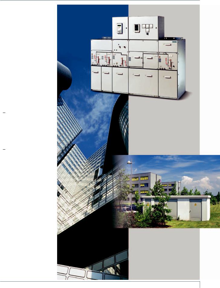
Example
Customer transfer switchgear
Application
Customer transfer substation in an accessible switchgear building (transformers, medium-voltage and low-voltage in a factory-assembled building)
Application
Power supply of high-rise buildings
HR4A 1- 10 e5 ps
Switchgear Type 8DH10, up to 24 kV, Gas-Insulated, Extendable Siemens HA 41.11 2008 3

Technical Data
Electrical data
|
|
Common |
|
Rated insulation level |
|
|
Rated voltage U |
|
kV |
7.2 |
|
|
|
|
12 |
|
|
15 |
|
|
17.5 B) |
24 |
|
|
|||||
|
|
|
|
|
|
|
r |
|
|
|
|
|
|
|
|
|
|
|
|
|
|
|
|
|
|
|
|
|
|
|
|
electrical data |
|
|
|
|
Rated short-dur. power-freq. withstand voltage Ud: |
|
|
|
|
|
|
|
|
|
|
|
|
|
|
|
|
|
|
|
|
||
|
|
|
|
|
|
|
|
|
|
|
|
28 1) |
|
|
|
|
|
|
|
38 B) |
|
|
|
|
|||||
|
|
|
|
|
|
|
– phase-to-phase, phase-to-earth, open contact gap kV |
20 |
|
|
|
|
|
|
36 |
|
|
|
50 |
|
|
||||||||
|
|
|
|
|
|
|
– across the isolating distance |
kV |
23 |
|
|
|
|
32 1) |
|
|
39 |
|
|
45 |
|
|
60 |
|
|
||||
|
|
|
|
|
|
|
Rated lightning impulse withstand voltage Up: |
|
|
|
|
|
75 1) |
|
|
|
|
|
|
|
|
|
|
|
|
|
|
||
|
|
|
|
|
|
|
– phase-to-phase, phase-to-earth, open contact gap kV |
60 |
|
|
|
|
|
|
95 |
|
|
95 |
|
|
125 |
|
|
||||||
|
|
|
|
|
|
|
– across the isolating distance |
kV |
70 |
|
|
|
|
85 1) |
|
|
110 |
|
110 |
|
|
145 |
|
|
|||||
|
|
|
|
Rated frequency fr |
|
|
|
|
|
50/60 Hz |
|
|
|
|
|
|
|
|
|
|
|
|
|
|
|
|
|||
|
|
|
|
|
|
|
|
|
|
|
|
|
|
|
|
|
|
|
|
|
|
|
|
|
|||||
|
|
|
|
Rated normal current I |
2) |
|
for busbar (standard) |
|
up to A |
630 |
|
|
|
|
630 |
|
|
630 |
|
630 |
|
|
630 |
|
|
||||
|
|
|
|
r |
|
|
|
|
|
|
|
|
|
|
|
|
|
|
|
|
|
|
|
|
|
|
|
|
|
|
|
|
|
|
|
|
for busbar (option) *) |
|
A |
1250 |
|
|
1250 |
|
1250 |
|
1250 |
|
1250 |
|
|
||||||||
|
|
Filling pressure, |
|
Rated filling level pre |
|
|
for insulation |
|
|
150 kPa |
(absolute) at |
20 °C |
|
|
|
|
|
|
|
|
|||||||||
|
|
|
|
|
|
|
|
|
|
|
|
|
|
||||||||||||||||
|
|
temperature, |
|
Min. functional level pme |
|
|
|
|
|
|
|
|
|
|
|
|
|
|
|
|
|
|
|
|
|
|
|
|
|
|
|
|
|
for insulation |
|
|
130 kPa |
(absolute) at |
20 °C |
|
|
|
|
|
|
|
|
||||||||||||
|
|
partition class |
|
Ambient air temperature T 3) |
|
Panels without secondary equipment |
Class |
“Minus 25 |
indoor” (-25 |
to +70 °C 4)) |
|
|
|
|
|
|
|||||||||||||
|
|
and |
|
|
|
|
|
|
|
|
|||||||||||||||||||
|
|
|
|
|
|
Panels with secondary equipment, |
Class |
“Minus 5 |
indoor” (-5 to |
+55 °C 4)) |
|
|
|
|
|
|
|
||||||||||||
|
|
classification |
|
|
|
|
|
|
|
|
|
|
|
||||||||||||||||
|
|
|
|
|
|
circuit-breaker panels |
|
|
|
|
|
|
|
|
|
|
|
|
|
|
|
|
|
|
|
|
|
|
|
|
|
|
|
|
|
|
|
|
|
|
|
|
|
|
|
|
|
|
|
|
|
|
|
|
|
|
|
|
|
|
|
|
|
Partition class |
|
|
|
|
Class |
PM (metallic |
partition) |
|
|
|
|
|
|
|
|
|
|
|
|
||||||
|
|
|
|
|
|
|
|
|
|
|
|
|
|
|
|
|
|
|
|
|
|
|
|
|
|
|
|
||
|
|
|
|
Loss of service |
|
|
LSC (loss of service continuity) |
|
LSC 2 |
|
|
|
|
|
|
|
|
|
|
|
|
|
|
|
|
|
|||
|
|
|
|
|
|
|
|
|
|
|
|
|
|
|
|
|
|
|
|
|
|
|
|||||||
|
|
|
|
continuity category 5) |
|
|
|
|
|
|
|
|
|
|
|
|
|
|
|
|
|
|
|
|
|
|
|
|
|
|
|
|
|
|
|
|
|
|
|
|
|
|
|
|
|
|
|
|
|
|
|
|
|
|
|
|
|
|
|
|
|
Panel data |
|
|
|
|
|
|
|
|
|
|
|
|
|
|
|
|
|
|
|
|
|
|
|
|
|
|
|
|
|
|
|
|
|
|
|
|
|
|
|
|
|
|
|
|
|
|
|
|
|
|
|
|
|||||
|
|
Ring-main panel |
|
Rated normal current I |
2) |
|
for feeder (for panel types RK ... and K ...) |
A |
400, 630 |
|
400, 630 |
400, 630 |
400, 630 |
400, 630 |
|
|
|||||||||||||
|
|
|
|
r |
|
|
|
|
|
|
|
|
|
|
|
|
|
|
|
|
|
|
|
|
|
|
|
|
|
|
|
type RK, |
|
|
|
|
for bus sectionalizer panel type LT2 |
A |
400, 630 |
|
400, 630 |
400, 630 |
400, 630 |
400, 630 |
|
|
|||||||||||||
|
|
bus sectionalizer |
|
|
|
|
|
|
|
||||||||||||||||||||
|
|
|
Rated short-time |
|
|
for switchgear with t |
= 1 s |
up to kA |
20 |
|
|
25 |
|
20 |
|
25 |
20 |
|
25 |
20 |
|
25 |
20 |
|
|
||||
|
|
|
|
|
|
|
|
|
|
|
|
|
|||||||||||||||||
|
|
panel type LT2, |
|
|
|
|
k |
|
|
|
|
|
|
|
|
|
|
|
|
|
|
|
|
|
|
|
|
|
|
|
|
|
withstand current Ik |
|
for switchgear with tk = 3 s (option) |
up to kA |
– |
|
|
– |
20 |
|
– |
20 |
|
– |
20 |
|
– |
20 |
|
|
|||||||
|
|
cable panel |
|
|
|
|
|
|
|
|
|
||||||||||||||||||
|
|
type K |
|
Rated peak withstand current Ip |
|
|
|
up to kA |
50 |
|
|
63 |
|
50 |
|
63 |
50 |
|
63 |
50 |
|
63 |
50 |
|
|
||||
|
|
|
|
Rated short-circuit making current Ima |
|
up to kA |
50 |
|
|
63 |
|
50 |
|
63 |
50 |
|
63 |
50 |
|
63 |
50 |
|
|
||||||
|
|
|
|
|
|
|
|
|
|
|
|
|
|
|
|
|
|
|
|
|
|
|
|
|
|
|
|
||
|
|
|
|
|
|
|
|
|
|
|
|
|
|
|
|
|
|
|
|
|
|
|
|
|
|
|
|
||
|
|
Transformer |
|
Rated normal current I |
2) |
|
for feeder 6) |
|
A |
200 |
|
|
|
|
200 |
|
|
200 |
|
200 |
|
|
200 |
|
|
||||
|
|
|
|
r |
|
|
|
|
|
|
|
|
|
|
|
|
|
|
|
|
|
|
|
|
|
|
|
|
|
|
|
panel type TR |
|
Rated short-time |
|
|
for switchgear with tk = 1 s |
up to kA |
20 |
|
|
25 |
|
20 |
|
25 |
20 |
|
25 |
20 |
|
25 |
20 |
|
|
||||
|
|
|
|
withstand current Ik |
|
|
|
|
|
|
|
|
|
|
|
|
|
|
|
|
|
|
|
|
|
|
|||
|
|
|
|
|
for switchgear with t |
= 3 s |
up to kA |
– |
|
|
– |
20 |
|
– |
20 |
|
– |
20 |
|
– |
20 |
|
|
||||||
|
|
|
|
|
|
|
k |
|
|
|
|
|
|
|
|
|
|
|
|
|
|
|
|
|
|
|
|
|
|
|
|
|
|
Rated peak withstand current I |
6) |
|
|
up to kA |
50 |
|
|
63 |
|
50 |
|
63 |
50 |
|
63 |
50 |
|
63 |
50 |
|
|
||||
|
|
|
|
|
p |
|
|
|
|
|
|
|
|
|
|
|
|
|
|
|
|
|
|
|
|
|
|
|
|
|
|
|
|
Rated short-circuit making current Ima 6) |
|
up to kA |
25 |
|
|
25 |
|
25 |
|
25 |
25 |
|
25 |
25 |
|
25 |
25 |
|
|
||||||
|
|
|
|
Reference dimension “e“ of the HV HRC fuse links |
|
mm |
292 7) |
|
|
292 |
|
|
442 |
|
442 |
|
|
442 |
|
|
|||||||||
|
|
|
|
|
|
|
|
|
|
|
|
|
|
|
|
|
|
|
|
|
|
|
|
||||||
|
|
|
|
|
|
|
|
|
|
|
|
|
|
|
|
|
|
|
|
|
|
|
|
||||||
|
|
Circuit-breaker |
|
Rated normal current I |
2) |
|
for feeder (for panel types LS ...) |
A |
400, 630 |
|
400, 630 |
400, 630 |
400, 630 |
400, 630 |
|
|
|||||||||||||
|
|
|
|
r |
|
|
|
|
|
|
|
|
|
|
|
|
|
|
|
|
|
|
|
|
|
|
|
|
|
|
|
panel type LS, |
|
|
|
|
for bus sectionalizer panel type LT1 |
A |
400, 630 |
|
400, 630 |
400, 630 |
400, 630 |
400, 630 |
|
|
|||||||||||||
|
|
bus sectionalizer |
|
Rated short-time |
|
|
for switchgear with t |
= 1 s |
up to kA |
20 |
|
|
25 |
|
20 |
|
25 |
20 |
|
25 |
20 |
|
25 |
20 |
|
|
|||
|
|
|
|
|
|
|
|
|
|
|
|
|
|||||||||||||||||
|
|
type LK/LT1 |
|
|
|
|
k |
|
|
|
|
|
|
|
|
|
|
|
|
|
|
|
|
|
|
|
|
|
|
|
|
|
withstand current Ik |
|
for switchgear with t |
= 3 s |
up to kA |
– |
|
– |
20 |
|
– |
20 |
|
– |
20 |
|
– |
20 |
|
|
|||||||
|
|
|
|
|
|
|
|
|
|
|
|||||||||||||||||||
|
|
|
|
|
|
|
k |
|
|
|
|
|
|
|
|
|
|
|
|
|
|
|
|
|
|
|
|
|
|
|
|
|
|
Rated peak withstand current Ip |
|
|
|
up to kA |
50 |
|
|
63 |
|
50 |
|
63 |
50 |
|
63 |
50 |
|
63 |
50 |
|
|
||||
|
|
|
|
Rated short-circuit making current Ima |
|
up to kA |
50 |
|
|
63 |
|
50 |
|
63 |
50 |
|
63 |
50 |
|
63 |
50 |
|
|
||||||
|
|
|
|
Rated short-circuit breaking current Isc 8) |
|
up to kA |
20 |
|
|
25 |
|
20 |
|
25 |
20 |
|
25 |
20 |
|
25 |
20 |
|
|
||||||
|
|
|
|
Electrical service life of |
|
|
at rated normal current |
|
10 000 operating cycles |
|
|
|
|
|
|
|
|
|
|
||||||||||
|
|
|
|
|
|
|
|
|
|
|
|
|
|
|
|
|
|||||||||||||
|
|
|
|
3AH vacuum circuit-breakers |
|
|
|
|
|
|
|
|
|
|
|
|
|
|
|
|
|
|
|
|
|
|
|
|
|
|
|
|
|
|
|
|
at rated short-circuit breaking current |
|
50 breaking operations |
|
|
|
|
|
|
|
|
||||||||||||
|
|
|
|
|
|
|
|
|
|
|
|
|
|
|
|
|
|
|
|
|
|
|
|
|
|
|
|
|
|
*) Not for billing metering panels type ME1
B) Data for Russian Federation:
–Rated voltage 12 kV
–Rated Short-duration powerfrequency withstand voltage 42 kV
1)According to some national requirements, higher values of the rated short-duration power-frequency withstand voltage available for
Ik = 20 kA with:
42 kV for phase-to-phase, phase-to-earth and open contact gap as well as
48 kV across the isolating distance
Higher values of the rated lighting impulse withstand voltage
(for Ik = 20 kA):
95 kV for phase-to-phase, phase-to-earth and open contact gap as well as
110 kV across the isolating distance
2)The rated normal currents apply to ambient air temperatures of max. 40 °C. The 24-hour mean value is max. 35 °C (according to IEC 62271-1 / VDE 0671-1)
3)Operating conditions according to IEC 62271-200.
For application, see also pages 2 and 41 (climate and ambient conditions)
4)Temperature range, reduced normal currents at ambient air temperatures > +40 °C
5)Classification according to
IEC 62271-200 (see also page 42)
6)Depending on the HV HRC fuse link, observe the max. let-through current of the HV HRC fuse links
7)Extension tube (150 mm long) required additionally for fuse mounting 442 mm
8)For the 3AH vacuum circuit-breaker
4 Switchgear Type 8DH10, up to 24 kV, Gas-Insulated, Extendable Siemens HA 41.11 2008

Technical Data
Electrical data
|
|
Common |
|
Rated insulation level |
|
Rated voltage U |
kV |
|
7.2 |
|
|
|
12 |
|
|
15 |
|
|
17.5 B) |
24 |
|
|
||||||
|
|
|
|
|
|
r |
|
|
|
|
|
|
|
|
|
|
|
|
|
|
|
|
|
|
|
|
|
|
|
|
electrical data |
|
|
|
Rated short-dur. power-freq. withstand voltage Ud: |
|
|
|
|
|
|
|
|
|
|
|
|
|
|
|
|
|
|
|
|
|
|
|
|
|
|
|
|
|
|
|
|
|
28 1) |
|
|
|
|
|
38 B) |
|
|
|
|
|||||||
|
|
|
|
|
|
– phase-to-phase, phase-to-earth, open contact gap kV |
|
20 |
|
|
|
|
36 |
|
|
|
50 |
|
|
|||||||||
|
|
|
|
|
|
– across the isolating distance |
kV |
|
23 |
|
|
|
32 1) |
|
39 |
|
|
45 |
|
|
|
60 |
|
|
||||
|
|
|
|
|
|
Rated lightning impulse withstand voltage Up: |
|
|
|
|
|
75 1) |
|
|
|
|
|
|
|
|
|
|
|
|
|
|
||
|
|
|
|
|
|
– phase-to-phase, phase-to-earth, open contact gap kV |
|
60 |
|
|
|
|
95 |
|
|
95 |
|
|
|
125 |
|
|
||||||
|
|
|
|
|
|
– across the isolating distance |
kV |
|
70 |
|
|
|
85 1) |
|
110 |
|
|
110 |
|
|
|
145 |
|
|
||||
|
|
|
|
Rated frequency fr |
|
|
|
|
50/60 Hz |
|
|
|
|
|
|
|
|
|
|
|
|
|
|
|
|
|
||
|
|
|
|
|
|
|
|
|
|
|
|
|
|
|
|
|
|
|
|
|
|
|
|
|
||||
|
|
|
|
Rated normal current I |
2) |
for busbar (standard) |
up to A |
|
630 |
|
|
|
630 |
|
|
630 |
|
|
630 |
|
|
|
630 |
|
|
|||
|
|
|
|
r |
|
|
|
|
|
|
|
|
|
|
|
|
|
|
|
|
|
|
|
|
|
|
|
|
|
|
|
|
|
|
for busbar (option) *) |
A |
|
1250 |
|
|
1250 |
|
1250 |
|
1250 |
|
1250 |
|
|
||||||||
|
|
Filling pressure, |
|
Rated filling level pre |
|
for insulation |
|
|
150 kPa |
|
(absolute) at |
20 °C |
|
|
|
|
|
|
|
|
|
|
|
|||||
|
|
|
|
|
|
|
|
|
|
|
|
|
|
|
|
|
|
|||||||||||
|
|
temperature, |
|
Min. functional level pme |
|
|
|
|
|
|
|
|
|
|
|
|
|
|
|
|
|
|
|
|
|
|
|
|
|
|
|
for insulation |
|
|
130 kPa |
|
(absolute) at |
20 °C |
|
|
|
|
|
|
|
|
|
|
|||||||||
|
|
partition class |
|
Ambient air temperature T 3) |
Panels without secondary equipment |
Class |
|
“Minus 25 |
|
indoor” (-25 |
to +70 °C 4)) |
|
|
|
|
|
|
|
||||||||||
|
|
and |
|
|
|
|
|
|
|
|
|
|
||||||||||||||||
|
|
|
|
|
Panels with secondary equipment, |
Class |
|
“Minus 5 |
|
indoor” (-5 to |
+55 °C 4)) |
|
|
|
|
|
|
|
|
|
||||||||
|
|
classification |
|
|
|
|
|
|
|
|
|
|
|
|
|
|
||||||||||||
|
|
|
|
|
circuit-breaker panels |
|
|
|
|
|
|
|
|
|
|
|
|
|
|
|
|
|
|
|
|
|
|
|
|
|
|
|
|
|
|
|
|
|
|
|
|
|
|
|
|
|
|
|
|
|
|
|
|
|
|
|
|
|
|
|
|
Partition class |
|
|
Class |
|
PM (metallic |
|
partition) |
|
|
|
|
|
|
|
|
|
|
|
|
|
||||
|
|
|
|
|
|
|
|
|
|
|
|
|
|
|
|
|
|
|
|
|
||||||||
|
|
|
|
Loss of service |
|
LSC (loss of service continuity) |
|
|
LSC 2 |
|
|
|
|
|
|
|
|
|
|
|
|
|
|
|
|
|
|
|
|
|
|
|
|
|
|
|
|
|
|
|
|
|
|
|
|
|
|
|
|
|
|
|
|
||||
|
|
|
|
continuity category 5) |
|
|
|
|
|
|
|
|
|
|
|
|
|
|
|
|
|
|
|
|
|
|
|
|
|
|
|
|
|
|
|
|
|
|
|
|
|
|
|
|
|
|
|
|
|
|
|
|
|
|
|
|
|
|
|
Panel data |
|
|
|
|
|
|
|
|
|
|
|
|
|
|
|
|
|
|
|
|
|
|
|
|
|
|
|
|
Busbar earthing |
|
Rated short-time |
|
for switchgear with tk = 1 s |
up to kA |
|
20 |
|
25 |
|
20 |
|
25 |
20 |
|
25 |
20 |
|
|
25 |
20 |
|
|
|||
|
|
panel |
|
withstand current Ik |
|
for switchgear with tk = 3 s (option) |
up to kA |
|
– |
|
– |
|
20 |
|
– |
20 |
|
– |
20 |
|
|
– |
20 |
|
|
|||
|
|
type SE, |
|
Rated peak withstand current Ip |
|
up to kA |
|
50 |
|
63 |
|
50 |
|
63 |
50 |
|
63 |
50 |
|
|
63 |
50 |
|
|
||||
|
|
busbar voltage |
|
|
|
|
|
|
|
|
|
|
|
|||||||||||||||
|
|
|
Rated short-circuit making current Ima |
up to kA |
|
50 |
|
63 |
|
50 |
|
63 |
50 |
|
63 |
50 |
|
|
63 |
50 |
|
|
||||||
|
|
metering panel |
|
|
|
|
|
|
|
|
|
|
||||||||||||||||
|
|
|
|
|
|
|
|
|
|
|
||||||||||||||||||
|
|
type MS1V/ME3 |
|
|
|
|
|
|
|
|
|
|
|
|
|
|
|
|
|
|
|
|
|
|
|
|
|
|
|
|
|
|
|
|
|
|
|
|
|
|
|
|
|
|
|
|
|
|
|
|
|
|
|
|
|||
|
|
|
|
|
|
|
|
|
|
|
|
|
|
|
|
|
|
|
|
|
|
|
|
|
|
|||
|
|
Billing metering |
|
Rated normal current I |
2) |
for transfer |
up to A |
|
630 |
|
|
|
630 |
|
|
630 |
|
|
630 |
|
|
|
630 |
|
|
|||
|
|
|
|
r |
|
|
|
|
|
|
|
|
|
|
|
|
|
|
|
|
|
|
|
|
|
|
|
|
|
|
panels |
|
|
|
for feeder (T with cable panel as type ME1-K) |
up to A |
|
630 |
|
|
|
630 |
|
|
630 |
|
|
630 |
|
|
|
630 |
|
|
|||
|
|
types ME1 |
|
|
|
for busbar metering |
up to A |
|
630 |
|
|
|
630 |
|
|
630 |
|
|
630 |
|
|
|
630 |
|
|
|||
|
|
and ME2 |
|
|
|
|
|
|
|
|
|
|
|
|
|
|
|
|
||||||||||
|
|
|
Rated short-time |
|
for switchgear with tk = 1 s |
up to kA |
|
– |
|
25 |
|
20 |
|
25 |
20 |
|
25 |
20 |
|
|
25 |
20 |
|
|
||||
|
|
|
|
|
|
|
|
|
|
|
|
|
|
|||||||||||||||
|
|
|
|
withstand current Ik |
|
for switchgear with t = 3 s |
up to kA |
|
20 |
|
– |
|
20 |
|
– |
20 |
|
– |
20 |
|
|
– |
20 |
|
|
|||
|
|
|
|
|
|
k |
|
|
|
|
|
|
|
|
|
|
|
|
|
|
|
|
|
|
|
|
|
|
|
|
|
|
Rated peak withstand current Ip |
|
up to kA |
|
50 |
|
63 |
|
50 |
|
63 |
50 |
|
63 |
50 |
|
|
63 |
50 |
|
|
||||
|
|
|
|
|
|
|
|
|
|
|
|
|
|
|
|
|
|
|
|
|
|
|
|
|
|
|
|
|
|
|
|
|
|
|
|
|
|
|
|
|
|
|
|
|
|
|
|
|
|
|
|
|
|
|
|
|
|
*) Not for billing metering panels type ME1
B) Data for Russian Federation:
–Rated voltage 12 kV
–Rated Short-duration powerfrequency withstand voltage 42 kV
1)According to some national requirements, higher values of the rated short-duration power-frequency withstand voltage available for
Ik = 20 kA with:
42 kV for phase-to-phase, phase-to-earth and open contact gap as well as
48 kV across the isolating distance
Higher values of the rated lighting impulse withstand voltage
(for Ik = 20 kA):
95 kV for phase-to-phase, phase-to-earth and open contact gap as well as
110 kV across the isolating distance
2)The rated normal currents apply to ambient air temperatures of max. 40 °C. The 24-hour mean value is max. 35 °C (according to IEC 62271-1 / VDE 0671-1)
3)Operating conditions according to IEC 62271-200.
For application, see also pages 2 and 41 (climate and ambient conditions)
4)Temperature range, reduced normal currents at ambient air temperatures > +40 °C
5)Classification according to
IEC 62271-200 (see also page 42)
Switchgear Type 8DH10, up to 24 kV, Gas-Insulated, Extendable Siemens HA 41.11 2008 5
Technical Data
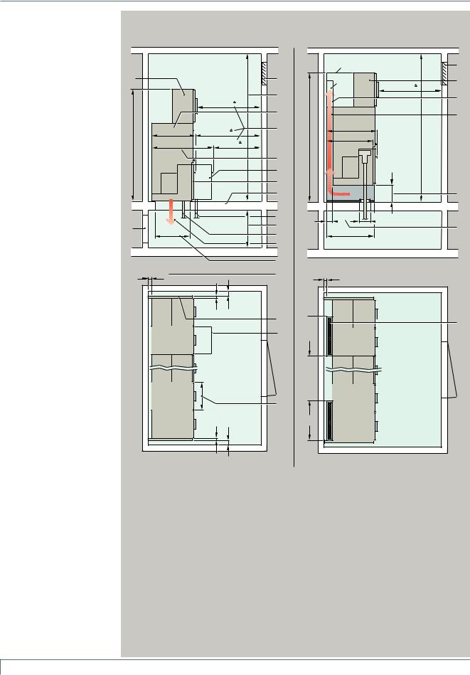
Switchgear installation
Room planning
Switchgear installation
Wall-standing arrangement
–Single row
–Double row (for face-to-face
arrangement) Option: Free-standing arrangement
For room planning and switchgear installation, please note:
–Floor openings: Dimensions see pages 36 to 39
–Direction of pressure relief acc. to serial no. 13
–Respective pressure relief rooms
Room dimensions see opposite dimension drawings
Door dimensions
The door dimensions depend on the
–Number of panels in a transport unit
–Design with or without low-voltage compartment
Switchgear fastening
•For floor openings and fixing points of the switchgear, see pages 36 to 39
•Foundations:
–Steel structure
–Steel-reinforced concrete
Panel dimensions see p. 30 to 34
Weight
For details, please refer to page 7.
*Switchgear height for version with pressure absorber duct:
–For wall-standing arrangement W 1950 mm (panel combination without metering panel ME1) W 2300 mm (for combination with metering panel ME1)
–For free-standing arrangement W 2300 mm (high end walls, rear wall and front covers, optional low-voltage compartment)
**Installation conditions for internal arc classification acc. to
IEC 62271-200
***Height of pressure absorber duct 2100 mm with:
–Wall-standing arrangement with metering panel ME1
–Free-standing arrangement for all panel types
BDepending on national specifications:
–For extension/panel replacement: Control aisle W 1000 mm recommended (for Germany
W 800 mm)
Switchgear installation with |
Switchgear installation with rear-side |
standard panels |
pressure absorber duct (option) |
|
Switchgear room |
|
|
|
|
22 |
|
|
|
2400** |
2 |
|
|
|
|
3 |
|
|
|
|
³1000 |
³ |
|
|
|
|
|
|
|
|
|
|
|
|
4 |
|
775 |
³1000 |
|
5 |
|
|
|
|
|||
2000 |
1070 |
|
³1000 |
|
|
|
|
|
|
|
|
|
|
|
|
|
6 |
|
|
|
|
|
7 |
|
|
|
|
|
8 |
|
|
|
|
|
9 |
1 |
|
|
|
>600 |
10 |
|
|
|
11 |
||
|
|
|
|
|
12 |
|
Cable basement |
|
|
|
13 |
|
Side view |
|
|
|
14 |
|
³15 |
|
|
|
18 |
|
|
10 |
³50 |
|
|
|
|
|
|
|
19 |
|
|
|
|
|
7 |
|
|
|
|
|
20 |
|
HA41-2286g eps |
10 |
³50 |
|
|
Top view
|
Switchgear room |
23 |
|
|
* |
|
|
|
*** |
|
22 |
|
|
³1000 |
|
|
|
|
|
|
|
|
13 |
|
|
|
15 |
|
890 |
|
** |
2300* |
828 |
|
³2400 |
|
|
||
|
|
300 |
16 |
|
|
|
|
|
115 |
~200 |
|
|
834 |
|
17 |
|
|
|
|
Cable basement
Side view
³15


 15 21
15 21
21
-HA41 eps2287h
Top view
1 |
Relief opening |
9 |
Foundation |
2 |
Opening (e.g. for ventilation |
10 |
2nd cable for connection with |
|
as option) |
|
of double T-plugs in conjunc- |
3 |
Room height |
|
tion with larger floor opening |
|
and design with deep cable |
||
|
|
|
|
4 |
Panel depth of the standard |
|
compartment cover |
|
panel (may be 15 mm deeper |
11 |
Height of the cable |
|
for free-standing arrangement, |
||
|
|
basement corresponding to |
|
|
depending on the panel design) |
|
|
|
|
the cable bending radius |
|
|
|
|
|
5 |
Control aisle B |
12 |
Cable |
|
|
||
6 |
Panel depth of panels with |
13 |
Direction of pressure relief |
|
deep cable compartment |
14 |
Floor openings: |
|
cover |
||
|
|
Dimensions see pages 34 to 37 |
|
|
|
|
|
7 |
Deep cable compartment |
15 |
Option: |
|
cover |
||
|
|
Pressure absorber duct |
|
|
|
|
|
8 |
Standard cable compartment |
16 |
Base height of the pressure |
|
|
cover |
absorber duct beneath the |
|
|
|
panel |
17Depth of the pressure absorber duct behind the panel
18Wall distance
19End wall
20Panel width
21Width of the pressure absorber duct
–700 mm for panel combinations
–Approx. 850 mm for metering panels type ME1
22Standard:
Low-voltage compartment for circuit-breaker panels
Option:
–Low-voltage compartment for all other panel types or
–Front cover
23Relief outlet
6 Switchgear Type 8DH10, up to 24 kV, Gas-Insulated, Extendable Siemens HA 41.11 2008
Technical Data
Shipping data
|
|
|
Individual panel, panel block |
|
Type |
|
|
Panel or panel combination |
|
Transport unit (including packing) for standard panels (without |
|
|
|
||||||||||||||||
|
|
|
or combinations thereof |
|
Short iden- |
|
|
|
|
|
|
|
pressure absorber system) |
|
|
|
|
|
|
|
|
|
|
||||||
|
|
|
for standard switchgear |
|
tification B |
|
|
|
|
|
|
|
|
|
|
|
|
|
|
|
|
|
|
|
|
|
|||
|
|
|
|
|
Width B1 |
|
Net weight 1) |
|
Width B2 |
Height |
Depth |
|
Volume |
|
Gross weight 1) |
|
|
|
|||||||||||
|
|
|
(without pressure relief duct) |
|
|
|
|
|
|
|
|
|
|
|
|
||||||||||||||
|
|
|
|
|
|
|
|
mm |
|
approx. kg |
|
m |
m |
T2 m |
|
m3 |
|
approx. kg |
|
|
|
||||||||
|
|
|
|
|
|
current |
in |
|
|
|
|
|
|
|
|
||||||||||||||
|
|
|
|
|
|
|
|
|
|
|
|
|
|
|
|
|
|
|
|
|
|
|
|
|
|
|
|||
|
|
|
|
|
|
|
|
future |
|
|
|
without / with |
|
|
without /with |
|
|
without /with |
without /with |
|
|
|
|||||||
|
|
|
|
|
|
|
|
|
|
|
LVC */ LVC* |
|
|
LVC */ LVC* |
|
|
LVC */ LVC* |
|
LVC */ LVC* |
|
|
|
|||||||
|
|
|
|
|
|
|
|
|
|
|
|
|
|
|
|
|
|
|
|
||||||||||
|
|
|
|
|
|
|
|
|
|
|
|
|
|
|
|
|
|
|
|
|
|
|
|
|
|
|
|
|
|
|
|
|
Transport of individual panels |
|
|
|
|
|
|
|
|
|
|
|
|
|
|
|
|
|
|
|
|
|
|
|
|
||
|
|
|
|
|
|
|
|
|
|
|
|
|
|
|
|
|
|
|
|
|
|
|
|
|
|
|
|||
|
|
|
Ring-main panel (standard) |
|
RK |
RK |
|
350 |
|
150 |
/ 210 |
|
|
0.70 |
1.60 / 2.20 |
1.10 |
|
1.23 / 1.69 |
|
210 |
/ 270 |
|
|
|
|||||
|
|
|
|
|
|
RK1 |
RK1 |
|
500 |
|
180 |
/ 240 |
|
|
0.70 |
1.60 / 2.20 |
1.10 |
|
1.23 / 1.69 |
|
240 |
/ 300 |
|
|
|
||||
|
|
|
|
|
|
RK2 |
RK1V |
|
500 |
|
200 |
/ 260 |
|
|
0.70 |
1.60 / 2.20 |
1.10 |
|
1.23 / 1.69 |
|
260 |
/ 320 |
|
|
|
||||
|
|
|
Cable panel (standard) |
|
K |
K |
|
350 |
|
145 |
/ 205 |
|
|
0.70 |
1.60 / 2.20 |
1.10 |
|
1.23 / 1.69 |
|
205 |
/ 265 |
|
|
|
|||||
|
|
|
Transformer panel |
|
TR |
TR1 |
|
500 |
|
180 |
/ 240 |
|
|
0.70 |
1.60 / 2.20 |
1.10 |
|
1.23 / 1.69 |
|
240 |
/ 300 |
|
|
|
|||||
|
|
|
Circuit-breaker panel (standard) |
LS1 |
LS1 |
|
500 |
|
– / 260 |
|
0.70 |
|
– / 2.20 |
1.10 |
|
– / 1.69 |
|
|
– / 320 |
|
|
|
|||||||
|
|
|
|
|
|
LS2 |
LS1V |
|
500 |
|
– / 380 |
|
0.70 |
|
– / 2.20 |
1.10 |
|
– / 1.69 |
|
|
– / 440 |
|
|
|
|||||
|
|
|
Circuit-breaker panel BB |
|
LST1 |
LST1 |
|
500 |
|
280 |
/ 340 |
|
|
0.70 |
1.60 / 2.20 |
1.10 |
|
1.23 / 1.69 |
|
320 |
/ 380 |
|
|
|
|||||
|
|
|
Bus sectionalizer panel with circuit-breaker |
LT1 |
LK |
|
500 |
|
– / 280 |
|
0.70 |
|
– / 2.20 |
1.10 |
|
– / 1.69 |
|
|
– / 340 |
|
|
|
|||||||
|
|
|
|
|
|
LT1-V |
LKV |
|
500 |
|
– / 380 |
|
0.70 |
|
– / 2.20 |
1.10 |
|
– / 1.69 |
|
|
– / 440 |
|
|
|
|||||
|
|
|
Bus sectionalizer panel with switch-disconnector |
LT2 |
LT |
|
500 |
|
150 / 210 |
|
|
0.70 |
1.60 / 2.20 |
1.10 |
|
1.23 / 1.69 |
|
210 / 270 |
|
|
|
||||||||
|
|
|
Busbar earthing panel |
|
SE1 |
SE |
|
350 |
|
150 / 210 |
|
|
0.70 |
1.60 / 2.20 |
1.10 |
|
1.23 / 1.69 |
|
210 / 270 |
|
|
|
|||||||
|
|
|
|
|
withvoltagetransformer |
SE2 |
SE1V |
|
500 |
|
250 / 310 |
|
|
0.70 |
1.60 / 2.20 |
1.10 |
|
1.23 / 1.69 |
|
310 / 370 |
|
|
|
||||||
|
|
|
Busbar voltage metering panel |
ME3 |
MS1V |
|
500 |
|
250 / 310 |
|
|
0.70 |
1.60 / 2.20 |
1.10 |
|
1.23 / 1.69 |
|
310 / 370 |
|
|
|
||||||||
|
|
|
Billing metering |
with cast-resin |
ME1 |
ME1 |
|
850 |
|
250 / 310 |
|
|
1.08 |
1.60 / 2.20 |
1.10 |
|
1.90 / 2.61 |
|
310 / 370 |
|
|
|
|||||||
|
|
|
panels, |
insulated transformers |
|
|
|
|
|
|
|
|
|
|
|
|
|
|
|
|
|
|
|
|
|
|
|
|
|
|
|
|
air-insulated ** |
with combined |
ME2 |
ME2 |
|
600 |
|
390 / 450 |
|
|
1.08 |
1.60 / 2.20 |
1.10 |
|
1.90 / 2.61 |
|
450 / 510 |
|
|
|
|||||||
|
|
|
|
|
|
|
|
|
|
|
|
|
|
||||||||||||||||
|
|
|
|
|
transformers |
|
|
|
|
|
|
|
|
|
|
|
|
|
|
|
|
|
|
|
|
|
|
|
|
|
|
|
Transport of panel blocks |
|
|
|
|
|
|
|
|
|
|
|
|
|
|
|
|
|
|
|
|
|
|
|
|
|
|
|
|
|
|
|
|
|
|
|
|
|
|
|
|
|
|
|
|
|
|
|
|
|
|
|
|||||
|
|
|
Ring-main panel block |
|
R-B2 |
|
|
700 |
|
280 / 400 |
|
|
1.08 |
1.60 / 2.20 |
1.10 |
|
1.90 / 2.61 |
|
340 / 460 |
|
|
|
|||||||
|
|
|
|
|
|
R-B3 |
|
|
1050 |
|
400 / 580 |
|
|
1.40 |
1.60 / 2.20 |
1.10 |
|
2.46 / 3.40 |
|
470 / 650 |
|
|
|
||||||
|
|
|
Transformer panel block |
|
T-B2 |
|
|
1000 |
|
320 / 440 |
|
|
1.40 |
1.60 / 2.20 |
1.10 |
|
2.46 / 3.40 |
|
390 / 510 |
|
|
|
|||||||
|
|
|
|
|
|
T-B3 |
|
|
1500 |
|
480 / 660 |
|
|
2.03 |
1.60 / 2.20 |
1.10 |
|
3.57 / 4.91 |
|
560 / 740 |
|
|
|
||||||
|
|
|
Ring-main/transformer panel block |
RT-B2 |
|
|
700 |
|
300 / 420 |
|
|
1.08 |
1.60 / 2.20 |
1.10 |
|
1.90 / 2.61 |
|
360 / 480 |
|
|
|
||||||||
|
|
|
|
|
|
2RT-B3 |
|
|
1050 |
|
450 / 630 |
|
|
1.40 |
1.60 / 2.20 |
1.10 |
|
2.46 / 3.40 |
|
520 / 700 |
|
|
|
||||||
|
|
|
|
|
|
3RT-B4 |
|
|
1400 |
|
580 / 820 |
|
|
2.03 |
1.60 / 2.20 |
1.10 |
|
3.57 / 4.91 |
|
660 / 900 |
|
|
|
||||||
|
|
|
Cable connection/transformer panel block |
KT-B2 |
|
|
700 |
|
300 / 420 |
|
|
1.08 |
1.60 / 2.20 |
1.10 |
|
1.90 / 2.61 |
|
360 / 480 |
|
|
|
||||||||
|
|
|
Transport of combinations of different individual panels or panel |
|
blocks |
|
|
|
|
|
|
|
|
|
|
|
|
|
|
|
|
|
|
||||||
|
|
|
|
|
|
|
|
|
|
|
|
|
|
|
|
|
|
|
|
|
|
|
|
|
|
|
|
||
|
|
|
Comprising |
|
|
|
|
|
Overall width B3 |
|
|
|
B2 |
|
|
|
T2 |
|
|
|
|
|
|
|
|
|
|||
|
|
|
– a number of individual panels or |
|
|
|
|
850 mm |
|
|
|
|
1.08 |
1.60 / 2.20 |
1.10 |
|
1.90 / 2.61 |
|
2) |
+ 60 *** |
|
|
|
||||||
|
|
|
– 1 panel block or |
|
|
|
|
|
|
|
|
|
|
|
|
|
|
||||||||||||
|
|
|
|
|
|
|
|
1200 mm |
|
|
|
|
1.40 |
1.60 / 2.20 |
1.10 |
|
2.46 / 3.39 |
|
2) |
+ 70 *** |
|
|
|
||||||
|
|
|
– a number of panel blocks or |
|
|
|
|
|
|
|
|
|
|
|
|
|
|||||||||||||
|
|
|
– individual panels with panel blocks |
|
|
|
|
1800 mm |
|
|
|
|
2.03 |
1.60 / 2.20 |
1.10 |
|
3.57 / 4.91 |
|
2) |
+ 85 *** |
|
|
|
||||||
|
|
|
|
|
|
|
|
|
|
2350 mm |
|
|
|
|
2.53 |
1.60 / 2.20 |
1.10 |
|
4.49 / 6.17 |
|
2) |
+ 100 *** |
|
|
|
||||
B Short identifications of the panels have been harmonized
BB Panel type LST1: Please refer to separate Catalog HA 45.31/41.11, Supplements to Catalogs HA 45.31/41.11
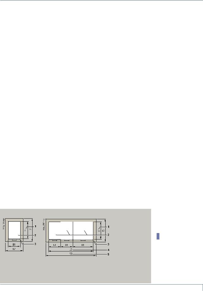
Transport units for shipping (top view)
With individual panel
or panel block
With combinations of different individual panels and/or panel blocks
(option: Panels bolted together and busbars mounted)
1T1 = Depth of individual panel or of panel block
2Individual panel or panel block, dimension B1 x T1
3Transport unit, dimension B2 x T2
4B3 = Overall width of combination of different individual panels
or panel blocks
5B2 = Width of the transport unit
1)The net weight and the gross weight depend on the extent to which they are equipped (e.g. with current transformers, motor operating mechanism, deep cable compartment cover) and are therefore given as mean value
Sum of the net weights of individual panels and / or panel blocks
*Low-voltage compartment, 600 mm high, weight approx. 60 kg depending on the panel type and on the extent
to which it is equipped
**The weights depend on the weights of the mounted transformers
***Packing weight
Switchgear Type 8DH10, up to 24 kV, Gas-Insulated, Extendable Siemens HA 41.11 2008 7
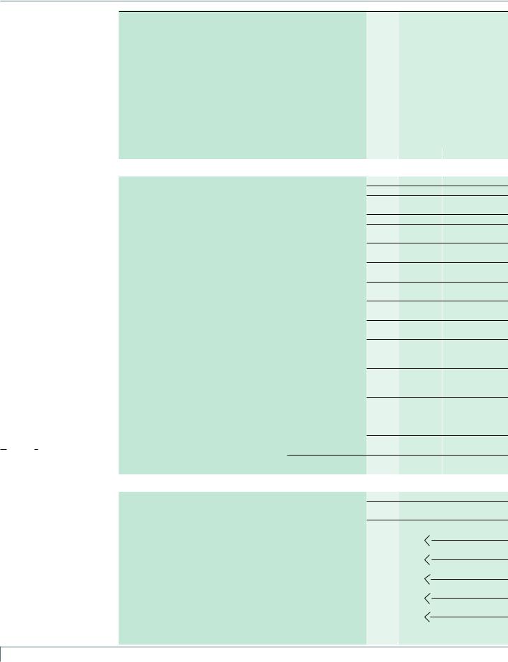
Product Range
Product range overview
Legend for pages 8 and 9
*Short identifications of the panels have been harmonized
**LV terminals as an option in the LV compartment (compartment to be ordered as an option)
B Three-position switch as three-position switch-disconnector (switch-disconnector CLOSED-OPEN-EARTHED)
BBThree-position switch as three-position circuit-breaker (disconnecting circuit-breaker CLOSED-OPEN-EARTHED), see Supplements to Catalogs
HA 45.31/41.11-2007
1)The equipment applies to the entire panel block, but it is located in the first feeder panel from the left
2)Low-voltage terminals arranged in the low-voltage niche of the ring-main or cable feeder
Designation of the |
Panel |
Type |
individual panels |
width |
|
and panel blocks |
|
|
|
|
|
Short identifications * |
||
|
|
|
current |
|
in future |
Individual panels |
|
|
Column no. |
|
|
|
|
|
|
||
|
|
|
|
|
|
Ring-main panel |
|
350 |
RK |
|
RK |
|
|
500 |
RK1 |
|
RK1 |
|
|
500 |
RK2 |
|
RK1V |
|
|
350 |
RK-U |
|
RK-U |
|
|
500 |
RK1-U |
|
RK1-U |
|
|
500 |
RK2-U |
|
RK1V-U |
Cable panel without earthing switch |
|
350 |
K |
|
K |
|
|
350 |
K-U |
|
K-U |
Cable panel with make-proof earthing switch |
|
350 |
K |
|
K |
|
|
350 |
K-U |
|
K-U |
Transformer panel |
|
500 |
TR |
|
TR1 |
|
|
500 |
TR-U |
|
TR1-U |
Transformer panel with plug-in voltage transformers |
|
500 |
TR-V |
|
TR1-V |
|
|
500 |
TR/V |
|
TR1/V |
Circuit-breaker panel |
|
500 |
LS1 |
|
LS1 |
|
|
500 |
LS1-U |
|
LS1-U |
Circuit-breaker panel with plug-in busbar voltage transformers |
500 |
LS2 |
|
LS1V |
|
|
|
500 |
LS2-U |
|
LS1V-U |
Circuit-breaker panel (with disconnecting circuit-breaker) BB |
|
500 |
LST1 |
|
LST1 |
Bus sectionalizer (with vacuum circuit-breaker) |
|
500 |
LT1 |
|
LK |
|
|
500 |
LT1-V |
|
LKV |
Bus sectionalizer (with switch-disconnector) |
|
500 |
LT2 |
|
LT |
Busbar earthing panel |
|
350 |
SE1 |
|
SE |
|
|
500 |
SE2 |
|
SE1V |
Busbar voltage metering panel |
|
500 |
ME3 |
|
MS1V |
|
|
|
|
|
|
Billing metering panel |
|
850 |
ME1 |
|
ME1 |
|
|
850 |
ME1-K |
|
ME1-K |
Billing metering panel for |
busbar connection |
850 |
ME1-S |
|
ME1-S |
|
cable connection |
850 |
ME1-KS |
|
ME1-K |
Billing metering panel with combined transformers |
|
600 |
ME2 |
|
ME2 |
Panel blocks |
|
|
Column no. |
|
|
|
|
|
|
||
|
|
|
|
|
|
Ring-main panel block |
|
700 |
R-B2 |
|
|
|
|
1050 |
R-B3 |
|
|
Transformer panel block |
|
1000 |
T-B2 |
|
|
|
|
1500 |
T-B3 |
|
|
Ring-main/transformer panel block |
|
700 |
RT-B2 |
RK |
|
|
|
T |
|||
|
|
|
|
||
|
|
1050 |
2RT-B3 |
RK |
|
|
|
T |
|||
|
|
|
|
||
|
|
1400 |
3RT-B4 |
RK |
|
|
|
T |
|||
|
|
|
|
||
Cable connection/transformer panel block |
|
700 |
KT-B2 |
K |
|
(cable panel without make-proof earthing switch) |
|
T |
|||
|
|
|
|||
|
|
|
|
||
Cable connection/transformer panel block |
|
700 |
KT-B2 |
K |
|
(cable panel with make-proof earthing switch) |
|
T |
|||
|
|
|
|||
|
|
|
|
||
8 Switchgear Type 8DH10, up to 24 kV, Gas-Insulated, Extendable Siemens HA 41.11 2008

Product Range
Equipment features
•
–
Basic equipment |
|
|
|
|
|
|
|
|
|
|
|
|
|
|
|
|
|
|
|
|
|
|
|
|
|
|
|
|
|
|
|
|
|
|
|
|
|
|
box |
|
|
|
|
|
|
|
|
|
|
|
|
|
|
|
indication |
CLOSED/ |
|
|
2NC |
|
OPEN) and |
|
|
|
|
|
|
|
|
||||||||||||||||||||||||
|
|
|
|
|
|
|
|
|
|
|
|
|
|
|
|
|
|
|
|
|
|
|
|
|
|
|
|
|
|
|
|
|
|
|
|
|
|
|
|
|
|
|
|
|
|
|
|
|
|
|
|
|
|
|
|
|
|
|
|
|
|
|
|
|
|
|
|
|
|
|
|
|
|
|
|
|
|
|
|||||||||||||||
|
|
|
|
|
|
|
|
|
|
|
|
|
|
|
|
|
|
|
|
|
|
|
|
|
|
|
|
|
|
|
|
|
|
|
|
|
|
|
|
|
|
|
|
|
|
|
|
|
|
|
|
|
|
|
|
|
|
|
|
2NO |
|
|
and |
|
|
|
|
|
|
|
|
|
|
|
|
|
|
|
|
||||||||||||||
|
|
|
|
|
|
|
|
|
|
|
|
|
|
|
|
|
|
|
|
|
|
|
|
|
|
|
|
|
|
|
|
|
|
|
|
|
|
|
|
|
|
|
|
|
|
|
|
|
|
|
|
|
|
|
|
|
|
|
|
|
|
|
|
|
|
|
|
|
|
|
|
|
|
|
|
|
|
|
|
|
|
||||||||||||
|
|
|
|
|
|
|
|
|
|
|
|
) |
|
|
|
|
|
|
|
|
) |
|
|
|
|
|
|
|
|
|
|
|
|
mechanism |
|
|
|
|
|
|
|
|
|
|
|
|
|
|
|
|
|
|
|
|
|
|
|
|
|
-breaker |
+ |
|
|
|
|
|
|
B |
|
|
|
|
|
|
|
|
|
|
|
||||||||||||||
|
|
|
|
|
|
|
|
|
|
|
|
|
|
|
|
|
|
|
|
BB |
|
|
|
|
|
|
|
|
|
|
|
|
|
|
|
|
|
|
|
|
|
|
|
|
|
|
|
|
|
|
|
|
|
|
|
|
|
|
|
|
|
|
|
|
|
|
|
|
|
|
|
|
|
|
|
|
|
|
|
|
|
|
|
|
|
|
|
|
|
|
|||
Not available |
|
|
|
|
|
|
|
|
|
|
|
|
|
|
|
|
|
|
|
|
|
|
|
|
|
|
|
|
|
|
|
|
|
|
|
|
|
|
|
|
) and |
|
|
devices) |
|
|
|
-disconnector . |
|
|
|
|
|
|
|
|
|
) |
|
|
|
|
|
|
|
|
|
|
-breaker |
||||||||||||||||||||||||
|
|
|
|
|
|
|
|
|
|
|
|
|
|
|
|
|
|
|
|
|
|
|
|
|
|
|
|
|
|
|
|
|
|
|
|
|
|
|
|
|
|
|
|
|
|
|
|
|
switch |
|
|
|
|
|
|
) |
|
|
|
|
|||||||||||||||||||||||||||||||||
|
|
|
|
|
|
|
|
|
|
|
|
B |
|
|
|
|
-breaker |
|
|
|
|
|
|
|
|
|
|
|
|
|
|
|
|
** |
|
|
|
|
|
|
|
|
|
|
|
|
|
|
|
-service |
|
|
|
|
|
|
circuit |
|
|
|
|
CLOSED |
|
|
|
|
|
|
|
|
|
|
|
|
|
||||||||||||||||||
|
|
|
|
|
|
|
|
|
|
|
|
|
|
|
|
|
|
|
|
|
|
|
|
operating |
|
|
|
|
|
|
|
|
|
|
) |
|
|
|
|
|
|
|
|
CLOSED/OPEN: |
|
|
|
|
|
|
|
|
|
|
|
|
|
|
|
|
|
|
|
||||||||||||||||||||||||||||||
|
|
|
|
|
|
|
|
|
|
|
|
|
|
|
|
|
|
|
|
|
|
|
|
|
|
|
|
|
|
|
|
|
|
|
|
|
|
|
|
|
|
|
|
|
|
|
|
|
|
|
|
|
|
|
-position |
|
|
|
|
|
|
|
|
|
|
|
|
|
|
|
|
|
|||||||||||||||||||||
|
|
|
|
|
|
|
|
|
|
|
|
|
|
|
|
|
|
|
|
|
|
|
|
|
|
|
|
|
|
|
|
|
|
|
|
|
|
|
|
|
|
|
|
|
|
BB |
|
|
|
|
|
|
|
|
|
|
|
|
|
|
2NC; |
|
|
|
|
|
|
|
|
|
|
|
|
|
|
|
|
|
|
|
|
|
|
|
|
|
|
|
|
|
|||
|
|
|
|
|
|
|
|
|
|
switch circuit |
|
|
|
|
on |
|
|
|
|
|
|
|
|
|
|
|
|
box |
|
|
|
|
|
|
B |
|
|
|
|
|
|
|
-for |
|
|
|
|
|
|
|
) |
(f |
|
|
|
|
|
|
|
|
|
|
|
|
|
|
|
|
BB |
) |
|
|
|
|
|||||||||||||||||||
|
|
|
|
|
|
|
|
|
|
|
|
|
|
|
|
|
|
|
mechanismcompartment . |
switching |
|
|
|
|
|
|
Switch |
|
|
+ |
|
|
|
|
|
|
BB |
|
|
|
|
|
|
|
|
|
|
|
|
switch |
|
|
|
|
|
BB |
|
|
|
circuit |
|||||||||||||||||||||||||||||||||
|
|
|
|
|
|
|
- |
|
- |
|
|
|
|
|
|
|
|
|
|
|
|
|
|
|
|
|
|
|
|
) |
|
|
|
|
|
|
|
) |
|
|
|
|
|
|
|
|
|
|
|
|
|
|
|
|
|
|
|
|
) |
|
|
|
|
||||||||||||||||||||||||||||||
|
|
|
|
|
|
|
|
|
|
|
|
|
|
|
place/screwed |
|
|
|
|
|
|
|
|
|
|
|
|
|
|
|
|
|
|
|
|
|
|
|
electrical |
ready |
: |
EARTHING |
|
|
|
|
|
|
|
|
|
|
|
|
|
|
|
|
|
|
|
|
) |
|
|
|
|
|
|
|
|
||||||||||||||||||||||
|
|
|
|
|
|
|
positionposition |
|
|
|
|
|
|
|
|
|
|
|
|
the |
|
|
|
|
|
|
|
|
|
|
switch |
|
|
|
|
|
|
BB |
|
|
|
|
2NO |
|
|
|
|
|
and |
|
three |
earthing |
|
|
|
|
|
and |
B and |
vacuum |
release |
||||||||||||||||||||||||||||||||
|
|
|
|
|
|
|
|
|
|
|
|
|
|
|
|
|
above |
|
|
|
|
|
|
|
|
|
|
|
|
|
|
|
|
|
|
|
|
|
|
|
|
|
|
B |
|
|
|
|
|
B |
|||||||||||||||||||||||||||||||||||||||||||
|
|
|
|
|
|
|
|
|
|
|
|
|
|
|
|
|
|
|
|
|
|
|
|
|
|
|
|
|
|
|
|
for |
|
|
|
|
|
and |
|
|
|
|
|
|
|
|
|
|
|
|
|
|
|
|
|
|
|
|
|
|
|
|
|
|
|
|
|
|
|
||||||||||||||||||||||||
|
|
|
|
|
|
|
|
|
|
|
|
|
|
|
|
|
|
|
|
|
|
|
|
|
|
|
|
|
|
|
|
|
|
|
|
|
|
|
|
|
|
|
|
|
|
|
|
|
|
|
|
|
|
|
|
|
|
|
|
|
|
|
|
|
|
|
|
|
|
|
|
|
|
|
|
||||||||||||||||||
|
|
|
|
|
|
|
|
|
|
|
|
|
|
|
|
|
|
|
|
|
|
|
|
|
|
|
|
|
|
|
|
|
|
|
|
|
|
|
.g |
|
|
|
|
B |
|
|
|
|
|
|
|
|
|
|
|
|
|
|
|
|
|
|
|
|
|
|
|
|
|
|
|
|
|
|
|
|
|
|
|||||||||||||||
|
|
|
|
|
|
|
|
|
|
|
|
|
|
|
|
|
|
|
|
|
|
. |
|
|
|
|
|
|
|
|
|
|
|
|
|
|
|
|
|
|
|
|
|
|
|
|
|
|
|
|
|
|
|
|
|
|
|
|
|
|
|
|
|
|
|
|
|
|
|
|
|
|
|
|
|
|
|
|
|
|
|
|
|
|
|||||||||
|
|
|
|
|
|
three three |
cover |
|
in |
|
|
|
|
|
comp |
operating |
|
|
|
|
|
-position (e |
|
|
|
|
|
|
CLOSED/OPEN:-pos |
switch |
between |
|
|
|
|
|
|
BB |
|
|
|
|
|
switch |
switch |
3AH |
|
operated) |
|||||||||||||||||||||||||||||||||||||||||||||
|
|
|
|
|
for |
|
for |
|
|
|
|
|
|
|
|
|
|
|
|
|
|
|
|
|
|
|
|
|
|
|
|
|
|
|
|
|
switch |
|
|
+ |
2NC, |
|
. |
|
|
|
|
|
|
|
|
|
|
-proof |
|
|
|
|
|
|
|
|
|
|
|
|
|
|
|
||||||||||||||||||||||||
|
|
|
|
|
|
|
|
|
|
|
|
|
|
|
|
|
|
|
|
|
terminal |
|
|
indicator |
|
|
remote |
|
|
|
) |
|
|
|
|
|
|
|
|
|
|
|
|
|
|
|
|
) |
|
|
|
|
|
|
|
|
|
indicator |
|
|
|
|
|
||||||||||||||||||||||||||||||
|
|
|
|
|
|
|
|
|
|
|
locked |
|
|
|
|
|
|
|
|
|
|
|
|
as |
|
|
|
for |
three |
|
|
|
|
|
2NO |
|
.three |
|
|
panel |
|
|
make |
|
|
and |
|
-position |
|
|
|
|
|
|
|
|
|
||||||||||||||||||||||||||||||||||||
|
|
|
mechanismmechanismcompartment |
|
|
|
|
|
|
|
terminal |
|
|
|
niche |
|
|
|
|
|
|
|
|
|
|
for |
|
|
EARTHING |
|
|
|
|
|
|
|
|
|
|
) |
|
|
|
|
|
|
|
-position |
|
|
|
|
-transformer |
|
** |
|
|||||||||||||||||||||||||||||||||||||
|
|
|
|
|
|
|
|
|
|
|
|
|
|
|
|
|
-service |
|
|
|
|
|
|
|
|
|
|
|
|
. |
|
|
-breaker |
|
|
|
|
|
|
for |
|
|
|
|
|
|
|
|
three |
|
-fault |
|
|
|
|
|
|||||||||||||||||||||||||||||||||||||
|
|
|
|
|
|
|
|
|
|
|
|
|
|
|
|
|
|
|
|
|
the |
|
release |
|
|
|
|
|
|
|
|
|
|
|
|
|
|
|
|
|
|
|
|
|
|
|
|
|
|
|
|
|
|
|
|
switch |
|
|
|
|
|
|
|
|
|
|
|
|
|
mechanism |
|
|
|
|
|||||||||||||||||||
|
|
|
|
|
|
|
|
|
|
|
|
|
|
as |
|
|
|
|
|
|
|
|
|
(1 |
|
|
|
|
|
|
|
|
|
|
|
|
|
|
|
|
|
|
|
|
|
|
-out |
|
|
|
|
|
|
|
|
|
|
|
|
|
|
|
|
|
|
|
|
||||||||||||||||||||||||||
|
|
|
|
|
|
|
|
|
|
|
|
|
|
|
|
|
|
|
|
|
|
|
|
|
|
|
|
|
|
|
-position |
|
|
|
|
|
|
|
|
|
|
|
|
|
|
|
|
|
|
|
|
|
|
|
|
|
|
|
|
|
|
compartmentcover |
|
|
|||||||||||||||||||||||||||||
|
|
|
|
|
|
|
|
cover |
|
|
|
|
|
terminals |
in |
|
|
|
|
|
|
|
|
|
|
|
|
NO) |
|
|
|
|
|
|
|
|
|
|
|
|
|
|
|
|
|
|
|
|
|
|
|
|
B |
|
|
three |
|
|
|
|
|
|
|
|
|
|
|
|
|
|
|
||||||||||||||||||||||
|
|
|
|
cable |
|
|
|
|
niche |
|
|
|
|
|
|
|
|
|
|
|
|
|
|
|
|
for |
|
|
+ |
|
|
|
|
|
|
|
|
|
|
|
circuit |
|
|
|
lock |
|
|
|
-out |
|
|
|
|
|
|
|
or |
|
|
|
|
|
|
|
|
|
|
|
|
||||||||||||||||||||||||
|
operatingoperating |
|
|
|
cable |
bracket |
|
|
|
|
|
|
|
|
as . |
|
-for |
|
|
|
|
|
|
three |
|
|
|
|
|
|
|
|
|
|
|
|
|
|
|
-breaker |
|
|
|
|
|
|
|
for |
|
for |
|
|
|
earth |
|
as |
|
|
|
|
|
|
|
|
clamps |
||||||||||||||||||||||||||||
|
|
|
|
|
|
|
|
|
|
|
|
|
|
|
|
|
|
|
|
|
|
|
|
|
|
|
|
|
|
CLOSED/OPEN: |
|
|
|
|
|
|
|
|
|
|
|
|
-positionlock |
|
|
device |
|
|
|
|
|
|
|
|
|
|
|
|
|
|
|
|
|
|
|||||||||||||||||||||||||||||
|
|
|
|
|
compartmentas |
|
|
|
|
|
|
|
|
|
|
-voltage |
|
|
|
|
|
|
|
switch |
|
|
|
|
|
|
2NC, |
|
|
|
.mechan |
|
circuit |
|
|
|
|
|
|
|
|
|
|
|
|
|
|
|
|
|
|
|
|
|
|
|
|
|
|
|
|
current |
|
|
cable equipment |
||||||||||||||||||||||||
|
|
|
|
|
|
|
|
|
|
|
|
|
|
|
low |
|
|
|
shunt |
ready |
|
|
|
|
|
2NO |
|
|
|
|
|
-operat |
|
|
|
|
|
|
|
|
|
|
|
|
|
|
|
|
|
|
|
|
|
-circuit |
|
operating |
|
|
|
||||||||||||||||||||||||||||||||||
|
|
|
for |
|
|
|
|
|
|
|
|
|
|
|
|
|
|
|
|
|
|
|
|
|
|
|
|
|
|
|
|
|
|
|
in |
|
|
|
|
|
|
|
|
|
|
|
|
|
|
|
|
|
|
|
|
|
|
|
|
|
|
-voltage-voltage |
|
|
|
|
|||||||||||||||||||||||||||
|
Manual Manual InterlockCable |
C |
|
-voltage-voltage |
|
|
|
|
|
|
|
|
|
|
|
|
|
|
.switch |
|
|
LST |
|
Motor |
|
Interlock |
|
|
|
-earthing |
|
|
Closing LockingShort |
Motor |
|
|
|
|
|
|
|
|
|
|
|
|
|||||||||||||||||||||||||||||||||||||||||||||||
|
|
Low |
|
Low |
SeparateRelease MechanSignallingAux OPEN:type |
|
|
|
|
|
|
|
De |
|
|
|
of |
|
|
|
|
Release Low |
|
Low |
MountedSecondary |
||||||||||||||||||||||||||||||||||||||||||||||||||||||||||||||||||||
|
|
|
|
|
-rail |
|
|
|
|
|
|
|
|
|
|
|
|
|
|
|
|
|
|
|
|
|
|
|
|
|
|
|
|
|
|
|
|
|
|
|
|
|
|
|
|
vacuum |
|
|
|
|
|
three |
|
|
|
|
|
|
|
|
|
|
|
|
|
|
|
|
|
|
|
|
|
|
|
|
|
|
|
|
|
|
|
|
|
||||||||
|
|
|
|
|
|
|
|
|
|
|
|
|
|
|
|
|
|
|
|
|
|
|
|
|
|
|
|
|
|
|
|
|
|
|
|
|
|
|
|
|
|
|
|
|
|
|
|
|
|
|
|
|
|
|
|
|
|
|
|
|
|
|
|
|
|
|
|
|
|
|
|
|
|
|
|
|
|
|
|
|
|
|
|
|
|
|
|
||||||
1 |
2 |
3 |
4 |
|
5 |
|
6 |
|
7 |
|
|
8 |
|
|
|
|
9 |
|
10 |
|
11 |
|
|
|
|
|
|
12 |
|
|
|
|
|
|
13 |
|
|
|
14 |
|
|
|
|
15 |
|
|
16 |
|
|
|
17 |
|
18 |
|
|
19 |
|
20 |
|
21 |
|
|
22 |
23 |
|
24 |
|
|
|||||||||||||||||||||||||
• – • – • • – – – • ° |
|
|
|
|
|
|
|
° |
|
|
|
|
|
|
|
° |
|
|
|
|
– |
|
|
|
|
|
– |
|
|
|
|
° ° ° |
|
|
|
– – |
|
|
° ° ° ° |
|
|
||||||||||||||||||||||||||||||||||||||||||||||||||||
• – • – • • – – – • ° |
|
|
|
|
|
|
|
° |
|
|
|
|
|
|
|
° |
|
|
|
|
– |
|
|
|
|
|
– |
|
|
|
|
° ° ° |
|
|
|
– – |
|
|
° ° ° ° |
|
|
||||||||||||||||||||||||||||||||||||||||||||||||||||
• – |
• – • • – – – • ° |
|
|
|
|
|
|
|
° |
|
|
|
|
|
|
|
° |
|
|
|
|
– |
|
|
|
|
|
– |
|
|
|
|
° ° ° |
|
|
|
– – |
|
|
° ° ° ° |
|
|
|||||||||||||||||||||||||||||||||||||||||||||||||||
|
|
|
|
|
|
|
|
|
|
|
|
|
|
|
|
|
|
|
|
|
|
|
|
|
|
|
|
|
|
|
|
|
|
|
|
|
|
|
|
|
|
|
|
||||||||||||||||||||||||||||||||||||||||||||||||||
• – • – – • – – – • ° |
|
|
|
|
|
|
|
° |
|
|
|
|
|
|
|
° |
|
|
|
|
– |
|
|
|
|
|
– |
|
|
|
|
° ° |
|
– – – |
|
|
° ° |
– |
|
° |
|
|
|||||||||||||||||||||||||||||||||||||||||||||||||||
• – • – – • – – – • ° |
|
|
|
|
|
|
|
° |
|
|
|
|
|
|
|
° |
|
|
|
|
– |
|
|
|
|
|
– |
|
|
|
|
° ° |
|
– – – |
|
|
° ° |
– |
|
° |
|
|
|||||||||||||||||||||||||||||||||||||||||||||||||||
• – • – – • – – – • ° |
|
|
|
|
|
|
|
° |
|
|
|
|
|
|
|
° |
|
|
|
|
– |
|
|
|
|
|
– |
|
|
|
|
° ° ° |
|
|
|
– – |
|
|
° ° |
– |
|
° |
|
|
|||||||||||||||||||||||||||||||||||||||||||||||||
– – – • • • – – – • ° |
|
|
|
|
|
|
|
– |
|
|
|
|
|
|
|
– |
|
|
|
|
– |
|
|
|
|
|
– |
|
|
|
|
– – |
|
|
° |
|
|
|
– – |
|
|
° ° ° ° |
|
|
|||||||||||||||||||||||||||||||||||||||||||||||||
– – – • – • – – – • ° |
|
|
|
|
|
|
|
– |
|
|
|
|
|
|
|
– |
|
|
|
|
– |
|
|
|
|
|
– |
|
|
|
|
– – – – – |
|
|
° ° |
– |
|
° |
|
|
|||||||||||||||||||||||||||||||||||||||||||||||||||||
• – • – • • – – – • ° |
|
|
|
|
|
|
|
° |
|
|
|
|
|
|
|
– |
|
|
|
|
– |
|
|
|
|
|
– |
|
|
|
|
– |
|
|
|
° ° |
|
|
|
– – |
|
|
° ° ° ° |
|
|
||||||||||||||||||||||||||||||||||||||||||||||||
• – • – – • – – – • ° |
|
|
|
|
|
|
|
° |
|
|
|
|
|
|
|
– |
|
|
|
|
– |
|
|
|
|
|
– |
|
|
|
|
– |
|
|
|
° |
|
– – – |
|
|
° ° |
– |
|
° |
|
|
|||||||||||||||||||||||||||||||||||||||||||||||
• – • – • – • – |
|
|
|
|
° • ° |
|
|
|
|
|
|
|
° |
|
|
|
|
|
|
|
° |
|
|
|
|
– |
|
|
|
|
|
° |
|
|
|
|
– |
|
|
|
° |
|
– – – |
|
|
° ° ° ° |
|
|
|||||||||||||||||||||||||||||||||||||||||||||
• – • – – – • – |
|
|
|
|
° • ° |
|
|
|
|
|
|
|
° |
|
|
|
|
|
|
|
° |
|
|
|
|
– |
|
|
|
|
|
° |
|
|
|
|
– |
|
|
|
° |
|
– – – |
|
|
° ° |
– |
|
° |
|
|
||||||||||||||||||||||||||||||||||||||||||
• – • – • – – – |
|
|
|
|
° • ° |
|
|
|
|
|
|
|
° |
|
|
|
|
|
|
|
° |
|
|
|
|
° |
|
|
|
|
|
– |
|
|
|
|
° ° ° ° ° • |
|
|
|
– |
° ° |
|
|
|||||||||||||||||||||||||||||||||||||||||||||||||
• – • – – – – – |
|
|
|
|
° • ° |
|
|
|
|
|
|
|
° |
|
|
|
|
|
|
|
° |
|
|
|
|
° |
|
|
|
|
|
– |
|
|
|
|
° ° |
|
– |
|
|
|
° ° • – – |
|
° |
|
|
||||||||||||||||||||||||||||||||||||||||||||||
• – • – • – – – |
|
|
|
|
° • ° |
|
|
|
|
|
|
|
° |
|
|
|
|
|
|
|
° |
|
|
|
|
° |
|
|
|
|
|
– |
|
|
|
|
° ° ° ° ° • – |
° ° |
|
|
|||||||||||||||||||||||||||||||||||||||||||||||||||||
• – • – – – – – |
|
|
|
|
° • ° |
|
|
|
|
|
|
|
° |
|
|
|
|
|
|
|
° |
|
|
|
|
° |
|
|
|
|
|
– |
|
|
|
|
° ° |
|
– |
|
|
|
° ° • – – |
|
° |
|
|
||||||||||||||||||||||||||||||||||||||||||||||
– • |
• – • |
|
• |
|
• – |
|
|
|
|
° • |
|
|
° |
|
|
|
|
|
|
|
• |
|
|
|
|
|
|
|
° |
|
|
|
|
– |
|
|
|
|
|
° |
|
|
|
|
° ° ° – |
|
|
° ° ° ° ° |
|
|
|||||||||||||||||||||||||||||||||||||||||||
• – – • – – – – |
|
|
|
|
° • ° |
|
|
|
|
|
|
|
° |
|
|
|
|
|
|
|
° |
|
|
|
|
° |
|
|
|
|
|
– |
|
|
|
|
– |
|
|
|
• |
|
– |
|
|
|
° ° • |
|
|
|
– – |
|
° |
|
|
||||||||||||||||||||||||||||||||||||||
• – – • – – – – |
|
|
|
|
° • ° |
|
|
|
|
|
|
|
° |
|
|
|
|
|
|
|
° |
|
|
|
|
° |
|
|
|
|
|
– |
|
|
|
|
– • – |
|
|
|
° ° • – – |
|
° |
|
|
||||||||||||||||||||||||||||||||||||||||||||||||
• – – • – • – – – • ° |
|
|
|
|
|
|
|
° |
|
|
|
|
|
|
|
° |
|
|
|
|
– |
|
|
|
|
|
– |
|
|
|
|
– • – – – |
|
|
° ° |
– |
|
° |
|
|
|||||||||||||||||||||||||||||||||||||||||||||||||||||
• – • – – • – – – • ° |
|
|
|
|
|
|
|
° |
|
|
|
|
|
|
|
– |
|
|
|
|
– |
|
|
|
|
|
– |
|
|
|
|
– • – – – |
|
|
° ° |
– |
|
° |
|
|
|||||||||||||||||||||||||||||||||||||||||||||||||||||
• – • – – • – – – • ° |
|
|
|
|
|
|
|
° |
|
|
|
|
|
|
|
– |
|
|
|
|
– |
|
|
|
|
|
– |
|
|
|
|
– • – – – |
|
|
° ° |
– |
|
° |
|
|
|||||||||||||||||||||||||||||||||||||||||||||||||||||
• – – • – • – – – • ° |
|
|
|
|
|
|
|
° |
|
|
|
|
|
|
|
° |
|
|
|
|
– |
|
|
|
|
|
– |
|
|
|
|
– ° – – – |
|
|
° ° |
– |
|
° |
|
|
|||||||||||||||||||||||||||||||||||||||||||||||||||||
– – – • – – – • – – – |
|
|
|
|
|
|
|
– |
|
|
|
|
|
|
|
– |
|
|
|
|
– |
|
|
|
|
|
– |
|
|
|
|
– – – – – |
|
|
° ° – ° |
|
|
||||||||||||||||||||||||||||||||||||||||||||||||||||||||
– – – • • – – • – – – |
|
|
|
|
|
|
|
– |
|
|
|
|
|
|
|
– |
|
|
|
|
– |
|
|
|
|
|
– |
|
|
|
|
– – – – – |
|
|
° ° ° ° |
|
|
||||||||||||||||||||||||||||||||||||||||||||||||||||||||
– – – • – – – • – – – |
|
|
|
|
|
|
|
– |
|
|
|
|
|
|
|
– |
|
|
|
|
– |
|
|
|
|
|
– |
|
|
|
|
– – – – – |
|
|
° ° |
– |
|
° |
|
|
|||||||||||||||||||||||||||||||||||||||||||||||||||||
– – – • • – – • – – – |
|
|
|
|
|
|
|
– |
|
|
|
|
|
|
|
– |
|
|
|
|
– |
|
|
|
|
|
– |
|
|
|
|
– – – – – |
|
|
° ° ° ° |
|
|
||||||||||||||||||||||||||||||||||||||||||||||||||||||||
– – – • – – – – – – – |
|
|
|
|
|
|
|
– |
|
|
|
|
|
|
|
– |
|
|
|
|
– |
|
|
|
|
|
– |
|
|
|
|
– – – – – |
|
|
° ° |
– |
|
° |
|
|
|||||||||||||||||||||||||||||||||||||||||||||||||||||
1 |
2 |
3 |
4 |
|
5 |
|
6 |
|
7 |
|
|
8 |
|
|
|
|
9 |
|
10 |
|
11 |
|
|
|
|
|
|
12 |
|
|
|
|
|
|
13 |
|
|
|
14 |
|
|
|
|
15 |
|
|
16 |
|
|
|
17 |
|
18 |
|
|
19 |
|
20 |
|
21 |
|
|
22 |
23 |
|
24 |
|
|
|||||||||||||||||||||||||
• – • – • • – – – •1) |
|
°1) |
|
|
|
|
|
|
° |
|
|
|
|
|
|
|
° |
|
|
|
|
– |
|
|
|
|
|
– |
|
|
|
|
– |
|
|
|
° ° |
|
|
|
– – |
|
|
° ° ° ° |
|
|
|||||||||||||||||||||||||||||||||||||||||||||||
• – • – • • – – – •1) |
|
°1) |
|
|
|
|
|
|
° |
|
|
|
|
|
|
|
° |
|
|
|
|
– |
|
|
|
|
|
– |
|
|
|
|
– |
|
|
|
° ° |
|
|
|
– – |
|
|
° ° ° ° |
|
|
|||||||||||||||||||||||||||||||||||||||||||||||
• – • – • – – – |
|
|
|
|
° •1) |
|
°1) |
|
|
|
|
|
|
° |
|
|
|
|
|
|
|
° |
|
|
|
|
– |
|
|
|
|
|
° |
|
|
|
|
– |
|
|
|
° |
|
– – – |
|
|
° ° ° ° |
|
|
||||||||||||||||||||||||||||||||||||||||||||
• – • – • – – – |
|
|
|
|
° •1) |
|
°1) |
|
|
|
|
|
|
° |
|
|
|
|
|
|
|
° |
|
|
|
|
– |
|
|
|
|
|
° |
|
|
|
|
– |
|
|
|
° |
|
– – – |
|
|
° ° ° ° |
|
|
||||||||||||||||||||||||||||||||||||||||||||
• – • – • • – – – •1) |
|
°1) |
|
|
|
|
|
|
° |
|
|
|
|
|
|
|
° |
|
|
|
|
– |
|
|
|
|
|
– |
|
|
|
|
° ° ° |
|
|
|
– – |
|
|
° ° ° ° |
|
|
|||||||||||||||||||||||||||||||||||||||||||||||||||
• – • – • |
|
|
|
– – |
|
|
|
|
° 1) |
|
|
1) |
|
|
|
|
|
|
|
° |
|
|
|
|
|
|
|
° |
|
|
|
|
– |
|
|
|
|
|
° |
|
|
|
|
– |
|
|
|
° |
|
– – – |
|
|
° ° ° ° |
|
|
||||||||||||||||||||||||||||||||||||||
– – – • • • – – – •1) |
|
°1) |
|
|
|
|
|
|
– |
|
|
|
|
|
|
|
– |
|
|
|
|
– |
|
|
|
|
|
– |
|
|
|
|
– – ° – – |
|
|
° ° ° ° |
|
|
|||||||||||||||||||||||||||||||||||||||||||||||||||||||
• – – – • |
|
2) |
|
– – |
|
|
|
|
° |
|
|
|
|
|
1) |
|
|
|
|
|
|
|
° |
|
|
|
|
|
|
|
° |
|
|
|
|
– |
|
|
|
|
|
° |
|
|
|
|
– |
|
|
|
° – – – |
|
|
° ° ° ° |
|
|
|||||||||||||||||||||||||||||||||||||
|
|
|
|
|
|
|
|
|
|
|
|
° |
|
|
|
|
|
|
|
|
|
|
|
|
|
|
|
|
|
|
|
|
|
|
|
|
|
|
|
|
|
|
|
|
|
|
|||||||||||||||||||||||||||||||||||||||||||||||
• – • – • • – – – •1) |
|
|
|
|
|
|
|
|
° |
|
|
|
|
|
|
|
– |
|
|
|
|
– |
|
|
|
|
|
– |
|
|
|
|
– |
|
|
|
° ° |
|
|
|
– – |
|
|
° ° ° ° |
|
|
|||||||||||||||||||||||||||||||||||||||||||||||
• – • – • |
|
2) |
|
– – ° 1) |
|
|
1) |
|
|
|
|
|
|
|
° |
|
|
|
|
|
|
|
° |
|
|
|
|
– |
|
|
|
|
|
° |
|
|
|
|
– |
|
|
|
° |
|
– – – |
|
|
° ° ° ° |
|
|
|||||||||||||||||||||||||||||||||||||||||||
Switchgear Type 8DH10, up to 24 kV, Gas-Insulated, Extendable Siemens HA 41.11 2008 9
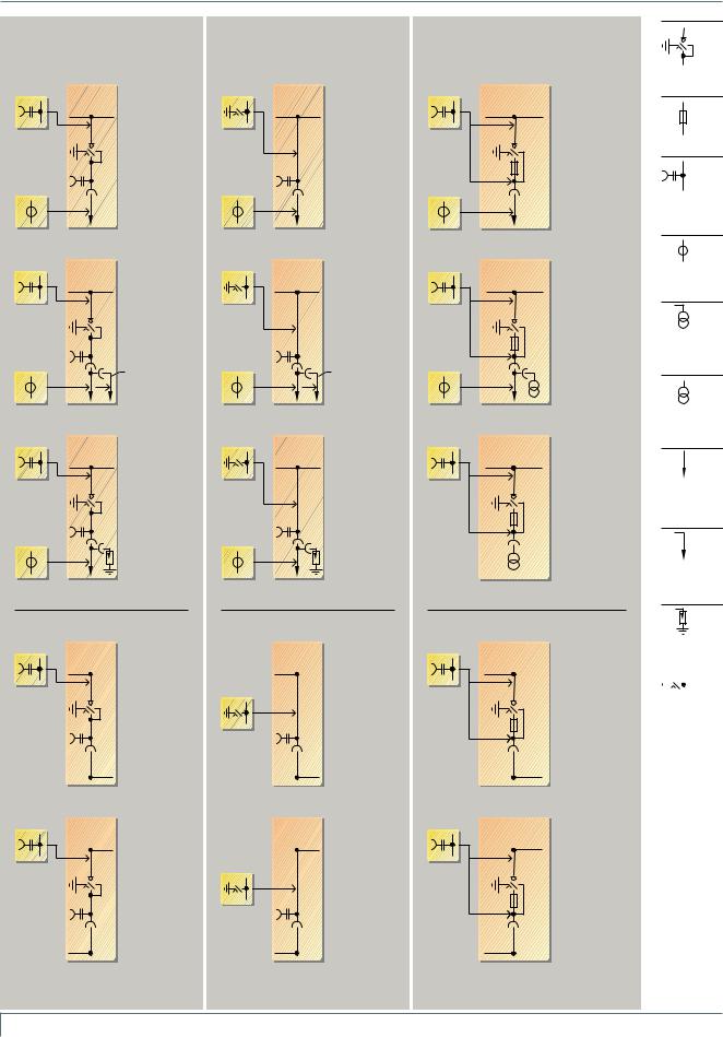
Product Range
Ring-main, cable and transformer panels as individual panels
Ring-main panels |
Cable panels |
Transformer panels |
as feeder panels |
as feeder panels |
as feeder panels |
option |
Type RK |
option |
Type K |
option |
eps |
350 mm wide |
eps |
350 mm wide |
eps |
HA41-2213 1d |
Type RK1 1) 3) |
HA41-2218 1d |
|
HA41-2223 1d |
500 mm wide |
|
|||
|
|
|||
option |
|
option |
|
option |
|
Option: |
|
|
|
|
Type RK1 V 1) 2) 3) |
|
|
|
|
500 mm wide |
|
|
|
Type TR1
500 mm wide
option |
Type RK * |
option |
Type K * |
option |
eps |
350 mm wide |
eps |
350 mm wide |
eps |
HA41-2214 1e |
for 2nd cable* |
HA41-2219 1e |
for 2nd cable * |
HA41-2224 1d |
|
|
|||
option |
** |
option |
** |
option |
|
|
|
Type TR1-V B
500 mm wide
with plug-in voltage transformers
option |
Type RK * |
option |
eps |
350 mm wide |
eps |
HA41-2215 1d |
with plug-in |
HA41-2220 1d |
surge |
||
arresters * |
||
option |
|
option |
Type K *
350 mm wide
with plug-in surge arresters *
option
HA41-2225_1d eps
Type TR-V B
500 mm wide
(105 mm deeper cable compartment cover)
with plug-in voltage transformers instead of cable connection
Three-position switch-disconnector
HV HRC fuse
Capacitive voltage detecting system
**
Cable-type current transformer
4MT8 plug-in voltage transformer at the cable connection
4MT8 plug-in voltage transformer at the connection
Cable (not included in the scope of supply)
2nd cable (not included in the scope of supply)
as transfer panels
option
HA41-2216_1d eps
option
HA41-2217_1d eps
Type RK-U
350 mm wide
for transfer to the right
Option:
Type RK1-U3) Type RK1V-U2) 3)
500 mm wide
Type RK-U
350 mm wide
for transfer to the left
Option:
Type RK1-U3) Type RK1V-U2) 3)
500 mm wide
as transfer panels
Type K-U
350 mm wide
|
for transfer |
option |
to the right |
|
HA41-2221_1d eps
Type K-U
350 mm wide
|
for transfer |
option |
to the left |
|
HA41-2222_1d eps
as transfer panels
option
HA41-2226_1d eps
option
HA41-2227_1d eps
Type TR1-U
500 mm wide
for transfer to the right
Type TR1-U
500 mm wide
for transfer to the left
Plug-in surge arrester
HA41-2278e eps |
|
|
|
|
|
|
|
|
|
|
|
|
|
|
|
|
|
|
|
|
|
|
|
|
|
|
|
|
|
|
|
|
|
|
|
Make-proof |
||||||||
|
earthing switch |
|||||||
Footnotes see page 11
10 Switchgear Type 8DH10, up to 24 kV, Gas-Insulated, Extendable Siemens HA 41.11 2008
Product Range
Ring-main, cable and transformer panels in panel blocks BB
Ring-main panel blocks
Designs and options for each panel, see page 10 RK RK
HA41-2228_1d eps

Type R-B2
700 mm wide
consisting of
2 ring-main panels
RK |
RK |
RK |
HA41-2229_1c eps


Type R-B3
1050 mm wide
consisting of
3 ring-main panels
Transformer panel blocks
Designs and options for each panel, see page 10
|
|
TR |
|
|
TR |
||||||||||||
eps |
|
|
|
|
|
|
|
|
|
|
|
|
|
|
|
|
Type T-B2 |
|
|
|
|
|
|
|
|
|
|
|
|
|
|
|
|||
_1c |
|
|
|
|
|
|
|
|
|
|
|
|
|
|
|
|
1000 mm wide |
-2230 |
|
|
|
|
|
|
|
|
|
|
|
|
|
|
|
|
consisting of |
|
|
|
|
|
|
|
|
|
|
|
|
|
|
|
|||
HA41 |
|
|
|
|
|
|
|
|
|
|
|
|
|
|
|
|
2 transformer panels |
|
|
|
|
|
|
|
|
|
|
|
|
|
|
|
|
|
|
|
|
|
|
|
|
|
|
|
|
|
|
|
|
|
|
|
|
|
|
|
|
|
|
|
|
|
|
|
|
|
|
|
|
|
|
|
|
|
|
|
|
|
|
|
|
|
|
|
|
|
|
|
|
|
|
|
|
|
|
|
|
|
|
|
|
|
|
|
|
|
|
|
|
|
|
|
|
|
|
|
|
|
|
|
|
|
|
|
|
|
TR |
TR |
TR |
|
eps |
|
|
Type T-B3 |
|
1c |
|
|
1500 mm wide |
|
-2231 |
|
|
|
consisting of |
|
|
|
||
HA41 |
|
|
3 transformer |
|
panels
Designs
•Busbar connection system for connection of individual panels or panel blocks: Arranged in the left-hand panel of the panel block (therefore extendable at a later date)
•Only either the left-hand or the right-hand panel of the panel block can be designed as a transfer panel with busbar connection
•Panel blocks are also available without a busbar connection system (extendable at a later date only via the cable feeder)
Ring-main/transformer panel blocks
Designs and options for each panel, see page 10
RK |
TR c |
HA41-2232_1d eps


Type RT-B2
700 mm wide
consisting of
1 ring-main panel and
1 transformer panel
RK |
RK |
TR c |
HA41-2233_1c eps


Type 2RT-B3
1050 mm wide
consisting of
2 ring-main panels and
1 transformer panel
RK |
RK |
RK |
TR c |
eps |
|
|
Type 3RT-B4 |
1c |
|
|
1400 mm wide |
-2234 |
|
|
consisting of |
HA41 |
|
|
3 ring-main panels |
|
|
|
and |
|
|
|
1 transformer |
|
|
|
panel |
Three-position switch-disconnector
HV HRC fuse
Capacitive voltage detecting system
BB Capacitive voltage detecting system at the busbar of the panel blocks: Only located once in the first panel of the block!
eps2278e
-HA41 Cable (not included in the scope of supply)
Cable connection/transformer panel block
Designs and options for each panel, see page 10
K |
TR c |
HA41-2235_1e eps

Type KT-B2
700 mm wide
consisting of
1 cable connection panel
1 transformer panel
Designs
•Busbar connection system for connection of individual panels or panel blocks: Arranged in the left-hand panel of the panel block (therefore extendable at a later date)
•Only either the left-hand or the right-hand panel of the panel block can be designed as a transfer panel with busbar connection
•Panel blocks are also available without a busbar connection system (extendable at a later date only via the cable feeder)
c A plug-in voltage transformer cannot be provided at the connection
Footnotes from page 10
BDeep cable compartment cover required
*Depending on the make/type of the cable
plug or arrester: Deep cable compartment cover required
**Cable-type current trans-
former on the 2nd cable: For 300 mm deeper cable compartment cover
1)Suitable for voltage transformer type 4MT8
2)Suitable for voltage transformer type 4MT3
3)Suitable for three-phase current transformers
Switchgear Type 8DH10, up to 24 kV, Gas-Insulated, Extendable Siemens HA 41.11 2008 11
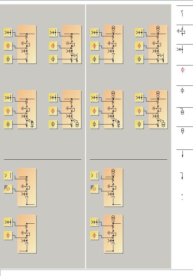
Product Range
Circuit-breaker panels as individual panels BB
Circuit-breaker panels |
Circuit-breaker panels with plug-in |
|
|
|
|
|
|||
|
busbar voltage transformers |
|
|
|
as feeder panels |
as feeder panels |
Vacuum |
||
circuit-breaker |
||||
|
|
|||
option |
option |
|
option |
option |
|
eps |
eps |
|
eps |
eps |
|
option |
option |
|
option |
option |
|
HA412236-1e |
HA412238-1e |
|
HA412242-1e |
HA412244-1e |
|
1) |
1) |
|
1) |
1) |
|
option |
option |
** |
option |
option |
** |
2) |
2) |
|
2) |
2) |
|
Type LS1 |
|
Type LS1 * |
|
Type LS1V/LS2 |
Type LS2 * |
500 mm wide |
|
500 mm wide |
|
500 mm wide |
500 mm wide |
Basic panel |
for 2nd cable * |
Basic panel |
for 2nd cable * |
Three-position switch-disconnector
Capacitive voltage detecting system
1)
4MC63... threephase current transformer
option |
option |
option |
option |
eps |
eps |
eps |
eps |
option |
option |
option |
option |
HA412237-1d |
HA4122391d- |
HA412243-1d |
HA4122451d- |
1) |
1) |
1) |
1) |
option |
option |
option |
option |
2) |
2) |
2) |
2) |
Type LS1 * |
Type LS1 B |
Type LS1V/LS2 * |
Type LS1V/LS2 B |
500 mm wide |
500 mm wide |
500 mm wide |
500 mm wide |
with plug-in |
with plug-in |
with plug-in |
with plug-in |
surge arresters or |
voltage trans- |
surge arresters |
voltage trans- |
limiters * |
formers B |
or limiters * |
formers B |
2)
Cable-type current transformer
on the cable
4MT8 plug-in voltage transformer at the cable connection
4MT3 plug-in voltage transformer at the busbar
as transfer panels
option eps1d 

_2240 -HA41 option

 1)
1)
|
option |
HA41-2241 1d eps |
option |
|
1) |
Type LS1-U
500 mm wide
for transfer to the right
Type LS1-U
500 mm wide
for transfer to the left
as transfer panels
option eps1d 

_2246 -HA41 option

 1)
1)
|
option |
HA41-2247 1d eps |
option |
|
1) |
Type LS1V-U/LS2-U
500 mm wide
for transfer to the right
Type LS1V-U/LS2-U
500 mm wide
for transfer to the left
|
Cable (not |
||||||||
|
included in the |
||||||||
|
scope of supply) |
||||||||
|
|
|
|||||||
|
2nd cable (not |
||||||||
|
included in the |
||||||||
|
scope of supply) |
||||||||
HA41-2278e eps |
|
|
|
|
|
|
|
|
|
|
|
|
|
|
|
|
|
|
|
|
|
|
|
|
|
|
|
||
|
|
|
|
||||||
Plug-in |
|||||||||
|
surge arrester |
||||||||
|
or limiter |
||||||||
Footnotes see page 13
12 Switchgear Type 8DH10, up to 24 kV, Gas-Insulated, Extendable Siemens HA 41.11 2008
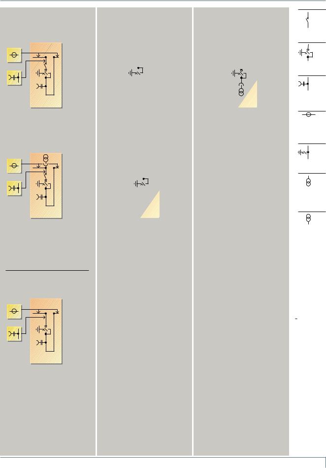
Product Range
Bus sectionalizer with circuit-breaker, bus sectionalizer with switch-disconnector, busbar earthing panels and busbar voltage metering panel as individual panels BB
Bus sectionalizer with circuit-breaker
option epsc
1_ 2248-HA41 option
Type LK/LT1
500 mm wide
with vacuum circuit-breaker
option eps1e
_2249 -HA41 option
Type LKV/LT1-V
500 mm wide
with vacuum circuit-breaker and plug-in voltage transformers
Bus sectionalizer
with switch-disconnector
option epsc
1_ 2250-HA41 option
Type LT2
500 mm wide
Busbar earthing panels
HA41-2252_1b eps
Type SE
350 mm wide
HA41-2253_1c eps
Type SE1V/SE2
500 mm wide
with plug-in voltage transformers
Busbar voltage metering panel
HA41-2254_1c eps
Type MS1V/ME3
500 mm wide
Vacuum circuit-breaker
Three-position switch-disconnector
Capacitive voltage detecting system
Cable-type current transformer on the screened busbar
Make-proof earthing switch
4MT8 plug-in voltage transformer
at the connection
eps2278e
-HA41 4MT3 plug-in voltage
transformer at the busbar
Footnotes from page 12 and 13
BDeep cable compartment cover required
BBShort identifications of the panels have been harmonized
*Depending on the make/type of the cable
plug or arrester: Deep cable compartment cover required
**Cable-type current trans-
former on the 2nd cable: For 300 mm deeper cable
compartment
Switchgear Type 8DH10, up to 24 kV, Gas-Insulated, Extendable Siemens HA 41.11 2008 13
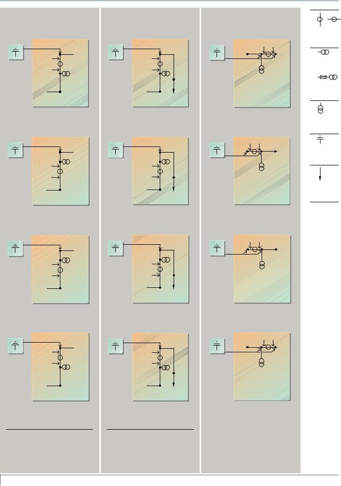
Product Range
Air-insulated metering panels as transfer panels
Billing metering panels (standard)
option
HA41-2258_1c eps
option
HA41-2259_1c eps
option
HA41-2260_1c eps
option
HA41-2261_1c eps
P2
P1 1)
Scheme 1
Type ME1, 850 mm wide
for transfer to the right
1)
P2
P1
Scheme 2
Type ME1, 850 mm wide
for transfer to the right, transformer terminals interchanged
1)
P1
P2
Scheme 3
Type ME1, 850 mm wide
for transfer to the right
P1
P2 1)
Scheme 4
Type ME1, 850 mm wide
for transfer to the right, transformer terminals interchanged
Note
Schemes 1 to 4 also feasible for transfer to the left
Billing metering panels as end panels, for cable connection
option
HA41-2262_1b eps
option
HA41-2263_1b eps
option
HA41-2264_1b eps
option
HA41-2265_1b eps
P2
P1
Scheme 1
Type ME1-K, 850 mm wide
for transfer to the right
P2
P1
Scheme 2
Type ME1-K, 850 mm wide
for transfer to the right, transformer terminals interchanged
P1
P2
Scheme 3
Type ME1-K, 850 mm wide
for transfer to the right
P1
P2
Scheme 4
Type ME1-K, 850 mm wide
for transfer to the right, transformer terminals interchanged
Note
Schemes 1 to 4 also feasible for transfer to the left
Billing metering panels for busbar connection
option
HA41-2266_1c eps
option
HA41-2267_1c eps
option
HA41-2436_1a eps
option
HA41-2437_1a eps
P1 P2
Scheme 1
Type ME1-S, 850 mm wide
for busbar metering
P1 P2
Scheme 2
Type ME1-S, 850 mm wide
for busbar metering, transformer terminals interchanged
P2 P1
Scheme 3
Type ME1-S, 850 mm wide
for busbar metering, transformer terminals interchanged
P2 P1
Scheme 4
Type ME1-S, 850 mm wide
for busbar metering, transformer terminals interchanged
HA41-2278d eps
Current transformer, cast-resin insulated
1)
Voltage transformer, cast-resin insulated or on request:
Voltage transformer, cast-resin insulated, with HV HRC fuse
Voltage transformer, cast-resin insulated
Fixed earthing points for busbar earthing
Cable (not included in the scope of supply)
P1 and P2 are terminal designations of the current transformer
14 Switchgear Type 8DH10, up to 24 kV, Gas-Insulated, Extendable Siemens HA 41.11 2008
 Loading...