


SINUMERIK System 800
Universal Interface
Planning Guide |
Edition 12.95 |
Manufacturer Documentation
SINUMERIK
System 800
Universal Interface
Planning Guide
Manufacturer Documentation
Valid for: |
|
Control |
Software Version |
SINUMERIK 805 |
2 |
SINUMERIK 810 T / 810 TE (GA 1) |
2 |
SINUMERIK 810 M / 810 ME (GA 1) |
2 |
SINUMERIK 810 G |
1 |
SINUMERIK 810 T / 810 TE (GA 2) |
2 |
SINUMERIK 810 M / 810 ME (GA 2) |
2 |
SINUMERIK 820 T/ TE |
2 |
SINUMERIK 820 M/ ME |
2 |
SINUMERIK 810 T / 810 TE (GA 3) |
1 |
SINUMERIK 810 M / 810 ME (GA 3) |
1 |
SINUMERIK 820 T/ TE (GA 3) |
1 |
SINUMERIK 820 M/ ME (GA 3) |
1 |
SINUMERIK 840T |
1 |
SINUMERIK 840M |
1 |
SINUMERIK 840C |
5 |
SINUMERIK 850 T/ TE |
4 |
SINUMERIK 850 M/ ME |
4 |
SINUMERIK 880 T/ TE |
5 |
SINUMERIK 880 M/ ME |
5 |
SINUMERIK 880 N |
4 |
December 1995 Edition
SINUMERIK® documentation
Printing history
Brief details of this edition and previous editions are listed below.
The status of each edition is shown by the code in the ºRemarksº column.
Status code in ºRemarksº column: |
|
|
A . . . . |
New documentation |
B . . Unrevised reprint with new Order No. |
C . . . . |
Revised edition with new status. If factual changes have been made on the page since |
|
the last edition, this is indicated by a new edition coding in the header on that page. |
||
Edition |
Order No. |
Remarks |
10.86 |
E80210-T77-X-A3 |
Revised edition |
10.88 |
6ZB5 410-0AQ02-0BA0 |
C |
07.90 |
6ZB5 410-0AQ02-0BA1 |
C |
07.90 |
6ZB5 410-0AQ02-0BA2 |
C |
03.91 |
6ZB5 410-0AQ02-0AA3 |
C |
12.95 |
6ZB5 410-0AQ02-0AA4 |
C |
Other functions not described in this documentation might be executable in the control. This does not, however, represent an obligation to supply such functions with a new control or when servicing.
This publication was produced on the Siemens 5800 Office
System.
Subject to change without prior notice.
The reproduction, transmission or use of this document or its contents is not permitted without express written authority. Offenders will be liable for damages. All rights, including rights created by patent grant or registration of a utility model or design, are reserved.
© Siemens AG 1986, 1988, 1990, 1991, 1995 All Rights Reserved
Preface
Notes for the reader
This documentation is intended for manufacturers of machine tools with the SINUMERIK System 800.
It describes data exchange with input/output devices (e.g. tape reader, tape punch, programmer, printer, magnetic tape unit, etc).
The SINUMERIK documentation is divided into three parts:
·General Documentation
·User Documentation
·Manufacturer Documentation
·Service Documentation
The manufacturer documentation for the SINUMERIK System 800 controller is divided into the following parts:
·Instruction Manual
·Interface
Part 1: Signals
Part 2: Cables and Devices
·PLC Programming Guide
·Function Blocks
·Universal Interface
·Measuring Cycles
·CL - 800 Description
You can obtain more detailed information from your Siemens representative.
V.24 (RS232C) Interface |
1 |
|
|
|
|
20 mA Current Loop Interface |
2 |
|
|
|
|
RS 422 Interface |
3 |
|
|
|
|
Interface Overview |
4 |
|
|
|
|
Adapting the Interfaces to I/O Devices |
5 |
|
|
|
|
Signal Timing for Data Transmission |
6 |
|
|
|
|
Serial Interfaces on the SINUMERIK System 800 |
7 |
|
|
|
|
Connecting I/O Devices in Practice |
8 |
|
|
|
|
Contents
|
|
Page |
1 |
V.24 (RS232) Interface . . . . . . . . . . . . . . . . . . . . . . . . . . . . . . . . . . |
1-1 |
1.1 |
General notes . . . . . . . . . . . . . . . . . . . . . . . . . . . . . . . . . . . . . . . . . |
1-1 |
1.2 |
V.24 (RS232C) interface lines . . . . . . . . . . . . . . . . . . . . . . . . . . . . . . |
1-1 |
1.3 |
Polarity and voltage level assignment of V.24 interface signals . . . . . . . |
1-3 |
1.4 |
V.24 drivers and receivers . . . . . . . . . . . . . . . . . . . . . . . . . . . . . . . . . |
1-4 |
1.4.1 |
V.24 drivers . . . . . . . . . . . . . . . . . . . . . . . . . . . . . . . . . . . . . . . . . . . |
1-4 |
1.4.2 |
V.24 receivers . . . . . . . . . . . . . . . . . . . . . . . . . . . . . . . . . . . . . . . . . |
1-4 |
1.5 |
Interface link to I/O device for V.24 . . . . . . . . . . . . . . . . . . . . . . . . . . |
1-5 |
1.6 |
Length of the transmission line . . . . . . . . . . . . . . . . . . . . . . . . . . . . . |
1-6 |
2 |
20 mA Current Loop Interface . . . . . . . . . . . . . . . . . . . . . . . . . . . . |
2-1 |
2.1 |
General notes . . . . . . . . . . . . . . . . . . . . . . . . . . . . . . . . . . . . . . . . . |
2-1 |
2.2 |
20 mA signal level . . . . . . . . . . . . . . . . . . . . . . . . . . . . . . . . . . . . . . |
2-1 |
2.3 |
Interface link to I/O device for 20 mA . . . . . . . . . . . . . . . . . . . . . . . . . |
2-2 |
2.3.1 |
Duplex interface active at SINUMERIK end . . . . . . . . . . . . . . . . . . . . . |
2-3 |
2.3.2 |
Duplex interface passive at the SINUMERIK end . . . . . . . . . . . . . . . . . |
2-4 |
2.4 |
Length of the transmission line . . . . . . . . . . . . . . . . . . . . . . . . . . . . . |
2-4 |
3 |
RS 422 Interface . . . . . . . . . . . . . . . . . . . . . . . . . . . . . . . . . . . . . . . |
3-1 |
3.1 |
General notes . . . . . . . . . . . . . . . . . . . . . . . . . . . . . . . . . . . . . . . . . |
3-1 |
3.2 |
Polarity and voltage level assignment of the RS 422 interface . . . . . . . . |
3-2 |
3.3 |
RS 422 drivers and receivers . . . . . . . . . . . . . . . . . . . . . . . . . . . . . . |
3-3 |
3.3.1 |
RS 422 driver . . . . . . . . . . . . . . . . . . . . . . . . . . . . . . . . . . . . . . . . . |
3-3 |
3.3.2 |
RS 422 receiver . . . . . . . . . . . . . . . . . . . . . . . . . . . . . . . . . . . . . . . . |
3-3 |
3.4 |
Interface link to I/O device for RS 422 . . . . . . . . . . . . . . . . . . . . . . . . |
3-4 |
3.5 |
Length of the transmission line . . . . . . . . . . . . . . . . . . . . . . . . . . . . . |
3-4 |
3.6 |
Level conversion from V.24 to RS 422 . . . . . . . . . . . . . . . . . . . . . . . . |
3-4 |
4 |
Interface Overview . . . . . . . . . . . . . . . . . . . . . . . . . . . . . . . . . . . . . |
4-1 |
4.1 |
Pin assignments of the data interfaces . . . . . . . . . . . . . . . . . . . . . . . . |
4-1 |
4.1.1 |
Pin assignments of the V.24/20 mA universal interface . . . . . . . . . . . . |
4-1 |
4.1.2 |
Pin assignments of the RS 422 interface . . . . . . . . . . . . . . . . . . . . . . |
4-2 |
4.2 |
Explanation of signal names . . . . . . . . . . . . . . . . . . . . . . . . . . . . . . . |
4-3 |
4.3 |
Format of a serially transmitted character . . . . . . . . . . . . . . . . . . . . . |
4-3 |
4.4 |
Block diagram of the data interfaces . . . . . . . . . . . . . . . . . . . . . . . . . |
4-4 |
4.4.1 |
Block diagram of a V.24/20 mA universal interface . . . . . . . . . . . . . . . |
4-4 |
4.4.2 |
Block diagram of an RS 422 interface . . . . . . . . . . . . . . . . . . . . . . . . |
4-5 |
5 |
Adapting the Interfaces to I/O Devices . . . . . . . . . . . . . . . . . . . . . . |
5-1 |
5.1 |
General notes . . . . . . . . . . . . . . . . . . . . . . . . . . . . . . . . . . . . . . . . . |
5-1 |
5.2 |
Setting data . . . . . . . . . . . . . . . . . . . . . . . . . . . . . . . . . . . . . . . . . . . |
5-2 |
5.2.1 |
Explanation of the setting data . . . . . . . . . . . . . . . . . . . . . . . . . . . . . . |
5-3 |
5.3 |
Notes on the format of special characters . . . . . . . . . . . . . . . . . . . . . . |
5-6 |
5.4 |
Notes on using the EIA code . . . . . . . . . . . . . . . . . . . . . . . . . . . . . . . |
5-6 |
6 |
Signal Timing for Data Transmission . . . . . . . . . . . . . . . . . . . . . . . |
6-1 |
6.1 |
Signal timing with line-controlled devices . . . . . . . . . . . . . . . . . . . . . . |
6-1 |
6.1.1 |
Data input (I/O device to the NC) . . . . . . . . . . . . . . . . . . . . . . . . . . . . |
6-1 |
6.1.2 |
Data output (NC to I/O device) . . . . . . . . . . . . . . . . . . . . . . . . . . . . . |
6-2 |
6.2 |
Signal timing with character-controlled devices . . . . . . . . . . . . . . . . . . |
6-4 |
6.2.1 |
Data input (I/O device to NC) . . . . . . . . . . . . . . . . . . . . . . . . . . . . . . |
6-4 |
6.2.2 |
Data output (NC to I/O device) . . . . . . . . . . . . . . . . . . . . . . . . . . . . . |
6-5 |
7 |
Serial Interfaces on the SINUMERIK System 800 . . . . . . . . . . . . . . |
7-1 |
7.1 |
Interfaces on the various controls . . . . . . . . . . . . . . . . . . . . . . . . . . . |
7-1 |
7.1.1 |
SINUMERIK 805 . . . . . . . . . . . . . . . . . . . . . . . . . . . . . . . . . . . . . . . |
7-1 |
7.1.2 |
SINUMERIK 810 GA1 . . . . . . . . . . . . . . . . . . . . . . . . . . . . . . . . . . . . |
7-1 |
7.1.3 |
SINUMERIK 810GA2/820GA2 . . . . . . . . . . . . . . . . . . . . . . . . . . . . . . |
7-2 |
7.1.4 |
SINUMERIK 810 GA3/820 GA3 . . . . . . . . . . . . . . . . . . . . . . . . . . . . . |
7-2 |
7.1.5 |
SINUMERIK 840 . . . . . . . . . . . . . . . . . . . . . . . . . . . . . . . . . . . . . . . |
7-3 |
7.1.6 |
SINUMERIK 850 . . . . . . . . . . . . . . . . . . . . . . . . . . . . . . . . . . . . . . . |
7-4 |
7.1.7 |
SINUMERIK 880 . . . . . . . . . . . . . . . . . . . . . . . . . . . . . . . . . . . . . . . |
7-5 |
7.2 |
Setting data for the various controls . . . . . . . . . . . . . . . . . . . . . . . . . . |
7-6 |
8 |
Connecting I/O Devices in Practice . . . . . . . . . . . . . . . . . . . . . . . . |
8-1 |
8.1 |
Device setting data . . . . . . . . . . . . . . . . . . . . . . . . . . . . . . . . . . . . . . |
8-1 |
8.2 |
Device connection data . . . . . . . . . . . . . . . . . . . . . . . . . . . . . . . . . . . |
8-5 |
8.2.1 |
Siemens PT 80 page printer . . . . . . . . . . . . . . . . . . . . . . . . . . . . . . . |
8-5 |
8.2.2 |
Siemens PT 88 printer . . . . . . . . . . . . . . . . . . . . . . . . . . . . . . . . . . . |
8-5 |
8.2.3 |
SINUMERIK T40 and T50 tape readers . . . . . . . . . . . . . . . . . . . . . . . |
8-6 |
8.2.4 |
SINUMERIK T60 tape reader (hand-held) . . . . . . . . . . . . . . . . . . . . . . |
8-7 |
8.2.5 |
Sanyo M2502U cassette . . . . . . . . . . . . . . . . . . . . . . . . . . . . . . . . . |
8-7 |
8.2.6 |
ASR3320/3WE teletype . . . . . . . . . . . . . . . . . . . . . . . . . . . . . . . . . . |
8-8 |
8.2.7 |
Facit 4040, 4042 punch/tape reader combination. . . . . . . . . . . . . . . . . |
8-9 |
8.2.8 |
Facit 4070 punch . . . . . . . . . . . . . . . . . . . . . . . . . . . . . . . . . . . . . . . |
8-9 |
8.2.9 |
Facit 4030 tape reader . . . . . . . . . . . . . . . . . . . . . . . . . . . . . . . . . . . |
8-10 |
8.2.10 |
Facit N 1000 NC Walk-Disk . . . . . . . . . . . . . . . . . . . . . . . . . . . . . . . . |
8-10 |
8.2.11 |
Facit N 1100 NC Walk-Disk . . . . . . . . . . . . . . . . . . . . . . . . . . . . . . . . |
8-11 |
8.2.12 |
Siemens DSG 3.5 floppy disk drive . . . . . . . . . . . . . . . . . . . . . . . . . . |
8-11 |
8.2.13 |
Siemens DSG 2S floppy disk drive . . . . . . . . . . . . . . . . . . . . . . . . . . |
8-12 |
8.2.14 |
Sommer MDC-3 SNC cartridge drive terminal . . . . . . . . . . . . . . . . . . . |
8-12 |
8.2.15 |
Tekelec FDS 300, FDS 500 floppy disk drive . . . . . . . . . . . . . . . . . . . |
8-13 |
8.2.16 |
Tekelec Magnetic Tape Cartridge Drive, Model CDS 1.58 . . . . . . . . . . |
8-13 |
8.2.17 |
CAN NC Recorder FD/FH . . . . . . . . . . . . . . . . . . . . . . . . . . . . . . . . . |
8-14 |
8.2.18 |
GNT 7101 NC data Carrier . . . . . . . . . . . . . . . . . . . . . . . . . . . . . . . . |
8-14 |
8.2.19 |
GNT 4604 tape reader/punch station . . . . . . . . . . . . . . . . . . . . . . . . . |
8-15 |
8.2.20 |
SINUMERIK WS 800, programming workstation . . . . . . . . . . . . . . . . . |
8-15 |
8.2.21 |
SINUMERIK WS 800 A, programming workstation . . . . . . . . . . . . . . . |
8-16 |
8.2.22 |
SIMATIC PG 675/685/635 programmer (PG IN) . . . . . . . . . . . . . . . . . . |
8-16 |
8.2.23 |
SIMATIC 750 programmer (PC IN) . . . . . . . . . . . . . . . . . . . . . . . . . . . |
8-17 |
8.2.24 |
SINUMERIK System 800, RS 232 C, NC-NC link . . . . . . . . . . . . . . . . |
8-17 |
8.2.25 |
SINUMERIK T30 tape reader . . . . . . . . . . . . . . . . . . . . . . . . . . . . . . . |
8-18 |
8.2.26 |
Siemens T10 and T20 tape reader . . . . . . . . . . . . . . . . . . . . . . . . . . . |
8-18 |
8.2.27 |
Siemens PD ... PG programming workstation . . . . . . . . . . . . . . . . . . . |
8-19 |
8.2.28 |
SIMATIC PG 670/675/685/635/750 programmer . . . . . . . . . . . . . . . . . |
8-20 |
8.2.29 |
SIMATIC PG 750 programmer (PLC progamming) . . . . . . . . . . . . . . . . |
8-21 |
8.2.30 |
SIMATIC PG 615 programmer . . . . . . . . . . . . . . . . . . . . . . . . . . . . . . |
8-22 |
8.3 |
Ordering data of the connecting cables . . . . . . . . . . . . . . . . . . . . . . . |
8-23 |
8.4 |
Device cable diagrams . . . . . . . . . . . . . . . . . . . . . . . . . . . . . . . . . . . |
8-25 |
10.88 |
1 V.24 (RS232C) Interface |
1.1 General notes
1 V.24 (RS 232 C) Interface
1.1General notes
The V.24 interfaces of the SINUMERIK System 800 contain V.24 receivers and V.24 senders, conforming to DIN 66020.
DIN 66020 defines the interface between a DTE (data terminal equipment) and a DCE (data circuit terminating equipment). It is based on recommendations V.24 and V.28 of the CCITT, which were derived from the American EIA Standard RS 232.
The interfaces also conform to VDI guideline 2880, which specifies process and data traffic of programmable controllers.
The interface signals used in SINUMERIK System 800 are a subset of V.24 or RS 232 standard signals and therefore possess the same electrical characteristics.
1.2V.24 (RS232C) interface lines
In terms of the DIN standard, SINUMERIK is regarded as a DTE (data terminal equipment).
SINUMERIK |
± |
DTE |
Transmission line |
± |
DCE |
I/O devices |
± |
DTE |
The abbreviations E1, E2, D1, D2, S1.2, S2, M1, M2 refer to DIN 66020, the abbreviations 101 to 108.2 refer to CCITT (V.24).
Ground lines
E1: |
Protective Ground |
|
(101) |
E2: |
Signal Ground |
|
(102) |
|
This is the common return cable for all interface lines |
|
(except E1). |
© Siemens AG 1990 All Rights Reserved 6ZB5 410-0AQ02 |
1-1 |
SINUMERIK System 800, (PJ)
1 V.24 (RS232C) Interface |
10.88 |
1.2 V.24 interface lines |
|
Data lines
D1: |
Transmitted Data |
|
(103 - TxD) |
|
On this line data is transmitted from the DTE to the DCE. |
|
Quiescent state is logic ©©High©©. |
D2: |
Received Data |
|
(104 - RxD) |
|
On this line data is transmitted to the DTE from the DCE. |
|
Quiescent state is logic ©©High©©. |
Control lines |
|
S1.2: |
Data Terminal Ready |
|
(108/2 - DTR) |
|
The DTE signals to the DCE that it is ready for data transmission. |
S2: |
Request to Send |
|
(105 - RTS) |
|
The DTE controls the send part of the data channel of the DCE. |
Message lines |
|
M1: |
Data Set Ready |
|
(107 ± DSR) |
|
The DCE signals to the DTE whether or not it is ready for transmission. |
M2: |
Clear to Send |
|
(106 ± CTS) |
|
The DCE signals to the DTE whether or not it is ready to send data signals through |
|
the data channel. |
1-2 |
© Siemens AG 1990 All Rights Reserved 6ZB5 410-0AQ02 |
SINUMERIK System 800, (PJ)
10.88 |
1 V.24 (RS232C) Interface Lines |
1.3Polarity and voltage level assignment of V.24 interface signals
1.3Polarity and voltage level assignment of V.24 interface signals
V |
|
Data lines |
+15 |
V |
|
+12 |
V |
|
|
|
Logical ©©L©© |
+3 |
V |
|
0 V |
t |
|
±3 V |
|
|
|
|
Logical ©©H©© |
±12 V |
|
|
±15 V |
|
|
V |
|
Control lines |
+15 |
V |
|
+12 |
V |
|
©©On©© state
+3 V |
|
|
|
|
|
|
|
|
|
|
|
|
|
|
|
|
|
|
|
|
|
|
|
|
|
|
|
|
|
|
|
|
|
|
|
|
|
|
|
|
|
|
|
|
|
|
|
|
|
|
|
|
|
|
|
|
|
|
|
|
|
|
|
|
|
|
|
||
0 V |
|
|
|
|
|
|
|
|
|
|
|
|
|
|
|
|
|
|
|
|
|
|
|
|
|
|
|
|
|
|
|
|
|
t |
|
|
|
|
|
|
|
|
|
|
|
|
|
|
|
|
|
|
|
|
|
|
|
|
|
|
|
|
|
|
|
|
|||
±3 V |
|
|
|
|
|
|
|
|
|
|
|
|
|
|
|
|
|
|
|
|
|
|
|
|
|
|
|
|
|
|
|
|
|
|
|
|
|
|
|
|
|
|
|
|
|
|
|
|
|
|
|
|
|
|
|
|
|
|
|
|
|
|
|
|
|
|
|
||
|
|
|
|
|
|
©©Off©© state |
|
|
||||||||||||||||||||||||||
|
|
|
|
|
|
|
|
|||||||||||||||||||||||||||
±12 V |
|
|
|
|
|
|
|
|
|
|
|
|
|
|
|
|
|
|
|
|
|
|
|
|
|
|
|
|
|
|
|
|
|
|
|
|
|
|
|
|
|
|
|
|
|
|
|
|
|
|
|
|
|
|
|
|
|
|
|
|
|
|
|
|
|
|
|
||
±15 V |
|
|
|
|
|
|
|
|
|
|
|
|
|
|
|
|
|
|
|
|
|
|
|
|
|
|
|
|
|
|
|
|
|
|
|
|
|
|
|
|
|
|
|
|
|
|
|
|
|
|
|
|
|
|
|
|
|
|
|
|
|
|
|
|
|
|
|
||
Signal level of SINUMERIK interfaces: ±12 V
All signal levels refer to the signal ground E2 (102).
Within the transition range (+3 to ±3 V) the signal state is undefined. (Hysteresis range of the receiver circuits 75189 A)
© Siemens AG 1990 All Rights Reserved 6ZB5 410-0AQ02 |
1-3 |
SINUMERIK System 800, (PJ)
1 V.24 (RS232C) Interface |
10.88 |
1.4 V.24 drivers and receivers
1.4V.24 drivers and receivers
1.4.1V.24 drivers
The V.24 output signals *TxD, RTS and DTR are generated in the V.24 driver block 75188 from the TTL signals of the USART 8251A.
|
|
|
|
TTL level |
Data of circuit 75188 |
|
|||||
|
|
|
|
|
|||||||
|
|
|
|
|
|
|
|
|
|
Vcc ± 15 V |
|
|
|
|
|
|
|
|
|
|
|
||
|
|
|
|
|
|
|
|
|
|
Max. supply voltage |
|
|
|
|
|
|
|
|
|
|
+12 V |
||
75 188 |
& |
|
|
|
|
|
Max. output current |
|
|||
|
|
|
|
|
0 V |
(current limited) |
Io 10 mA |
||||
|
|
|
|
|
|
|
|
|
|||
|
|
|
|
|
|
|
|
|
Operating voltage |
Vcc± 12 V |
|
|
|
|
|
|
|
|
|
|
±12 V |
and V.24 level |
|
|
|
|
|
|
|
|
|
|
|||
|
|
|
|
|
|
|
|
|
|
|
|
|
|
|
|
|
|
|
|
|
|
|
|
|
|
|
V.24 level |
|
|
||||||
|
|
|
|
|
|
|
|
|
|
|
|
|
|
|
|
|
|
|
|
|
|
|
|
1.4.2V.24 receivers
The V.24 input signals * RxD, CTS and DSR are put onto the receiver circuits 75189 after passing through an RC low-pass filter.
Vc |
|
|
|
|
|
|
|
|
V.24 level |
|
|||||||
|
|
|
|
|
|
|
|
|
|
|
|
|
|
|
|
Data of circuit 75189A |
|
4.7 k |
|
|
|
|
|
|
|
390 |
Max. input voltage |
Vcc ± 30 V |
|||||||
|
|
|
|
|
|
|
|
|
|
|
|
|
|
|
|
||
|
|
|
|
|
|
|
|
|
|
|
|
|
|
|
|
Input resistance |
390 |
|
|
|
|
|
|
|
|
|
|
|
|
|
|
|
|||
|
|
|
|
|
|
|
|
|
|
|
|
|
|
|
|
||
75 189 A
TTL level
1-4 |
© Siemens AG 1990 All Rights Reserved 6ZB5 410-0AQ02 |
SINUMERIK System 800, (PJ)

07.90 |
1 V.24 (RS232C) Interface |
1.5 |
Interface link to I/O device for V.24 |
1.5Interface link to I/O device for V.24
SINUMERIK |
|
|
|
|
|
No device |
DTE |
|
|
|
DCE |
|
DTE |
|
2 |
|
Transmitted data |
3 |
|
|
* T x D |
O |
|
O |
* R x D |
||
|
D1 |
(103) |
||||
|
|
|
||||
|
3 |
|
Received data |
2 |
|
|
* R x D |
O |
|
O |
* T x D |
||
|
D2 |
(104) |
||||
|
|
|
|
|
||
|
4 |
|
Request to send |
5 |
|
|
RTS |
O |
|
O |
CTS |
||
|
S2 |
(105) |
||||
|
|
|
|
|
||
CTS |
5 |
|
Clear to send |
4 |
|
|
O |
|
O |
RTS |
|||
|
M2 |
(106) |
||||
|
|
|
|
|
||
|
6 |
|
Data set ready |
20 |
|
|
|
|
|
|
|||
|
O |
|
O |
|
||
DSR |
|
M1 |
(107) |
DTR |
||
|
|
|
||||
DTR |
20 |
|
Data terminal ready |
6 |
DSR |
|
O |
|
O |
||||
|
|
S1.2(108.2) |
|
|||
|
|
|
|
|
||
|
7 |
|
Signal ground |
7 |
|
|
MEXT |
O |
|
O |
G |
||
|
E2 |
(102) |
||||
|
|
|
||||
|
1 |
Protective ground |
1 |
|
||
|
O |
E1 |
(101) |
O |
|
|
|
|
|
|
|||
In all signal names and directions, the SINUMERIK is taken to be a DTE.
Which of the available control and message lines are used will depend on the I/O device. In the simplest case, lines E2 and D1 suffice for a receiving device (printer, punch) or E2 and D2 for a sending device (reader). The specification of an I/O device determines how it is connected.
In the interface link diagram, a device is assumed to comply with the RS232C standard. The interfaces conform to VDI guideline 2880 with SINUMERIK as a DTE. If it is linked to an I/O device which is also wired as a DTE, the appropriate lines must be crossed in the cable (sender with receiver).
© Siemens AG 1990 All Rights Reserved 6ZB5 410-0AQ02 |
1-5 |
SINUMERIK System 800, (PJ)
1 V.24 (RS232C) Interface |
10.88 |
1.5 Interface link to I/O device for V.24
Some of the interfaces contain both the V.24 signals and the signals for 20 mA current loop operation. A V.24 sender and a 20 mA sender may not be connected to a SINUMERIK interface at the same time.
As pins 10, 12, 13, 14, 16, 19, 21 and 24 are permanently reserved for |
the 20 mA interface at the SINUMERIK end, it is important to make sure |
that they are not connected to the I/O device in V.24 mode. |
The interface is not set to V.24 or 20 mA operation by jumpers but by the pin assignments in the cable plug.
1.6Length of the transmission line
The maximum cable length for V.24 transmission is 30 m.
END OF SECTION
1-6 |
© Siemens AG 1990 All Rights Reserved 6ZB5 410-0AQ02 |
SINUMERIK System 800, (PJ)

10.88 |
2 20 mA Current Loop Interface |
2.1 General notes
2 20 mA Current Loop Interface
2.1General notes
The 20 mA interface is configured to VDI guideline 2880 as a duplex interface with two pairs of lines. At the SINUMERIK end it can be operated as an active or passive interface with the available sources of current by changing the pin assignments in the cable connector. This interface is also often referred to as a TTY interface.
The following is equivalent in V.24 and 20 mA interfaces (except the signal level):
|
|
20 mA |
||
Signal |
V.24 |
|
|
|
+ |
± |
|||
|
|
|||
|
|
|
|
|
Transmitted data |
D1 |
TTY2 |
TTY1 |
|
Received data |
D2 |
TTY4 |
TTY3 |
|
|
|
|
|
|
In the signal designations, the SINUMERIK is taken to be a DTE.
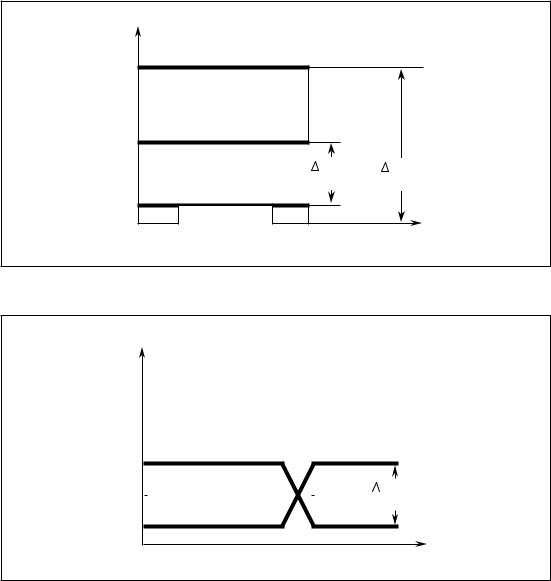
2.220 mA signal level
In the 20 mA interface, unlike the V.24 interface, information is not transmitted by the voltage level but by impressed current.
I |
|
|
|
|
Logical ºLº: |
I=0 |
|||
|
|
||||||||
|
|
|
Logical ºHº |
Logical ºHº: |
I=20 mA |
||||
|
|
|
|
|
|
|
|
||
|
|
|
|
|
Level 1 Signal |
20 mA±30 % |
|||
|
|
|
( 0 V ) |
||||||
I=20 mA |
|
|
|
(max. open-circuit voltage |
|||||
|
|
|
|
|
30 V) |
||||
|
|
|
|
|
|
|
|
||
|
|
|
|
|
|
|
|
0 signal 0 mA to 2 mA |
|
|
|
|
|
|
Voltage for current loop source at |
||||
|
|
|
|
|
SINUMERIK =12 V |
||||
|
|
|
|
|
Logical ºLº |
|
|
||
I= 0 |
|
|
|
|
|
||||
|
|
|
|
|
|
|
|
||
|
|
|
|
|
|
t |
|||
|
|
|
|
|
|
|
|
||
|
|
|
|
|
(12 V) |
||||
|
|
|
|
|
|
|
|||
|
|
|
|
|
|
|
|
|
|
© Siemens AG 1990 All Rights Reserved 6ZB5 410-0AQ02 |
2-1 |
SINUMERIK System 800, (PJ)
2 20 mA Current Loop Interface |
10.88 |
2.3 Interface link to I/O device for 20 mA
2.3Interface link to I/O device for 20 mA
20 mA interfaces are duplex interfaces with two pairs of lines. They can be operated as active or passive interfaces at the SINUMERIK end.
·Active interface:
SINUMERIK supplies the 20 mA line current.
·Passive interface:
The peripheral unit supplies the 20 mA line current.
The interface is set to ©©active©© or ©©passive©© at the SINUMERIK end by the wiring in the cable connector not by jumper setting on the module.
The line current should always be checked when the loop is closed (approx. 20 mA).
Refer also to Section 1.5.
2-2 |
© Siemens AG 1990 All Rights Reserved 6ZB5 410-0AQ02 |
SINUMERIK System 800, (PJ)
07.90 |
2 20 mA Current Loop Interface |
|
2.3.1 Duplex interface |
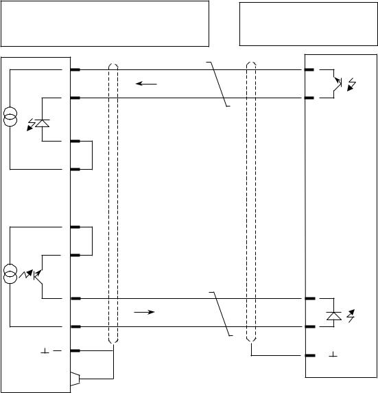
2.3.1 Duplex interface Active at SINUMERIK end
SINUMERIK |
|
|
|
DTE |
|
DCE |
|
0 V (R) |
24 |
Received data ± |
|
|
O |
|
|
|
14 |
Received data + |
|
TTY 3 |
O |
||
|
|||
± |
|
|
|
+ |
13 |
|
|
TTY 4 |
|
||
O |
|
||
|
|
||
R 20 mA |
16 |
|
|
|
O |
|
|
0 V (T) |
21 |
|
|
|
O |
|
|
TTY 1 |
O19 |
|
|
± |
|
|
|
+ |
10 |
Transmitted data ± |
|
TTY 2 |
O |
||
|
|||
|
|
||
T 20 mA |
12 |
Transmitted data + |
|
O |
|||
|
|
||
|
O1 |
|
I/O device
DTE
19 O
10 O
14 O
13
O
1 O
© Siemens AG 1990 |
All Rights Reserved 6ZB5 410-0AQ02 |
2-3 |
SINUMERIK System |
800, (PJ) |
|

2 20 mA Current Loop Interface |
10.88 |
2.3.2 Duplex interface |
|
2.3.2 Duplex interface Passive at the SINUMERIK end
SINUMERIK |
|
|
|
I/O device |
|
DTE |
|
DCE |
|
DTE |
|
|
|
|
21 O |
||
|
O24 |
|
19 |
O |
|
|
14 |
|
10 |
± |
|
|
Received data ± |
|
|||
TTY 3 |
O |
|
O |
||
|
|
||||
± |
|
|
|
|
|
|
|
|
|
+ |
|
+ |
13 |
Received data + |
12 |
|
|
TTY 4 |
|
||||
O |
|
|
O |
||
|
|
|
|||
|
O16 |
|
|
|
|
|
21 |
|
|
|
|
|
O |
|
|
|
|
± |
19 |
Transmitted data + |
24 |
O |
|
O |
|
|
|||
TTY 1 |
|
|
|
|
|
+ |
10 |
|
14 |
± |
|
Transmitted data ± |
O |
||||
TTY 2 |
O |
||||
|
|||||
|
|
|
|||
|
12 |
|
|
+ |
|
|
|
13 |
O |
||
|
O |
|
|||
|
1 |
|
16 |
O |
|
|
O |
|
|
|
|
|
|
|
1 |
O |
|
In all signal names and directions, the SINUMERIK is taken to be a DTE. The specification of the I/O device determines how it is connected.
In the interface link diagram, the I/O device is assumed to comply with the VDI 2880 specification.
2.4Length of the transmission line
The maximum cable length for the 20 mA current loop interface is 1 km.
END OF SECTION
2-4 |
© Siemens AG 1990 All Rights Reserved 6ZB5 410-0AQ02 |
SINUMERIK System 800, (PJ)
10.88 |
3 RS 422 Interface |
3.1 General notes
3 RS 422 Interface
3.1General notes
The function of the signals in the RS 422 interface is identical to those of the V.24 interface. However, instead of the V.24 signal level, transmission is via two-wire cables using differential drivers and receivers.
The RS 422 interface combines the advantages of the V.24 interface (modem capability by control signals) with those of the 20 mA interface (large transmission distances).
The following signals are the same for the V.24 interface and the RS 422 interface (except signal level):
Data signals
|
Signal |
V.24 |
RS 422 |
|
|
|
|
|
Transmitted data |
D1 |
TxD |
|
Receive data |
D2 |
RxD |
|
|
|
|
Control signals |
|
|
|
|
|
|
|
|
Signal |
V.24 |
RS 422 |
|
|
|
|
|
Data terminal ready |
S1.2 |
DTR |
|
Request to send |
S2 |
RTS |
|
Data set ready |
M1 |
DSR |
|
Clear to send |
M2 |
CTS |
|
|
|
|
© Siemens AG 1990 All Rights Reserved 6ZB5 410-0AQ02 |
3-1 |
SINUMERIK System 800, (PJ)
3 RS 422 Interface |
10.88 |
3.2 Polarity and voltage level assignment of the RS 422 interface
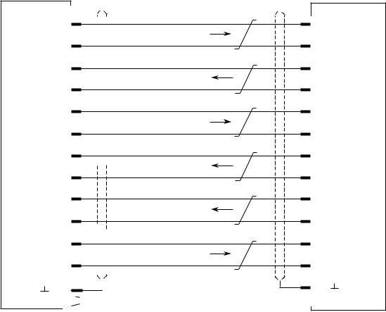
3.2Polarity and voltage level assignment of the RS 422 interface
V |
|
|
|
5 V |
|
|
|
|
Logical ºHº |
|
|
2.5 V |
|
|
|
|
Vmin. |
Vmax. |
|
|
=2V |
=5V |
|
0.5 V |
Logical ºLº |
|
|
0 V |
t |
||
|
|||
|
|
V
Output Y
VOH 2.5 V
1.5 V |
|
|
|
|
|
|
|
|
|
|
|
|
|
|
|
|
|
|
|
|
|
|
|
|
|
|
|
|
|
|
|
|
|
|
|
|
|
|
|
|
|
|
|
|
Vmin. |
|
|
|
|
|
|
|
|
|
|
|
|
|
|
|
|
|
|
|
|
|
|
|
|
|
|
|
|
|
|
|
|
|
|
|
|
|
|
|
|
|
|
|
|
||
|
|
|
|
|
|
|
|
|
|
|
|
|
|
|
|
|
|
|
|
|
|||||||||||||||||||||||||
|
|
|
|
|
|
|
|
|
|
|
|
|
|
|
|
|
|
|
|
|
|
|
|
|
|
|
|
|
|
|
|
|
|
|
|
|
|
|
|
|
|
|
|
|
=2V |
VOL 0.5 V
Output Z
t
The voltage levels refer to the reference voltage of the driver circuit AM 26 LS 31. The voltage between the differential lines is
Vmin |
= |
2 V |
Vmax |
= |
5 V |
3-2 |
© Siemens AG 1990 All Rights Reserved 6ZB5 410-0AQ02 |
|
SINUMERIK System 800, (PJ) |
10.88 |
3 RS 422 Interface |
3.3.1 RS 422 drivers
3.3RS 422 drivers and receivers
3.3.1RS 422 drivers
The RS 422 output signals are generated from the TTL signals of the USART 8251 via the AM 26 LS 31 line drivers.
|
|
|
|
TTL level |
|
|
|
|
|
|
|
|
|
Data of the AM 26 LS 31 circuit |
|
|
|
|
|
|
|
|
Supply voltage |
Vcc |
= |
5 V |
|
|
|
|
|
||||
AM 26 LS 31 |
|
|
|
|
Max. output voltage |
VoL |
= |
0.5 V |
|
|
|
|
|
Min. output voltage |
VoH |
= |
2.5 V |
|
|
|
|
|
||||
|
|
|
|
|
Differential voltage |
2 |
... |
5 V |
|
|
|
|
|
|
|
|
|
RS 422 level
ZY
3.3.2RS 422 receivers
The RS 422 input signals are converted to TTL signals via the AM 26 LS 33 line receivers.
|
|
|
150 |
|
|
|
|
|
Data of the AM 26 LS 33 circuit |
||||||
|
|
|
|
||||||||||||
|
|
|
|
|
|
|
|
|
|
|
|
|
|
||
|
|
|
|
|
|
|
|
|
|
|
|
|
|
||
|
|
|
|
|
|
|
|
|
|
|
|
|
|
RS 422 level |
Vcc = 5 V |
|
|
|
|
|
|
|
|
|
|
|
|
|
|
||
|
|
|
|
|
|
|
|
|
|
|
|
|
|
Supply voltage |
|
|
|
|
|
|
|
|
|
|
|
|
|
|
|
Input parallel |
|
|
|
|
|
|
|
|
|
|
|
|
|
|
|
|
|
AM 26 LS 33 |
|
|
|
|
|
|
|
|
|
|
|
|
resistance |
150 Ohm |
|
|
|
|
|
|
|
|
|
|
|
|
|
||||
|
|
|
|
|
|
|
|
|
|
|
|
|
|
Differential operation |
|
|
|
|
|
|
|
|
|
|
|
|
|
|
|
|
|
|
|
|
|
|
|
|
|
|
|
|
|
|
|
voltage |
2 ... 5 V |
|
|
|
|
|
|
|
|
|
|
|
|
|
|
|
|
TTL level
© Siemens AG 1990 |
All Rights Reserved 6ZB5 410-0AQ02 |
3-3 |
SINUMERIK System |
800, (PJ) |
|
3 RS 422 Interface |
07.90 |
3.4 Interface link to I/O device for RS 422
3.4Interface link to I/O device for RS 422
SINUMERIK |
|
|
|
|
|
I/O device |
|
DTE |
DCE |
|
DTE |
|
|
|
|
|
* T x D |
|
|
T x D |
|
|
* R x D |
|
|
R x D |
|
R |
|
|
S |
RTS |
|
|
||
4 |
|
|
2 |
* RTS |
|
2 |
||
|
||
s |
CTS |
|
i |
||
|
||
g |
|
|
n |
* CTS |
|
a |
||
|
||
l |
|
sDSR
*DSR
DTR
*DTR
2 |
|
|
Transmitted data |
|
O |
|
|
||
|
|
D1 |
(103) |
|
|
|
|||
|
|
|||
15 |
|
|
||
|
|
|
|
|
|
|
|
|
|
|
|
|
|
|
O |
|
|
|
|
|
|
|
|
|
|
|
|
|
|
|
|
|
|
|
3 |
|
|
Received data |
|
|
|
|||
|
|
|||
|
|
|||
O |
|
|
||
|
|
|||
|
|
D2 |
(104) |
|
16 |
|
|
||
|
|
|||
|
|
|
|
|
|
|
|
|
|
|
|
|
|
|
O |
|
|
|
|
|
|
|
|
|
|
|
|
|
|
|
|
|
|
|
4 |
|
|
Request to send |
|
|
|
|||
|
|
|||
|
|
|||
O |
|
|
||
|
|
|||
|
|
S2 |
(105) |
|
|
|
|||
17 |
|
|
||
|
|
|
|
|
|
|
|
|
|
|
|
|
|
|
O |
|
|
|
|
|
|
|
|
|
|
|
|
|
|
|
|
|
|
|
5 |
|
|
Clear to send |
|
|
|
|||
|
|
|||
|
|
|||
O |
|
|
||
|
|
|||
|
|
M2 |
(106) |
|
|
|
|||
|
|
|
||
18
O
6 |
Data set ready |
||
O |
|||
M1 |
(107) |
||
19 |
|
|
|
O |
|
|
|
|
20 |
|
|
|
|
|
Data terminal ready |
||
|
|
|
|
|
|
||||
|
|
|
|
|
|
||||
|
|
|
|
|
|
||||
O |
|
|
|
|
|
||||
|
|
|
|
|
|||||
|
|
|
|
|
S1.2 |
(108.2) |
|||
|
|
|
|
|
|||||
8 |
|
|
|
|
|
|
|||
|
|
|
|
|
|
|
|
||
|
|
|
|
|
|
|
|
||
|
|
|
|
|
|
|
|
||
O |
|
|
|
|
|
|
|
||
|
|
|
|
|
|
|
|||
|
|
|
|
|
|
|
|||
|
|
|
|
|
|
|
|||
|
1 |
|
|
|
|
|
|
|
|
|
|
|
|
|
|
|
|
|
|
|
|
|
|
|
|
|
|
|
|
O |
|
|
|
|
Protective ground |
||||
|
|
|
|
|
|
|
E1 |
(101) |
|
|
|
|
|
|
|
|
|
||
|
|
|
|
|
|||||
3 |
|
O |
* R x D |
16 |
|
O |
R x D |
2 |
|
O |
* T x D |
15 |
|
O |
T x D |
5 |
|
O |
CTS |
18 |
|
O |
* CTS |
4 |
|
O |
RTS |
17 |
|
O |
* RTS |
20 |
|
O |
DTS |
8 |
|
O |
* DTR |
6 |
|
O |
DSR |
19 |
|
O |
* DSR |
1 |
|
O |
|
In all signal names and directions, the SINUMERIK is taken to be a DTE.
Which of the control and message lines are used will depend on the I/O device. The specification I/O device peripheral unit determines how it is connected.
In the interface link diagram, a device is assumed to comply with the SINUMERIK specification. The RS 422 interface is on a special connector.
3.5Length of the transmission line
The maximum cable length for RS 422 transmission is 1 km.
3.6Level conversion from V.24 to RS 422
With the SINUMERIK System 800 the V.24 level of the V.24 interfaces can be converted into a RS 422 level with a special cable. The converter electronics are integrated into the specific SINUMERIK cable connector (housing of fibre glass conductor).
The adjustable interfaces are listed in Section 7.1 corresponding to the controls.
END OF SECTION
3-4 |
© Siemens AG 1990 All Rights Reserved 6ZB5 410-0AQ02 |
SINUMERIK System 800, (PJ)
10.88 |
4 Interface Overview |
4.1 Pin assignments of the data interfaces
4 Interface Overview
4.1Pin assignments of the data interfaces
4.1.1Pin assignments on the V.24/20 mA universal interface
D-Sub, 25-pin, socket on SINUMERIK.
Pin |
Signal name |
Interface |
Signal name to |
DIN 66020 |
|
||||
|
SINUMERIK |
assignment |
|
VDI 2880 |
|
||||
|
|
|
|
|
|
(English from CCITT recommendation) |
|||
|
|
|
|
|
|
(referring to SINUMERIK as a DTE) |
|||
1 |
|
|
|
|
|
Protective ground |
|
E1 |
(101) |
|
|
|
|
|
|
||||
|
|
|
|
|
|
||||
2 |
*TxD |
V.24 |
Transmitted data |
|
D1 |
(103) |
|||
3 |
*RxD |
V.24 |
Received data |
|
D2 |
(104) |
|||
4 |
RTS |
V.24 |
Request to send |
|
S2 |
(105) |
|||
5 |
CTS |
V.24 |
Clear to send |
|
M2 |
(106) |
|||
6 |
DSR |
V.24 |
Data set ready |
|
M1 |
(107) |
|||
7 |
MEXT |
V.24 |
Signal ground |
|
E2 |
(102) |
|||
8 |
|
|
|
|
|
|
|
|
|
9 |
|
|
|
|
|
|
|
|
|
10 |
TTY2 |
20 mA |
Transmitted data+ |
|
|
|
|||
11 |
|
|
|
|
|
|
|
|
|
12 |
T 20 mA |
20 mA |
Transmit source |
|
|
|
|||
13 |
TTY4 |
20 mA |
Received data + |
|
|
|
|||
14 |
TTY3 |
20 mA |
Received data ± |
|
|
|
|||
15 |
|
|
|
|
|
|
|
|
|
16 |
R 20 mA |
20 mA |
Receive source |
|
|
|
|||
17 |
|
|
|
|
|
|
|
|
|
18 |
|
|
|
|
|
|
|
|
|
19 |
TTY1 |
20 mA |
Transmitted data ± |
|
|
|
|||
20 |
DTR |
V.24 |
Data terminal ready |
S1.2 |
(108.2) |
||||
21 |
0V (T) |
20 mA |
Current return |
|
|
|
|||
22 |
|
|
|
|
|
|
|
|
|
23 |
|
|
|
|
|
|
|
|
|
24 |
0V (R) |
20 mA |
Current return |
|
|
|
|||
25 |
|
|
|
|
|
|
|
|
|
|
|
|
|
|
|
|
|
|
|
© Siemens AG 1990 All Rights Reserved 6ZB5 410-0AQ02 |
4-1 |
SINUMERIK System 800, (PJ)
4 Interface Overview |
10.88 |
4.1.2 Pin assignments of the RS 422 interface
4.1.2Pin assignments of the RS 422 interface
D-Sub, 25-pin, socket on SINUMERIK
Pin |
Signal name |
Interface |
Signal name to DIN 66020 |
|
|
||||
|
SINUMERIK |
assignment |
(English from CCITT recommendation) |
||||||
|
|
|
|
|
|
(referring to SINUMERIK as a DTE) |
|||
|
|
|
|
|
|
|
|
|
|
1 |
|
|
|
|
|
Protective ground |
E1 |
(101) |
|
|
|
|
|
|
|
||||
|
|
|
|
|
|
||||
2 |
*TxD |
RS 422 |
Transmitted data |
D1 |
(103) |
|
|||
3 |
*RxD |
RS 422 |
Received data |
D2 |
(104) |
|
|||
4 |
RTS |
RS 422 |
Request to send |
S2 |
(105) |
|
|||
5 |
CTS |
RS 422 |
Clear to send |
M2 |
(106) |
|
|||
6 |
DSR |
RS 422 |
Data set ready |
M1 |
(107) |
|
|||
7 |
|
|
|
|
|
|
|
|
|
8 |
*DTR |
RS 422 |
Data terminal ready |
S1.2 (108.2) |
|||||
9 |
|
|
|
|
|
|
|
|
|
10 |
|
|
|
|
|
|
|
|
|
11 |
|
|
|
|
|
|
|
|
|
12 |
|
|
|
|
|
|
|
|
|
13 |
|
|
|
|
|
|
|
|
|
14 |
|
|
|
|
|
|
|
|
|
15 |
TxD |
RS 422 |
Transmitted data |
D1 |
(103) |
|
|||
16 |
RxD |
RS 422 |
Received data |
D2 |
(104) |
|
|||
17 |
*RTS |
RS 422 |
Request to send |
S2 |
(105) |
|
|||
18 |
*CTS |
RS 422 |
Clear to send |
M2 |
(106) |
|
|||
19 |
*DSR |
RS 422 |
Data set ready |
M1 |
(107) |
|
|||
20 |
DTR |
RS 422 |
Data terminal ready |
S1.2 (108.2) |
|||||
21 |
|
|
|
|
|
|
|
|
|
22 |
|
|
|
|
|
|
|
|
|
23 |
|
|
|
|
|
|
|
|
|
24 |
|
|
|
|
|
|
|
|
|
25 |
|
|
|
|
|
|
|
|
|
|
|
|
|
|
|
|
|
|
|
4-2 |
© Siemens AG 1990 All Rights Reserved 6ZB5 410-0AQ02 |
|
SINUMERIK System 800, (PJ) |

07.90 |
4 Interface Overview |
4.2 Explanation of signal names
4.2Explanation of signal names
CTS |
Clear to Send |
DSR |
Data Set Ready |
DTR |
Data Terminal Ready |
MEXT |
External Ground |
RTS |
Request to Send |
RxD |
Receive Data V.24 |
R20mA |
Receive Source 20 mA |
TxD |
Transmit Data V.24 |
TTY1 |
Teletype (± 20 mA) Transmit Data |
TTY2 |
Teletype (+20 mA) Transmit Data |
TTY3 |
Teletype (± 20 mA) Receive Data |
TTY4 |
Teletype (+20 mA) Receive Data |
T20mA |
Transmit Source 20 mA |
0V(R) |
0V ± Receive 20 mA |
0V(T) |
0V ± Transmit 20 mA |
4.3Format of a serially transmitted character
|
|
|
|
|
|
|
|
|
|
|
|
|
|
|
|
|
|
|
|
|
|
|
|
|
T x D |
Quiescent |
|
|
|
|
|
|
|
|
|
Data |
|
bits |
|
|
|
|
|
|
|
|
Stop |
|
|
|
|
|
|
|
|
|
|
|
|
|
|
|
|
|
|
|||||||||
state |
|
|
|
|
|
|
|
|
|
|
|
|
|
|
|
|
|
|
elements |
|
||||
R x D |
|
|
|
|
1 |
|
2 |
|
4 |
|
5 |
|
6 |
|
7 |
|
8 |
|
|
|
||||
|
|
|
|
|
3 |
|
|
|
|
|
|
|
||||||||||||
|
|
|
|
|
|
|
|
|
|
|
||||||||||||||
|
|
|
|
Start |
|
|
|
|
|
|
|
|
|
|
|
|
|
Parity |
|
|||||
|
|
|
|
element |
|
|
|
|
|
|
|
|
|
|
|
|
|
bit (optional) |
|
|||||
|
|
|
|
|
|
|
|
|
|
|
|
|
|
|
|
|
|
|
|
|
|
|
|
|
In the SINUMERIK universal interface the 8th bit of a character, which is normally the parity bit, is designated as 8th data bit.
The parity bit is an optional 9th bit added to an ASCII character on even, and to an EIA character on odd bit combinations. The 8th bit is always part of the data.
An additional parity bit (9th. bit) may be generated via setting data if desired for adaptation to certain I/O devices.
© Siemens AG 1990 All Rights Reserved 6ZB5 410-0AQ02 |
4-3 |
SINUMERIK System 800, (PJ)
4 Interface Overview |
10.88 |
4.4 Block diagrams of the data interfaces
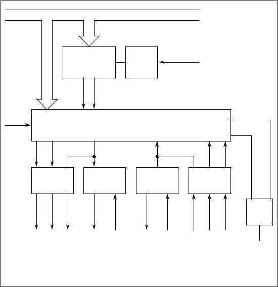
4.4Block diagrams of the data interfaces
4.4.1Block diagram of V.24/20 mA universal interface
Data bus DB |
|
|
|
|
|
|
|
|
||
|
|
Baud rate |
|
Scaler |
CPU frequency |
|
|
|
||
|
|
generator |
|
|
|
|
|
|
||
|
|
|
|
|
|
|
|
|
||
|
|
T x C |
R x C |
|
|
|
|
|
|
|
Select (1) |
|
|
|
|
|
|
|
|
|
|
|
|
|
|
U SART 1) |
|
|
|
|
|
|
|
|
|
T x D |
|
|
R x D |
|
|
|
|
RTS |
DTR |
|
|
|
|
|
CTS |
DSR |
|
|
|
|
|
|
|
|
|
|
|
||
|
V.24 |
|
20 mA |
|
20 mA |
|
V.24 |
|
|
|
|
driver |
|
driver |
|
receiver |
|
receiver |
|
|
|
|
|
|
|
|
|
|
|
|
T x RDY |
R x RDY |
|
|
|
|
|
|
|
|
|
|
1 |
RTS |
DTR |
* T x D |
TTY 2 |
TTY 1 |
TTY 4 |
TTY 3 |
* R x D |
CTS |
DSR |
|
|
|
|
|
|
|
|
|
|
|
IR |
|
V.24 |
|
20 mA |
Duplex |
V.24 |
|
Interrupt |
|||
|
|
|
|
|||||||
|
Output |
|
Transmit |
Receive |
Input |
|
|
|||
1) USART = Universal Synchronous Asynchronous Receiver Transmitter Its tasks are:
·Conversion of 8 bits parallel to 8 bits serial
·Transmitting and receiving at different baud rates (possibly simultaneously)
·Error detection
·Define and check parity
4-4 |
© Siemens AG 1990 All Rights Reserved 6ZB5 410-0AQ02 |
SINUMERIK System 800, (PJ)
07.90 |
4 Interface Overview |
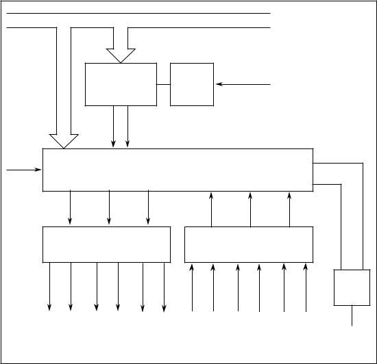
4.4.2 Block diagram of an RS 422 interface
4.4.2 Block diagram of an RS 422 interface
Data bus DB |
|
|
|
|
|
|
|
|
|
||
|
|
Baud rate |
|
|
Scaler |
|
CPU frequency |
|
|||
|
|
generator |
|
|
|
|
|
|
|
||
|
|
|
|
|
|
|
|
|
|
||
|
|
T x C |
|
R x C |
|
|
|
|
|
|
|
Select (1) |
|
|
|
|
|
|
|
|
|
|
|
|
|
|
|
|
U SART |
|
|
|
|
|
|
|
RTS |
DTR |
|
T x D |
|
R x D |
|
CTS |
|
DSR |
|
|
|
RS 422 |
|
|
|
|
RS 422 |
|
|
||
|
|
driver |
|
|
|
|
receiver |
|
|
||
|
|
|
|
|
|
|
|
|
|
|
1 |
RTS |
* RTS |
DTR |
* DTR |
* Tx D |
Tx D |
* R x D |
R x D |
CTS |
* CTS |
DSR |
*DSR |
|
|
|
|
|
|
|
|
|
|
|
IR |
|
|
RS 422 Output |
|
|
|
RS 422 Input |
|
Interrupt |
|||
|
|
|
|
|
|
|
|||||
END OF SECTION
© Siemens AG 1990 |
All Rights Reserved 6ZB5 410-0AQ02 |
4-5 |
SINUMERIK System |
800, (PJ) |
|
10.88 |
5 Adapting the Interfaces to I/O Devices |
5.1 General notes
5 Adapting the Interfaces to I/O Devices
5.1General notes
Peripheral devices are subdivided according to the type of data transmission:
·Line-controlled devices:
±Control via the control lines DSR, DTR, CTS, RTS
·Uncontrolled devices:
±Asynchronous transmission without control
·Character-controlled devices:
±Control using control characters on the data lines
Each interface and data direction is defined at the SINUMERIK end for the I/O device using setting data (see selection tables). The control lines are activated by connecting them.
On startup the default values of the machine data and setting data adapt the interface to the Siemens PT 80 page printer (universal device).
© Siemens AG 1990 All Rights Reserved 6ZB5 410-0AQ02 |
5-1 |
SINUMERIK System 800, (PJ)

5 Adapting the Interfaces to I/O Devices |
03.91 |
5.2 Setting data
5.2Setting data
SINUMERIK System 800 has one set of 8 bytes per interface for adapting the I/O devices. The input and output directions are set separately.
The setting of the EIA code for special characters º@º, º:º, º=º, º[º, º]º and º,º and the definition for the character ºEnd of transmissionº is entered in 7 additional bytes for two interfaces.
|
|
Byte |
|
|
|
|
|
|
|
Function |
|
|
|
|
|
|
|
|
||||
|
|
No. |
|
|
|
|
|
|
|
Bit |
|
|
|
|
|
|
|
|
|
|
|
|
|
|
7 |
|
6 |
|
5 |
|
4 |
|
3 |
|
2 |
|
1 |
|
0 |
|
|
||||
|
|
|
|
|
|
|
|
|
|
|
|
|
|
|
|
|
|
|
|
|
||
|
1 |
|
|
|
|
Device coding - input- |
|
|
|
|
|
|
|
|
||||||||
|
|
|
|
|
|
|
|
|
|
|
|
|
|
|
|
|
|
|
|
|||
|
2 |
|
|
|
|
Transmission format - input - |
|
|
|
|
|
|||||||||||
|
|
|
|
|
|
|
|
|
|
|
|
|
|
|
|
|
|
|
|
|
|
|
|
|
|
Stop elements |
Type of |
|
Parity |
|
|
|
Baud rate |
|
|
|
|||||||||
|
|
|
parity |
|
bit |
|
|
|
|
|
|
|
||||||||||
|
|
|
|
|
|
|
|
|
|
|
|
|
|
|
|
|
|
|
||||
|
3 |
|
|
|
|
Device coding - output - |
|
|
|
|
|
|
|
|
||||||||
|
|
|
|
|
|
|
|
|
|
|
|
|||||||||||
|
|
4 |
|
|
|
|
Transmission format - output - |
|
|
|
|
|
||||||||||
|
|
|
|
|
|
|
|
|
|
|
|
|
|
|
|
|
|
|||||
|
|
|
Stop elements |
Type of |
|
Parity |
|
|
Baud rate |
|
|
|
||||||||||
|
|
|
parity |
|
bit |
|
|
|
|
|
|
|
||||||||||
|
|
|
|
|
|
|
|
|
|
|
|
|
|
|
|
|
|
|
||||
|
|
|
|
|
|
|
|
|
|
|
|
|
|
|||||||||
|
|
5 |
|
|
|
|
Xon character (e.g. DC1 = 11hex) |
|
|
|
|
|
||||||||||
|
|
|
|
|
|
|
|
|
|
|
|
|
|
|
|
|||||||
|
|
6 |
|
|
|
|
Xoff character (e.g. DC3 = 93hex) |
|
|
|
|
|
||||||||||
|
|
|
|
|
|
|
|
|
|
|
|
|
|
|
|
|
|
|
|
|||
|
|
7 |
|
|
|
|
|
|
|
Special bits |
|
|
|
|
|
|
|
|
||||
|
|
|
|
|
|
|
|
|
|
|
|
|
|
|
|
|
|
|
|
|||
|
|
|
Output |
|
Program |
|
End of |
|
Output in |
|
Stop at |
|
Evaluate |
|
Output |
|
Read-in |
|
|
|||
|
|
|
without |
|
start |
|
block |
|
|
EIA |
|
character |
|
data set |
|
without |
|
progr. of |
|
|||
|
|
|
1st Xon |
|
with LF |
|
CR LF |
|
|
code |
|
end of |
|
ready |
|
leader |
|
systems |
|
|||
|
|
|
character |
|
|
|
|
|
|
|
|
trans- |
|
DSR |
|
and |
|
3, 8 |
|
|
||
|
|
|
|
|
|
|
|
|
|
|
|
mission |
|
|
|
|
trailer |
|
|
|
|
|
|
|
|
|
|
|
|
|
|
|
|
|
|
|
|
|
|
|
Delete |
|
Switch off |
|
|
|
|
8 |
|
|
|
|
|
|
|
|
|
|
|
|
|
|
|
|
|
|
||
|
|
|
|
|
|
|
|
|
|
|
|
|
|
|
|
program |
|
time |
|
|
||
|
|
|
|
|
|
|
|
|
|
|
|
|
|
|
|
|
|
|
|
|||
|
|
|
|
|
|
|
|
|
|
|
|
|
|
|
|
|
|
without |
|
watchdog |
|
|
|
|
|
|
|
|
|
|
|
|
|
|
|
|
|
|
|
|
reorgan. |
|
|
|
|
|
|
|
|
|
|
EIA code for º@º (e.g. 6D hex) |
|
|
|
|
|
|||||||||||
|
|
9 |
|
|
|
|
|
|
|
|
|
|||||||||||
|
|
|
|
|
|
|
|
|
|
|
|
|
|
|
||||||||
|
|
10 |
|
|
|
|
EIA code for º:º (e.g. 46 hex) |
|
|
|
|
|
|
|
|
|||||||
|
|
|
|
|
|
|
|
|||||||||||||||
|
|
11 |
|
|
Code for ºEnd of transmissionº (e.g. ETX=03 hex in ISO) |
|
|
|
||||||||||||||
|
|
|
|
|
|
|
|
|
|
|
|
|||||||||||
|
|
12 |
|
|
|
|
EIA Code for º=º (e.g. 1C Hex) |
|
|
|
|
|
||||||||||
|
|
|
|
|
|
|
|
|
|
|
|
|
|
|
|
|
||||||
|
|
13 |
|
|
|
|
|
|
EIA code for º[º |
|
|
|
|
|
|
|
|
|||||
|
|
|
|
|
|
|
|
|
|
|
|
|
|
|
|
|
|
|
|
|
|
|
|
|
14 |
|
|
|
|
|
|
EIA code for º]º |
|
|
|
|
|
|
|
|
|||||
|
|
|
|
|
|
|
|
|
|
|
|
|
|
|
|
|
||||||
|
|
|
|
|
|
|
|
|
|
|
|
|
|
|
|
|
|
|
|
|
|
|
|
|
15 |
|
|
|
|
|
|
EIA code for º,º |
|
|
|
|
|
|
|
|
|||||
|
|
|
|
|
|
|
|
|
|
|
|
|
|
|
|
|
||||||
|
|
|
|
|
|
|
|
|
|
|
|
|
|
|
|
|
|
|
|
|
||
5-2 |
|
|
|
|
|
|
|
© Siemens AG 1990 All Rights Reserved 6ZB5 410-0AQ02 |
||||||||||||||
|
|
|
|
|
|
|
|
|
|
|
|
|
|
|
|
SINUMERIK System 800, (PJ) |
||||||
 Loading...