


Start-Up 11/2005 Edition
sinumerik
SIEMENS
SINUMERIK 801

SINUMERIK 801 Document Structure
User Documentation: Operation and Programming
Turning
Technical Documentation: Start-Up
Turning
User Documentation: Diagnostics Guide
Turning

SINUMERIK 801 |
|
|
|
|
||||
|
|
|
SINUMERIK 801 Control System |
1 |
||||
|
|
|
|
|
|
|
|
|
Start-Up |
Installation and Start-Up |
2 |
|
|||||
Built-In PLC Application |
3 |
|||||||
|
|
|
||||||
|
|
|
|
|
|
|
||
|
|
|
Setting Up |
4 |
||||
Technical Manual |
|
5 |
|
|
||||
|
|
|
Services, Diagnosis & Data |
|
|
|||
|
|
|
Saving |
|
|
|
|
|
|
|
|
|
|
|
|
|
|
|
|
|
Accessories |
6 |
|
|||
|
|
|
|
|
|
|
|
|
|
|
|
Technical Appendix |
7 |
|
|
||
|
|
|
|
|
|
|
|
|
Valid for
Control system
SINUMERIK 801
11. 2005 Edition

SINUMERIK ® Documentation
Key to editions
The editions listed below have been published prior to the current edition.
The column headed “Note” lists the amended sections, with reference to the previous edition.
Marking of edition in the “Note” column:
A ... ... |
New documentation. |
B ... ... |
Unchanged reprint with new order number. |
C ... ... |
Revised edition of new issue. |
Edition |
Order No. |
Note |
2005.11 |
A5E00702069 |
A |
Trademarks
SIMATIC®, SIMATIC HMI®, SIMATIC NET®, SIMODRIVE®, SINUMERIK®, and SIMOTION® are registered trademarks of SIEMENS AG.
Other names in this publication might be trademarks whose use by a third party for his own purposes may violate the registered holder.
Copyright Siemens AG 2005. All right reserved
The reproduction, transmission or use of this document or its contents is not permitted without express written authority. Offenders will be liable for damages. All rights, including rights created by patent grant or registration of a utility model, are reserved.
Exclusion of liability
We have checked that the contents of this document correspond to the hardware and software described. Nonetheless, differences might exist and we cannot therefore guarantee that they are completely identical. The information contained in this document is reviewed regularly and any necessary changes will be included in the next edition. We welcome suggestions for improvement.
© Siemens AG, 2005
Subject to technical changes without notice.
Siemens-Aktiengesellschaft. |
SINUMERIK 801 |

Safety notices
!
!
!
Qualified person
This Manual contains notices intended to ensure your personal safety, as well as to protect products and connected equipment against damage. Safety notices are highlighted by a warning triangle and presented in the following categories depending on the degree of risk involved:
Danger
Indicates an imminently hazardous situation which, if not avoided, will result in death or serious injury or in substantial property damage.
Warning
Indicates a potentially hazardous situation which, if not avoided, could result in death or serious injury or in substantial property damage.
Caution
Used with safety alert symbol indicates a potentially hazardous situation which, if not avoided, may result in minor or moderate injury or in property damage.
Caution
Used without safety alert symbol indicates a potentially hazardous situation which, if not avoided, may result in property damage.
Notice
Indicates important information relating to the product or highlights part of the documentation for special attention.
The unit may only be started up and operated by qualified person or persons. Qualified personnel as referred to in the safety notices provided in this document are those who are authorized to start up, earth and label units, systems and circuits in accordance with relevant safety standards.
Proper use
!
Please observe the following:
Warning
The unit may be used only for the applications described in the catalog or the technical description, and only in combination with the equipment, components and devices of other manufacturers as far as this is recommended or permitted by Siemens.
This product must be transported, stored and installed as intended, and maintained and operated with care to ensure that it functions correctly and safely.
SINUMERIK 801 |
I |
Start-Up |
|

Table of Contents
Table of Contents
1.SINUMERIK 801 Control System…………………………………………………………………………… 1-1
1.1 |
System Overview |
…………………………………………………… 1-1 |
1.2 |
CNC Operator Panel |
……………………………………………… ………… 1-3 |
1.3Position of the Interfaces………………………………………………………………………………… 1-5
1.4 Technical Data |
………………………………………………………………………………… 1-6 |
2.Installation and Start-Up ………………………………………………………………………… 2-1
2.1 |
Cabinet, Power Supply and Grounding |
…………………………………………………… … 2-1 |
2.2 |
Installing and Cabling ……………………………………………………………………………… 2-4 |
|
2.2.1 |
Installing the control system ……………………………………………………………………… 2-4 |
|
2.2.2Cabling …………………………………………………………………………………………… 2-11
2.2.2.1 |
Connecting with the stepper drives ………………………………………………………………… |
2-11 |
|
2.2.2.2 |
Connecting with the servo drives (example) ……………………………………………………… |
2-12 |
|
2.3 |
Interfaces and Cables ……………………………………………………………………………… |
2-15 |
|
2.3.1 |
Power supply for CNC – X1 |
……………………………………………………………… |
2-16 |
2.3.2 |
RS232 interface - X2 (RS232) …………………………………………………………… |
2-16 |
|
2.3.3 |
Spindle encoder interface - X3 (SPINDLE)…………………………………………………… |
2-17 |
|
2.3.4Feed drive interface – X4 (AXIS)…………………………………………………………………… 2-18
2.3.5 Handwheel & extension keys connection - X10 (MPG) ……………………………………… 2-19
2.3.6BERO input interface - X20 (BERO)…………………………………………………………………… 2-19
2.3.7 |
Digital inputs/outputs - X100 (DIN0) & X101 (DIN1), X200 (DOUT0) & X201 (DOUT1)… |
2-20 |
|
2.3.8 |
Connecting cables for SINUMERIK 801 ……………………………………………………… |
2-22 |
|
2.4 |
Installing and Starting-Up the Drive Modules |
…………………………………………… |
2-26 |
2.4.1 |
Connecting the STEPDRIVE C/C+ drive modules ………… …………………………………… |
2-26 |
|
2.4.2 |
Connecting the servo drive modules |
………… …………………………………… |
2-26 |
3.Built-In PLC Application …………………………………………………………………………………… 3-1
3.1 |
Input/Output Configuration |
…………………………………………………………………… |
3-4 |
|
3.2 |
Definition of User Keys |
|
………………………………………………………………… |
3-6 |
3.3 |
PLC Machine Data |
……………………………………………………………………………… |
3-9 |
|
3.4Fixed PLC Alarms………………………………………………………………………………………… 3-16
4. Setting Up |
…………………………………………………………………………………… |
4-1 |
|||
4.1 |
Setting Up NC Parameters |
………………………………………………………………… |
4-6 |
||
4.2 |
Starting Up the Dynamic Characteristic of the Axes ……………………………………………… |
4-9 |
|||
4.3 |
Starting Up Reference Points |
……………………………………………………………… |
4-9 |
||
4.4 |
Software Limit Switch and Backlash Compensation…………………………………………… |
4-14 |
|||
4.5 |
Rotation Monitoring |
………………………………………………………………………… |
4-16 |
||
4.6 |
Leadscrew Error Compensation |
…………………………………………………………… |
4-17 |
||
4.7 |
Starting Up the Spindle |
……………………………………………………………………… |
4-17 |
||
5. Services, Diagnosis & Data Saving |
………………………………………………………… |
5-1 |
|||
5.1 |
Services |
…………………………………………………………………………………………… |
5-2 |
||
5.2Diagnosis …………………………………………………………………………………………… 5-2
5.3Data Saving …………………………………………………………………………………………… 5-6
5.3.1Internal data saving …………………………………………………………………………………… 5-6
5.3.2External data saving …………………………………………………………………………………… 5-6
5.3.3 Important Notice …………………………………………………………………………………… 5-9
6.Accessories ……………………………………………………………………………… 6-1
7.Techncial Appendix …………………………………………………………………………………………7-1 7.1 List of Machine Data ………………………………………………………………………………………7-1
SINUMERIK 801 |
III |
Start-Up |
|
SINUMERIK 801 Control System 1
1.1System Overview
General |
The SINUMERIK 801 is a highly integrated, high-performance |
and |
|
economic numerical control system, which can be extensively applied |
to |
economic CNC turning machines. It can control 2 feed axes and 1 spindle. Control signals output to feed axes include digital pulse, direction and enable signals, control signals output to the spindle include analog voltage and enable. The SINUMERIK 801 can thus be used to control feed axes for stepper drives, and servo drives with digital pulse interfaces. Either servo spindle or variable frequency spindle can be controlled via the SINUMERIK 801. This documentation gives descriptions for configuring the SINUMERIK 801 with stepper drives/servo drives.
System components The SINUMERIK 801 control system is a compact CNC unit. It consists of the following components:
hCNC
A compact CNC with an integrated 6″ LCD, full NC keys and MCP area;
hStepper drives and stepper motors
1)Stepper drives STEPDRIVE C/C+;
2)Five-phase hybrid stepper motors
hCables
1)Signal cables for connecting CNC to drives;
2)Cables for connecting drives to motors;
3)Signal cable for connecting spindle encoder to CNC;
4)RS232 cable for connecting CNC to a PC;
5)Signal cable for connecting CNC to an electronic handwheel.
zOne spindle encoder
zOne electronic handwheel
zPossible configurations by users: servo motors (with digital pulse interfaces) and servo motors.
SINUMERIK 801 |
1-1 |
Start-Up |
|

SINUMERIK 801 Control System
SINUMERIK 801 system
Fig.1-1 SINUMERIK 801 system overview CNC + stepper drives + stepper motors
1-2 |
SINUMERIK 801 |
|
Start-Up |
SINUMERIK 801 Control System
1.2CNC Operator Panel
Layout of the CNC operator panel
The SINUMERIK 801 has a compact operator panel, which can be divided into three areas as: LCD, NC keys and MCP area.
LCD
NC keys
MCP area
Fig. 1-2 Layout of the CNC operator panel (front view)
Key definition
NC keyboard area |
|
Machine area key |
Cursor UP (with shift: page up) |
Recall key |
Cursor DOWN (with shift: page down) |
Softkey |
Cursor LEFT |
Area switchover key |
Cursor RIGHT |
ETC key |
Selection key/toggle key |
SINUMERIK 801 |
1-3 |
Start-Up |
|

SINUMERIK 801 Control System |
|
|
|
|
||||
|
|
|
|
Acknowledge alarm |
|
|
|
Delete key (backspace) |
|
|
|
|
|
||||
|
|
|
|
SPACE (INSERT) |
|
|
|
Vertical menu |
|
|
|
|
|
|
|
||
|
|
|
|
|
||||
|
|
|
|
ENTER / input key |
|
|
|
Shift key |
|
|
|
|
|
|
|
||
|
|
|
|
|
||||
|
|
|
|
Numerical keys (with shift for |
|
|
|
Alphanumeric keys (with shift for |
|
|
|
|
|
|
|
||
|
|
|
|
|
|
|
||
|
|
|
|
|
|
|
||
|
… |
|
alternative assignment) |
|
… |
|
alternative assignment) |
|
Notice
See”Operation & Programming” for the use of NC keys.
MCP (Machine Control Panel) area |
|
|
|
|
|
Chuck clamping (with LED) |
|
|
Spindle override 100 |
|
|
|
||
|
Chuck clamping internally / Chuck clamping |
|
|
Spindle override minus (with LED) |
|
|
|
||
|
|
|||
|
externally (with LED) |
|
|
|
|
Chuck unclamping (with LED) |
|
|
X axis, plus direction |
|
|
|||
|
Manual tool change (with LED) |
|
|
X axis, minus direction |
|
|
|
||
|
|
|||
|
Manual lubrication (with LED) |
|
|
Z axis, plus direction |
|
|
|
||
|
|
|||
|
Manual coolant (with LED) |
|
|
Z axis, minus direction |
|
|
|
||
|
|
|
||
|
AUTOMATIC (with LED) |
|
|
RAPID TRAVERSE OVERLAY |
|
|
|
||
|
|
|
||
|
SINGLE BLOCK (with LED) |
|
|
SPINDLE START LEFT |
|
|
|
||
|
|
|
||
|
|
|
|
Counterclockwise direction |
|
|
|
|
|
|
MANUAL DATA (with LED) |
|
|
SPINDLE STOP |
|
|
|
||
|
Increment (with LED) |
|
|
SPINDLE START RIGHT |
|
|
|
||
|
|
|
||
|
|
|
|
Clockwise direction |
1-4 |
|
|
|
|
|
|
|
SINUMERIK 801 |
|
|
|
|
|
Start-Up |

|
|
SINUMERIK 801 Control System |
JOG (with LED) |
|
RESET |
|
||
REFERENCE POINT (with LED) |
|
NC STOP |
|
||
|
||
Feedrate override plus (with LED) |
|
NC START |
|
||
|
||
Feedrate override 100 |
|
LED POK (Power OK), green |
|
||
Feedrate override minus (with LED) |
|
LED ERR (Error), red |
Spindle override plus (with LED) |
|
LED DIA (Diagnostics), yellow |
Emergency Stop button (option)
Notice
See Chapter 3 “Built-in PLC Application” for detailed definitions of User Keys, Traverse keys (+X, -X, +Z, -Z) and override keys.
SINUMERIK 801 |
1-5 |
Start-Up |
|
SINUMERIK 801 Control System
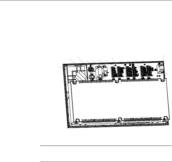
1.3Position of the Interfaces
General |
Interfaces of the control system are positioned in the rear of the CNC system, |
|
see Fig. 1-3 below. |
Interfaces |
Interfaces of the SINUMERIK 801 control system are shown as below: |
|
|
|
|
Fig. 1-3 Position of SINUMERIK 801 interfaces
Notice
See Section 2.3 “Interfaces and Cables” for detailed description of each interface.
1-6 |
SINUMERIK 801 |
|
Start-Up |

SINUMERIK 801 Control System
1.4Technical Data
Connected load |
Table 1–1 Connected load |
|
|
|
|
|
|
|
|
|
|
|
|
|
|
|
|
|
|
|
|
|
|
Parameter |
|
Min. |
Typ. |
|
Max. |
|
Unit |
|
|
|
Supply voltage |
20.4 |
24 |
|
28.8 |
|
V |
|
|
|
|
Ripple |
|
|
|
|
3.6 |
|
Vss |
|
|
|
Current consumption from 24 V |
|
|
2 |
|
|
|
A |
|
|
|
Power dissipation of CNC |
|
|
48 |
|
|
|
W |
|
|
|
Start-up current |
|
|
|
|
4 |
|
A |
|
|
|
Note: The 24V DC voltage must be |
generated as a functional extra-low voltage |
|||||||
|
with safe electrical isolation (to EN60204-1, Section 6.4, PELV). |
|
|
|||||||
Weight |
Table 1–2 Weight |
|
|
|
|
|
|
|
|
|
|
|
|
|
|
|
|
|
|||
|
|
Component |
|
|
Weight [g] |
|
|
|||
|
|
CNC |
|
|
2120 circa |
|
|
|||
Dimensions |
Table 1–3 Component dimensions |
|
|
|
|
|
|
|
|
|
|
|
|
|
|
|
|||||
|
|
Component |
|
Dimensions LxWxD [mm] |
||||||
|
|
CNC |
|
|
400 x 250 x 57.6 |
|
|
|||
Environmental operating conditions |
|
|
|
|
|
|
|
|
||
|
Table 1–4 Environmental operating conditions |
|
|
|
|
|
|
|||
|
|
|
|
|
|
|
|
|
|
|
|
|
Parameter |
|
|
|
|
|
|
|
|
|
|
Temperature range |
|
0….55°C (for box) |
|
|
|
|
||
|
|
(horizontal mounting and |
|
0….45°C (for display surface) |
|
|
||||
|
|
convection) |
|
|
|
|||||
|
|
|
|
|
|
|
|
|
|
|
|
|
Permissible relative humidity |
|
5…95% without condensation |
|
|
||||
|
|
Air pressure |
|
860 ... 1,060 hPa |
|
|
|
|
||
|
|
The operating conditions refer to EN60204-1. |
|
|
|
|
|
|
||
|
|
Installation in a housing (e.g. cubicle) is absolutely necessary for operation. |
||||||||
Transport and storage conditions |
|
|
|
|
|
|
|
|
||
|
Table 1–5 Transport and storage conditions |
|
|
|
|
|
|
|||
|
|
|
|
|
|
|
|
|
|
|
|
|
Parameter |
|
|
|
|
|
|
|
|
|
|
Temperature range |
|
-20 ... 60°C |
|
|
|
|
||
|
|
Permissible relative air humidity |
|
5 ... 95 % without condensation |
|
|||||
|
|
Air pressure |
|
700 ... 1,060hPa |
|
|
|
|
||
|
|
Transport height |
|
–1,000 ... 3,000m |
|
|
|
|
||
|
|
Free fall in transport package |
|
≤0.5m |
|
|
|
|
|
|
Protection class |
|
|
|
|
|
|
|
|
|
|
|
Class of protection I according to IEC 529 |
|
|
|
|
|
|
|||
|
The control must be equipped with a grounding conductor terminal. |
|
|
|||||||
|
Protection against ingress of solid foreign bodies and water according to ICE |
|||||||||
|
529: |
|
|
|
|
|
|
|
|
|
|
For CNC system: Front: IP54 Rear: IP20 |
|
|
|
|
|
|
|||
SINUMERIK 801 |
|
|
|
|
|
|
|
|
1-7 |
|
Start-Up |
|
|
|
|
|
|
|
|
|
|
Installation and Start-Up |
2 |
2.1Cabinet, Power supply and Grounding
Requirements for |
|
cabinet |
Machine tool builders need to pay attention to following requirements for a |
|
cabinet: |
1)Furnish the cabinet with a cooling or ventilation device; When using an electric fan to cool the cabinet, mount a dust gauze at the air inlet of the cabinet;
2)Mount all cabinet components on an unpainted galvanized metal plate;
3)Protection class for cabinet: IP54;
4)Grounding as per China national standard
GB/T5226.1-2002/IEC60204-1 2000 Safety of machinery - Electrical equipment of machines – Part II: General requirements;
5)In the case of poor field grounding, disconnect connections between PE and neutral (M24) of DC24V power supply and have CNC ungrounded;
6)When CNC is ungrounded, it’s imperative to configure a RS232 terminal adapter (order number: 6FX2003-0DS00) for RS232 connector to protect the connector from being broken down;
7)When wiring up the cabinet, AC supply lines (e.g. 85VAC, 220VAC, 380VAC lines and the cable for connecting an inverter to spindle motor) shall be routed separately from the 24VDC and signal cables;
8)If an inverter is used as spindle drive unit for the machine tool, take adequate anti-interference measures to protect the cabinet from mains interference and radio interference, etc;
9)Connect an isolation transformer (i.e. control transformer 380VAC ->220VAC, JBK3-400VA) to the 24VDC power supply for the control system; Connect a separate isolation transformer to the 85VAC power supply for stepper drives (i.e. drive transformer 380VAC ->85VAC, JBK3 series); Do not connect the primary side of both transformers to the same phase of the 380VAC;
10)Have the control transformer ungrounded in the case of poor field grounding, however, it’s required to connect the 220VAC power supply for either periphery (e.g. PC/PG) to the control transformer, see Fig. 2-1.
Control transformer |
Use a separate control |
transformer in the cabinet to supply the 24VDC |
|
power supply for CNC |
when Siemens stepper drives are used. Cable |
|
connections with the control transformer are shown in Fig. 2-1. |
|
SINUMERIK 801 |
|
2-1 |
|
|
|
Start-Up
U V W |
|
|
|
|
|
|
|
380VAC |
220VAC |
|
|
24V |
220VAC |
|
|
|
|
|
|
|
|||
|
|
|
|
L |
|
||
|
|
L |
L+ |
L+ |
|
||
|
|
220/24 DC |
|
|
|
||
1) |
|
|
Power |
CNC |
|
PC |
|
|
Supply |
0V |
|
|
|||
|
|
|
M |
M |
0V |
|
|
|
0V |
|
|
|
|
||
PE |
N |
PE |
PE |
N |
PE |
||
|
|||||||
4) |
3) |
2,3) |
3) |
3) |
|
3) |
|
3) |
|
|
|
|
|
|
|
PE |
|
|
|
|
PE rails |
||
Fig. 2-1 Connecting the control transformer
Notes (for Fig. 2-1):
1)Two phases of U V W that are not used by the drive transformer;
2)Connections can not be made until PE rails are found well grounded.
3)In order to ensure a good grounding, the cross-sectional area of PE rails shall be not less than 6mm2.
|
Notice |
|
The control transformer will not be provided by Siemens. Customer may |
|
order it from other sources. |
|
|
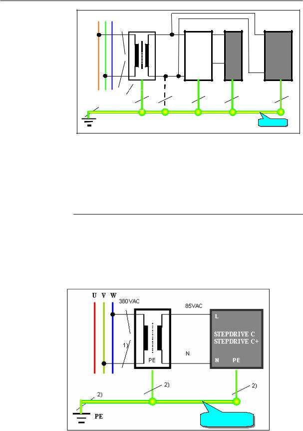
Drive transformer |
Use a separate drive transformer in the cabinet to supply the 85VAC power |
|
supply for stepper drives. Connections with the drive transformer are shown |
|
in Fig. 2-2. |
PE rails
Fig. 2-2 Connecting the drive transformer
2-2 |
SINUMERIK 801 |
|
Start-Up |
Start-Up
Notes (for Fig. 2-2):
1)Two phases of U V W that are not used by the control transformer;
2)In order to ensure a good grounding, the cross-sectional area of PE rails shall be not less than 6mm2.
Notice
When AC servo drives are used, please connect cables as per requirements concerned.
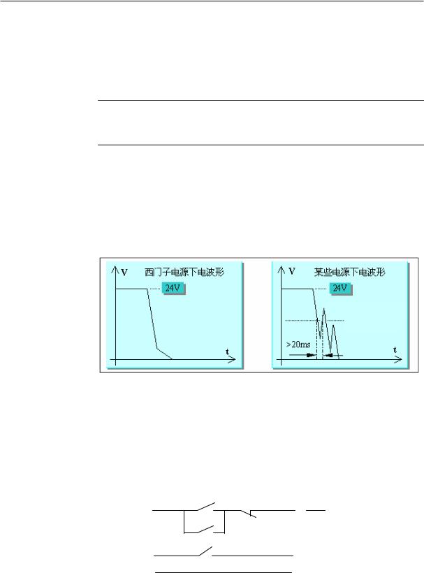
24VDC power supply
The SINUMERIK 801 CNC is supplied by a 24V DC power supply, which enables the control system to run in order under the voltage range of 24V-15% ... +20%. The excellent quality of the DC power supply is critical for the stable operation of the control system. You’re recommend to select Siemens 24VDC stabilized power supply (order number: 6EP1333-3BA00). If a DC power supply other than Siemens is used, please detect the output waveform generated when the power supply is switched off.
Waveform of Siemens PS |
|
Waveform of non-Siemens PS |
|
|
|
System operating volt: 24V min.
Fig. 2-3 The power supply waveform
If the waveform as shown in the upper right figure occurs, supply the SINUMERIK 801 in a way as indicated in the figure below and describe the system power-on sequences in the corresponding user guide for machine tools. Proper sequences are: switch on the mains for machine tools (to energize 24VDC power supply and drives) first, then supply the control system by pressing the button SA1; For switching off the control system, press SA2 first, then power off the mains for the machine tool.
|
SA1 |
SA2 |
KA1 |
|
|||
|
24VDC |
|
|
|
|
0VDC |
|
|
KA1 |
|
|
|
|
|
|
|
|
|
|
|
|
|
|
|
KA1 |
|
|
|
|
|
|
|
|
|
|
|
|
|
|
|
24VDC |
|
|
CNC |
|
|
|
|
0VDC |
|
|
|
|
||
|
|
|
|
|
|
|
|
|
|
|
|
|
|
|
|
|
|
|
|
|
|
|
|
|
Fig. 2-4 Power on/off sequence of the power supply |
||||||
|
Note: |
|
|
|
|
|
|
SINUMERIK 801 |
|
2-3 |
|||||
Start-Up |
|
|
|
|
|
|
|

Start-Up
1)All input signals must be level signals, i.e. level “0” (-3 ... 5VDC) and level “1” (11 ... 30VDC). Both suspended and high resistance signals are level “0”.
2-4 |
SINUMERIK 801 |
|
Start-Up |
Start-Up
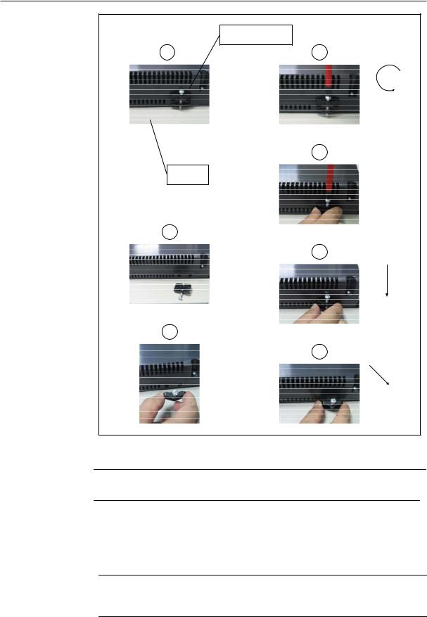
2.2Installing and cabling
2.2.1Installing the control system
!
General
Warning
Never install or dismantle when the control system is under power!
As an integrated control system, the SINUMERIK 801 CNC can be installed in the machine control station directly. Stepper drives or servo drives are installed in the cabinet. The SINUMERIK 801 can be fixed in the station from the rear side of the CNC with 8 black plastic clips (each of them is equipped with one M4x16 fastening screw) specific for the control system. The maximum allowable torque for each screw is 1.5 Nm.
Notice
Prior to the installation, the machine control panel can be provided with an emergency stop button. If it is not required, the opening must be covered with a self-adhesive cover delivered together with the SINUMERIK 801.
SINUMERIK 801 |
2-5 |
Start-Up |
|
Start-Up
Fig.2-5 Schematic diagram for the dismounting of SINUMERIK 801 CNC
Notice
The control system is mounted as described above in the reverse order!
Mounting dimensions
See figures below for the mounting dimensions of SINUMERIK 801 CNC, STEPDRIVE C/C+ and step motors.
Notice
When AC servo drives, servo motors are used, please refer to installation instructions concerned for mounting dimensions.
2-6 |
SINUMERIK 801 |
|
Start-Up |
Start-Up
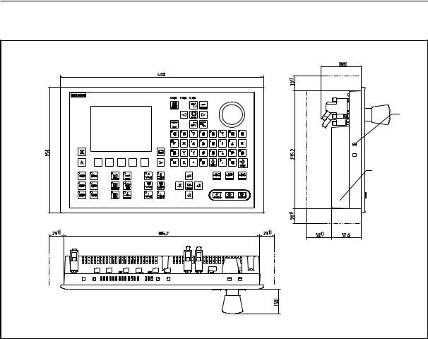
Mounting Dimensions
2)
SINUMERIK 801
1) Free space necessary for heat dissipation
2) Holes reserved for plastic clips with screws
Fig. 2-6 CNC outline dimensions
SINUMERIK 801 |
2-7 |
Start-Up |
|
Start-Up
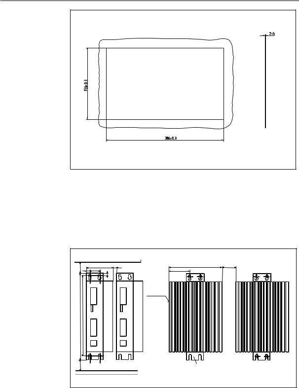
|
Fig. 2-7 Mounting hole dimensions |
Step drives |
To install the drive modules, proceed as follows (see vertical installation |
|
diagram shown in Fig. 2–8): |
1.Screw in the upper fastening screws M5 with spring washer and spacer.
2.Hang the module into the clips of the upper fastening bracket.
3.Screw in the lower fastening screws and tighten all screws.
|
Vertical installation (recommended) |
Horizontal installation |
|
||||||
|
(>150*) |
|
90 |
(100*) |
>100 |
|
176 |
(180*) |
>50 |
|
|
|
|
|
|
|
|
||
> 80 |
12 |
34 |
|
|
71 |
(73*) |
|
|
|
|
|
|
|
|
|
||||
|
|
|
7 |
|
|
|
|
||
|
|
|
|
|
|
PE rails |
|
|
|
|
(327*) |
(305.6*) |
|
|
|
|
|
|
|
|
307 |
286 |
|
|
|
|
|
|
|
|
> 80 |
(>100*) |
|
|
|
|
|
Changed installation angle |
|
|
|
|
|
|
|
|
|
||
|
Install with M5 screws, spacers and spring washers |
Without forced cooling |
|||||||
Fig. 2-8 Mounting dimensions for stepper drives
2-8 |
SINUMERIK 801 |
|
Start-Up |

Start-Up
Notice
Bracketed dimensions as shown in the figure above are suitable for STEPDRIVE C+.
The modules should be installed such that a clearance of at least 10 cm is left above, below and between the modules (dimension “a”).
The drive modules, however, can be mounted directly side by side (a>10 mm) provided they are ventilated with an air stream greater than / equal to 1 m/s.
Do not install devices which are strongly heated during operation beneath the drive modules!
Step motors
Fig. 2-9 Dimensions of the stepper motors (see Table 2-1)
Table 2-1 Outline dimensions of the stepper motors (see Fig. 2-9)
Model |
|
|
|
|
|
|
Dimensions and tolerance |
|
|
|
|
|
|
Key |
Wt. |
||||
D |
D1 |
D2 |
D3 |
D4 |
D5 |
|
L |
L1 |
L2 |
L3 |
L4 |
h |
h1 |
A |
B |
C |
(kg) |
||
|
|
|
|||||||||||||||||
6FC5 |
92 |
9f6 |
10 |
60f7 |
107 |
6.6 |
|
162 |
34 |
14 |
20 |
26 |
3 |
7 |
93 |
62.5 |
R10 |
C3X1 |
3 |
548-0AB03- |
|
||||||||||||||||||
|
4 |
||||||||||||||||||
0AA0 |
|
|
|
|
|
|
|
|
|
|
|
|
|
|
|
|
|
|
|
|
|
|
|
|
|
|
|
|
|
|
|
|
|
|
|
|
|
|
|
6FC5 |
|
|
|
|
|
|
|
|
|
|
|
|
|
|
|
|
10X4 |
C5X2 |
|
548-0AB06- |
110 |
16f6 |
17 |
56f7 |
127 |
8.5 |
|
186.5 |
34 |
25 |
32 |
37 |
2 |
12.5 |
112 |
65.0 |
5.6 |
||
|
5° |
5 |
|||||||||||||||||
0AA0 |
|
|
|
|
|
|
|
|
|
|
|
|
|
|
|
|
|
|
|
6FC5 |
110 |
16f6 |
17 |
56f7 |
127 |
8.5 |
|
216.5 |
34 |
25 |
32 |
37 |
2 |
12.5 |
112 |
65.0 |
10X4 |
C5X2 |
7.2 |
548-0AB09- |
|
||||||||||||||||||
|
5° |
5 |
|||||||||||||||||
0AA0 |
|
|
|
|
|
|
|
|
|
|
|
|
|
|
|
|
|
|
|
6FC5 |
|
|
|
|
|
|
|
|
|
|
|
|
|
|
|
|
10X4 |
C5X2 |
|
548-0AB12- |
110 |
16f6 |
17 |
56f7 |
127 |
8.5 |
|
248.5 |
34 |
25 |
32 |
37 |
2 |
12.5 |
112 |
65.0 |
8.6 |
||
|
5° |
5 |
|||||||||||||||||
0AA0 |
|
|
|
|
|
|
|
|
|
|
|
|
|
|
|
|
|
|
|
6FC5 |
130 |
16f6 |
17h |
100f7 |
155 |
10.5 |
|
239.0 |
34 |
32 |
36 |
43 |
3 |
15.0 |
132 |
90.0 |
10X4 |
C5X2 |
13.0 |
548-0AB18- |
|
||||||||||||||||||
7 |
|
5° |
5 |
||||||||||||||||
0AA0 |
|
|
|
|
|
|
|
|
|
|
|
|
|
|
|
|
|
|
|
6FC5 |
|
|
17h |
|
|
|
|
|
|
|
|
|
|
|
|
|
10X4 |
C5X2 |
|
548-0AB25- |
130 |
16f6 |
100f7 |
155 |
10.5 |
|
263.5 |
34 |
32 |
36 |
43 |
3 |
15.0 |
132 |
90.0 |
15.0 |
|||
7 |
|
5° |
5 |
||||||||||||||||
0AA0 |
|
|
|
|
|
|
|
|
|
|
|
|
|
|
|
|
|
|
|
When installing the stepper motor, its radial load shall stay within the data range listed below:
SINUMERIK 801 |
2-9 |
Start-Up |
|

Start-Up
|
|
|
|
|
|
|
|
|
|
|
|
|
|
|
|
|
Motor data |
|
|
|
|
Radial load |
|
|
|
|
Speed |
|
600 rev/min |
300 rev/min |
||
|
|
|
|
Shoulder distance |
|
20 mm |
20 mm |
|||
|
|
|
|
|
|
|
||||
|
|
|
|
|
|
Max. radial load |
|
950 N |
1150 N |
|
|
|
|
|
|
|
|
|
|
|
|
|
|
|
|
|
|
|
|
|
|
|
|
|
|
|
|
|
|
|
|
|
|
 20 mm
20 mm
Fig. 2-10 Radial load of the stepper motor
Frequency – torque characteristics of the stepper motors
2 8 ,0 0
2 6 ,0 0
2 4 ,0 0
2 2 ,0 0
2 0 ,0 0
1 8 ,0 0
1 6 ,0 0
1 4 ,0 0
1 2 ,0 0
1 0 ,0 0
8 ,0 0
6 ,0 0
4 ,0 0
2 ,0 0
0 ,0 0
0 ,1 0 |
1 ,0 0 |
F r e q u e n c y [K H z ] |
1 0 ,0 0 |
|
|
|
|
||
6 |
6 0 |
S P E E D |
[R P M ] |
6 0 0 |
|
|
|
||
Fig. 2-11 Frequency – torque characteristics of the stepper motors
2-10
 6 F C 5 5 4 8 -0 A B 2 5 -0 A A 0
  6 F C 5 5 4 8 -0 A B 1 8 -0 A A 0
 6 F C 5 5 4 8 -0 A B 1 2 -0 A A 0
 6 F C 5 5 4 8 -0 A B 0 9 -0 A A 0
 6 F C 5 5 4 8 -0 A B 0 6 -0 A A 0
  6 F C 5 5 4 8 -0 A B 0 3 -0 A A 0
1 0 0 ,0 0
6 0 0 0
SINUMERIK 801
Start-Up

Start-Up
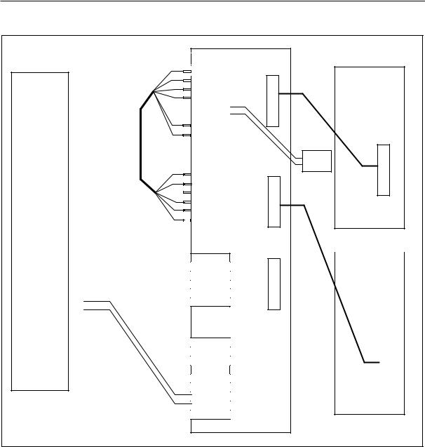
2.2.2Cabling
2.2.2.1Connecting with the stepper drives
Cable overview Connect the STEPDRIVE C/C+ drive modules, the stepper motors and the SINUMERIK 801 control system as shown in the connection diagram 2-12. For the cables required, please refer to the diagram below.
X1

X2
X4
|
|
|
|
|
|
|
|
|
|
|
|
|
|
|
|
|
|
|
|
|
|
|
|
|
|
|
|
|
|
|
|
|
|
|
|
|
|
|
|
|
|
|
|
|
|
|
|
|
|
|
|
|
|
|
|
|
|
|
|
|
|
|
|
|
|
|
|
|
|
|
|
|
|
|
|
|
|
|
|
|
|
|
|
|
|
|
|
|
|
|
|
|
|
|
|
|
X3 |
|
|
|
|
|
|
|
|
|
|
|
|
|
|
|
|
|
|
|
|
|
|
|
|
|
|
|
|
|
|
|
|
|
|
|
|
|
|
|
|
|
|
|
|
|
|
|
|
|
|
|
|
|
|
|
|
|
|
|
|
|
|
|
|
|
|
|
|
|
|
|
|
|
|
|
|
|
|
|
|
|
|
|
|
|
|
|
|
|
|
|
|
|
|
|
|
X10 |
|
|
|
|
|
|
|
|
|
|
|
|
|
|
|
|
|
|
|
|
|
|
|
|
|
|
|
|
|
|
|
|
|
|
|
|
|
|
|
|
|
|
|
|
|
|
|
|
|
|
|
|
|
|
|
|
|
|
|
|
|
|
|
|
|
|
|
|
|
|
|
|
|
|
|
|
|
|
|
|
|
|
|
|
|
|
|
|
|
|
|
|
|
|
|
|
|
|
|
|
|
|
|
|
|
|
|
|
|
|
|
|
|
|
|
|
|
|
X20 |
|
|
|
|
|
|
|
|
|
|
|
|
|
|
|
|
|
|
|
|
|
|
|
|
|
|
|
|
|
|
|
|
|
|
|
|
|
|
|
|
|
|
|
|
||
|
|
|
|
|
|
|
|
|
|
|
|
|
|
|
|
|
|
|
|
|
|
||
|
|
|
|
|
|
|
|
|
|
|
|
|
|
|
|
|
|
|
|
|
|
|
|
|
|
|
|
|
|
|
|
|
|
|
|
|
|
|
|
|
|
|
|
|
|
|
|
|
|
|
|
|
|
|
|
|
|
|
|
|
|
|
|
|
|
|
|
|
|
|
|
|
|
|
|
|
|
|
|
|
|
|
|
|
|
|
|
|
|
|
|
|
|
|
|
|
X100 |
X101 |
|
|
|
|
|
|
|
|
|
|
|
|
|
|
|
|
|
|
|
|
|
|
|
|
|
|
|
|
|
|
|
|
|
|
|
|
|
|
|
|
|
|
|||
|
|
|
|
|
|
|
|
|
|
|
|
|
|
|
|
|
|
|
|
||||
|
|
|
|
|
|
|
|
|
|
|
|
|
|
|
|
|
|
|
|
|
|
|
|
|
|
|
|
|
|
|
|
|
|
|
|
|
|
|
|
|
|
|
|
|
|
|
|
|
|
|
|
|
|
|
|
|
|
|
|
|
|
|
|
|
|
|
|
|
|
|
|
|
X200 |
X201 |
|
|
|
|
|
|
|
|
|
|
|
|
|
|
|
|
|
|
|
|
|
|
|
|
|
|
|
|
|
|
|
|
|
|
|
|
|
|
|
|
|
|
|||
|
|
|
|
|
|
|
|
|
|
|
|
|
|
|
|
|
|
|
|
||||
|
|
|
|
|
|
|
|
|
|
|
|
|
|
|
|
|
|
|
|
|
|||
|
|
|
|
|
|
|
|
|
|
|
|
|
|
|
|
|
|
|
|
|
|
|
|
|
|
|
|
|
|
|
|
|
|
|
|
|
|
|
|
|
|
|
|
|
|
|
|
|
|
|
|
|
|
|
|
|
|
|
|
|
|
|
|
|
|
|
|
|
|
|
|
Fig. 2-12 Overview of cables
SINUMERIK 801 |
2-11 |
Start-Up |
|

Start-Up
2.2.2.2Connecting with the servo drives (example)
Notice
Adaptor, servo motor, servo drive and cable for connecting the adaptor to the servo drive are not included in the scope of supply of the SINUMERIK 801 control system.
Axis/Spindle |
|
X4 |
|
|
|
SINUMERIK |
|
||
801 CNC |
|
||
BERO |
|
X20 |
3 |
|
|||
|
4 |
||
|
|
||
|
|
10 |
|
|
|
|
|
Signal cable:
6FX6002-5AA52-1..0
|
|
|
CN1 |
|
|
P1 |
|
|
|
||
|
X-PLUS1 |
||||
P1N |
|
X-PLUS2 |
|
||
D1 |
|
X-SIGN1 |
|
||
D1N |
|
|
|
|
|
|
X-SIGN2 |
|
|||
|
|
|
|||
|
|
24V_GND |
|
||
|
|
|
|
|
|
E1 |
24V |
|
|
E1 |
|
||
|
|
||
E1N |
E1N |
|
|
|
GS |
|
|
|
CN2 |
|
|
P2 |
Y-PLUS1 |
|
|
|
|
||
P2N |
Y-PLUS2 |
|
|
D2 |
Y-SIGN1 |
|
|
D2N |
|
||
Y-SIGN2 |
ADAPTOR |
||
E2 |
|||
E1 |
|||
|
|||
|
|
||
E2N |
E1N |
|
|
|
|
||
|
GS |
|
|
|
CN3 |
PANASONIC |
|
|
|
W |
|
|
i |
|
|
r |
|
|
e |
|
|
( |
|
|
W |
f |
|
o |
|
|
i |
r |
CN4 |
e |
||
r |
B |
|
e |
|
|
( |
r |
|
f |
o |
|
o |
|
|
r |
1 |
|
B |
) |
|
e |
|
|
r |
|
|
o |
|
|
2 |
|
|
|
) |
|
M24 |
|
|
HMX |
HMY |
X-AXIS
Y-AXIS
Z-AXIS
PANASONIC
AC SERVO DRIVE
C o n n e c t i o n
c a b l e
24Vdc - power +
X5
C |
|
|
|
o |
|
|
|
n |
PANASONIC |
||
t |
|||
n |
|
|
|
e |
|
|
|
c |
AC SERVO DRIVE |
||
c |
|||
io |
|
|
|
n |
|
|
|
a |
|
|
|
b |
|
|
|
l |
|
|
|
e |
|
|
|
|
|
|
|
|
|
|
|
X5
Fig. 2-13 Connecting with the servo drives (SINUMERIK 801+ Panasonic Adaptor + Panasonic Servo Drives)
2-12 |
SINUMERIK 801 |
|
Start-Up |
Start-Up
Axis/Spindle |
|
X4 |
Signal cable: |
|
|
|
|
|
|
|
|
|
|
|
|
|
|
|
6FX6002-5AA52-1..0 |
|
|
|
|
SINUMERIK |
|
|
|
|
|
|
||
801 CNC |
|
|
|
|
|
|
||
|
|
|
|
|
|
|
|
|
BERO |
X20 |
3 |
|
|
|
|
|
|
4 |
|
|
|
W |
|
|||
|
|
|
|
|
|
|
i |
|
|
|
|
|
|
|
|
r |
|
|
|
|
|
|
|
|
e |
|
|
|
|
|
( |
||||
|
|
|
|
|
|
W |
f |
|
|
|
|
|
|
|
o |
||
|
|
|
|
|
|
i |
r |
|
|
|
|
|
|
|
r |
B |
|
|
|
|
|
|
|
e |
e |
|
|
|
|
|
|
|
( |
||
|
|
|
|
|
|
r |
||
|
|
|
|
|
|
|
f |
o |
|
|
10 |
|
|
|
o |
||
|
|
|
|
|
B |
) |
||
|
|
|
|
|
|
|
r |
1 |
|
|
|
|
|
|
|
|
|
|
|
|
|
|
|
|
e |
|
|
|
|
|
|
|
|
r |
|
|
|
|
|
|
|
|
o |
|
|
|
|
|
|
|
2 |
||
|
|
|
|
|
|
|
|
) |
|
|
|
|
|
M24 |
|
|
|
|
|
|
|
|
|
|
|
|
|
|
J1 |
|
|
|
||
P1 |
|
X_PLUS1 |
|
P1N |
X_PLUS2 |
||
D1 |
|
|
|
|
X_SIGN1 |
||
D1N |
|
X_SIGN2 |
|
|
|
||
|
|
+24V_GND |
|
E1 |
|
+24V |
|
|
X_E1 |
||
|
|
||
E1N |
|
X_E1N |
|
|
|
|
|
J2 |
|
P2 |
|
|
|
||
|
Y_PLUS1 |
||||
|
|
|
|
||
P2N |
|
Y_PLUS2 |
|||
|
|||||
D2 |
|
|
Y_SIGN1 |
||
|
|||||
D2N |
|
||||
|
Y_SIGN2 |
||||
|
|||||
E2 |
|
||||
|
Y_E1 |
||||
|
|||||
|
|
|
|
||
E2N |
|
Y_E1N |
|||
|
|||||
|
|
|
|
||
|
|
|
|||
J3 |
J4
HMX |
HMY |
GOLDEN AGE ADAPTOR
J5
J6
J7
GOLDEN AGE
AC SERVO DRIVE
C o n n e c t i o n
c a b l e
24Vdc - power +
XS3
C |
|
|
|
o |
|
|
|
n |
GOLDEN AGE |
||
t |
|||
n |
|
|
|
e |
|
|
|
c |
AC SERVO DRIVE |
||
c |
|||
io |
|
|
|
n |
|
|
|
a |
|
|
|
b |
|
|
|
l |
|
|
|
e |
|
|
|
|
|
|
|
|
|
|
|
XS3
Fig. 2-14 Connecting with the servo drives (SINUMERIK 801+ Golden Age Adaptor + Golden Age Servo Drives)
SINUMERIK 801 |
2-13 |
Start-Up |
|
Start-Up
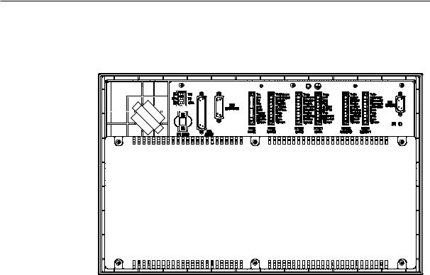
2.3Interfaces and Cables
Position of the |
See Fig. 2-15 for interface positions. |
||||||||||||||||||
interfaces |
|
|
|
|
|
|
|
|
|
|
|
|
|
|
|
|
|
|
|
|
|
|
|
|
|
|
|
|
|
|
|
|
|
|
|
|
|
|
|
|
|
|
|
|
|
|
|
|
|
|
|
|
|
|
|
|
|
|
|
|
|
|
|
|
|
|
|
|
|
|
|
|
|
|
|
|
|
|
|
|
|
|
|
|
|
|
|
|
|
|
|
|
|
|
|
|
|
|
|
|
|
|
|
|
|
|
|
|
|
|
|
|
|
|
|
|
|
|
|
|
|
|
|
|
|
|
|
|
|
|
|
|
|
|
|
|
|
|
|
|
|
|
|
|
|
|
|
|
|
|
|
|
|
|
|
|
|
|
|
Fig. 2-15 Rear of CNC System
2-14 |
SINUMERIK 801 |
|
Start-Up |
 Loading...