


808D
Table of contents
 Loading...
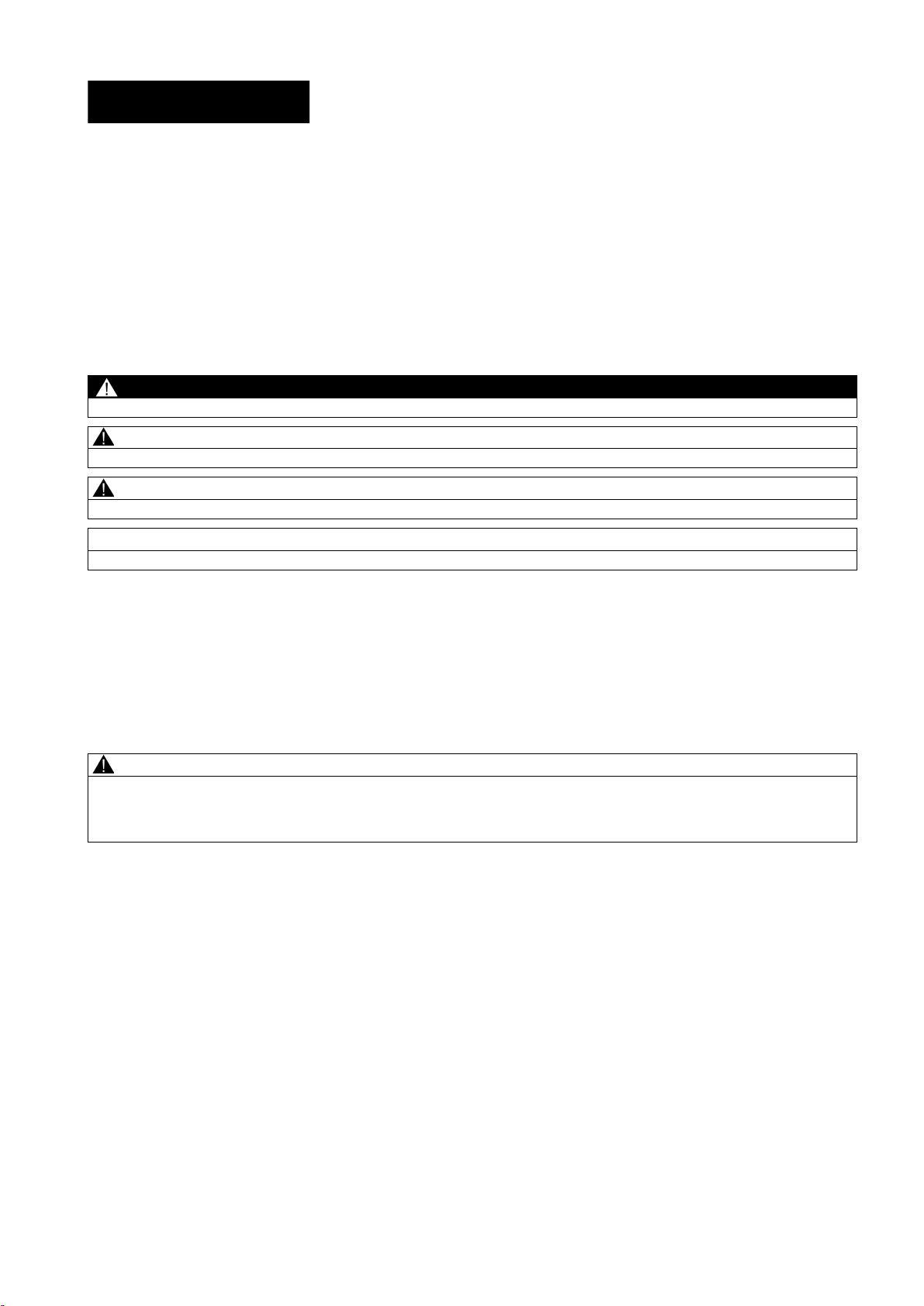
SINUMERIK
SINUMERIK 808D ADVANCED
PLC Subroutines Manual
User Manual
Legal information
Warning notice system
DANGER
will
WARNING
may
CAUTION
NOTICE
Qualified Personnel
personnel qualified
Proper use of Siemens products
WARNING
This manual contains notices you have to observe in order to ensure your personal safety, as well as to prevent damage to property. The
notices referring to your personal safety are highlighted in the manual by a safety alert symbol, notices referring only to property damage
have no safety alert symbol. These notices shown below are graded according to the degree of danger.
indicates that death or severe personal injury
indicates that death or severe personal injury
indicates that minor personal injury can result if proper precautions are not taken.
indicates that property damage can result if proper precautions are not taken.
If more than one degree of danger is present, the warning notice representing the highest degree of danger will be used. A notice warning of
injury to persons with a safety alert symbol may also include a warning relating to property damage.
result if proper precautions are not taken.
result if proper precautions are not taken.
The product/system described in this documentation may be operated only by
the relevant documentation, in particular its warning notices and safety instructions. Qualified personnel are those who, based on their
training and experience, are capable of identifying risks and avoiding potential hazards when working with these products/systems.
for the specific task in accordance with
Note the following:
Siemens products may only be used for the applications described in the catalog and in the relevant technical documentation. If products
and components from other manufacturers are used, these must be recommended or approved by Siemens. Proper transport, storage,
installation, assembly, commissioning, operation and maintenance are required to ensure that the products operate safely and without any
problems. The permissible ambient conditions must be complied with. The information in the relevant documentation must be observed.
© Siemens AG 2012 - 2013. All rights reserved
6FC5397-0FP40-0BA0, 08/2013
1

Preface
Applicable products
Control system
Software version
Documentation components and target groups
Component
Recommended target group
User documentation
Manufacturer/service documentation
My Documentation Manager (MDM)
Standard scope
Technical support
Hotline:
Service and Support:
EC Declaration of Conformity
15257461
This manual is applicable to the following control systems:
SINUMERIK 808D ADVANCED T (Turning) V4.6
SINUMERIK 808D ADVANCED M (Milling) V4.6
Programming and Operating Manual (Turning) Programmers and operators of turning machines
Programming and Operating Manual (Milling) Programmers and operators of milling machines
Programming and Operating Manual (ISO Turning/Milling) Programmers and operators of turning/milling machines
Programming and Operating Manual (Manual Machine Plus
Turning)
Diagnostics Manual Mechanical and electrical designers, commissioning
Commissioning Manual Installation personnel, commissioning engineers, and
Function Manual Mechanical and electrical designers, technical professionals
Parameter Manual Mechanical and electrical designers, technical professionals
PLC Subroutines Manual Mechanical and electrical designers, technical
Programmers and operators of turning machines
engineers, machine operators, and service and
maintenance personnel
service and maintenance personnel
professionals, and commissioning engineers
Under the following link you will find information to individually compile your documentation based on the Siemens content:
www.siemens.com/mdm
This manual only describes the functionality of the standard version. Extensions or changes made by the machine tool
manufacturer are documented by the machine tool manufacturer.
● Global support hotline:
+49 (0)911 895 7222
● Support hotline in China:
+86 4008104288 (china)
The EC Declaration of Conformity for the EMC Directive can be found on the Internet at
http://support.automation.siemens.com
Here, enter the number
PLC Subroutines Manual
2 6FC5397-0FP40-0BA0, 08/2013
● Chinese Web site:
http://www.siemens.com.cn/808D
● Global Web site:
http://support.automation.siemens.com
as the search term or contact your local Siemens office.

Table of contents
Preface ................................................................................................................................................................... 2
1 Overview ................................................................................................................................................................ 4
2 PLC Programming Tool ........................................................................................................................................... 7
3 PLC subroutines ................................................................................................................................................... 32
2.1 Installing the 808D Toolbox ........................................................................................................................... 7
2.2 PLC instructions ............................................................................................................................................ 8
2.3 Data management......................................................................................................................................... 9
2.4 Program organization .................................................................................................................................... 9
2.5 Testing and monitoring your program ......................................................................................................... 10
2.6 Establishing a connection with the RS232 interface ................................................................................... 13
2.7 Establishing a direct connection with the Ethernet interface ....................................................................... 17
2.8 Establishing a network connection with the Ethernet interface ................................................................... 20
2.9 PLC application Download/Upload/Copy/Compare ..................................................................................... 22
3.1 PLC machine data....................................................................................................................................... 32
3.2 Conventions for the symbols used in the subroutines ................................................................................. 32
3.3 Subroutine 20 - AUX_MCP (machine auxiliary functions) ........................................................................... 34
3.4 Subroutine 21 - AUX_LAMP (working lamp) ............................................................................................... 35
3.5 Subroutine 22 - AUX_SAFE_DOOR (safe door) ......................................................................................... 35
3.6 Subroutine 23 - AUX_CHIP (chip remover) ................................................................................................. 36
3.7 Subroutine 31 - PLC_ini_USR_ini (user initialization) .................................................................................. 36
3.8 Subroutine 32 - PLC_INI (PLC initialization) ............................................................................................... 36
3.9 Subroutine 33 - EMG_STOP ....................................................................................................................... 37
3.10 Subroutine 37 - MCP_NCK (MCP and HMI signal processing) ................................................................... 38
3.11 Subroutine 38 - MCP_Tool_Nr (display tool number on the MCP) .............................................................. 39
3.12 Subroutine 39 - HANDWHL (selecting a handwheel according to HMI interface signals) ........................... 39
3.13 Subroutine 40 - AXIS_CTL (controlling the spindle and axes) .................................................................... 40
3.14 Subroutine 41 - MINI_HHU (handwheel hand-held unit) ............................................................................. 42
3.15 Subroutine 42 - SPINDLE (spindle control) ................................................................................................. 43
3.16 Subroutine 43 - MEAS_JOG (measurement in the JOG mode) .................................................................. 44
3.17 Subroutine 44 - COOLING (cooling control) ................................................................................................ 45
3.18 Subroutine 45 - LUBRICAT (control of lubricate) ........................................................................................ 46
3.19 Subroutine 46 - PI_SERVICE (Asynchronous Subroutine Program) ........................................................... 47
3.20 Subroutine 47 - PLC_Select_PP (PLC selects a subroutine) ...................................................................... 48
3.21 Subroutine 48 - ServPlan (service plan) ...................................................................................................... 49
3.22 Subroutine 49 - GearChg1_Auto (automatic spindle gear change) ............................................................. 50
3.23 Subroutine 50 - GearChg2_Virtual (virtual spindle gear change) ................................................................ 51
3.24 Subroutine 51 - Turret1_HED_T (turret with Hall effect device position sensor) ......................................... 52
3.25 Subroutine 52 - TURRET2_BIN_T (turret with binary coding function)........................................................ 54
3.26 Subroutine 53 - Turret3_CODE_T (tool change control for turret with coding function) .............................. 56
PLC Subroutines Manual
6FC5397-0FP40-0BA0, 08/2013
3

4 Use of user alarms in the PLC subroutines .............................................................................................................67
5 PLC sample applications .......................................................................................................................................68
Index ....................................................................................................................................................................74
1
Overview
WARNING
System resource distribution
3.27 Subroutine 54 - Turret2_3_ToolDir (tool change direction) ......................................................................... 57
3.28 Subroutine 55 - Tail_stock_T (Tailstcok control program for turning machines) ......................................... 59
3.29 Subroutine 56 - Lock_unlock_T (clamping control for turning machines) .................................................... 59
3.30 Subroutine 58 (MM_MAIN) ......................................................................................................................... 61
3.31 Subroutine 59 (MM_MCP_808D) ................................................................................................................ 63
3.32 Subroutine 60 - Disk_MGZ_M (disk-style tool magazine for milling) ........................................................... 64
3.33 Subroutines 34 to 36, 57, 61 and 62 ........................................................................................................... 66
3.34 Subroutine 63 - TOGGLES ......................................................................................................................... 66
5.1 PLC sample application (turning) ................................................................................................................ 68
5.2 PLC sample application (milling) ................................................................................................................ 71
The PLC subroutines consist of three project files:
● default_turning.ptp (sample application for turning machines)
● default_milling.ptp (sample application for milling machines)
● default_ManMachPlus_T.ptp (sample application for Manual Machine Plus)
With the sample applications, you can get a good understanding about how to create or call a PLC subroutine. You can
realize most machine functions by re-organizing the PLC subroutines or modifying some must networks.
Make sure that you perform a complete machine test to all subroutines used in your main program, in order to verify that all
the subroutines called by the main program function as you desire. Failure to observe may cause personal injury or
property damage.
The system resources can be distributed into three parts:
● PLC system
– Inputs
I0.0 to I2.7 (24 inputs of the SINUMERIK 808D ADVANCED)
I3.0 to I8.7 (distributed 48 inputs)
– Outputs
Q0.0 to Q1.7 (16 outputs of the SINUMERIK 808D ADVANCED)
Q2.0 to Q5.7 (distributed 32 outputs)
– Memory
M0.0 to M255.7 (256 bytes)
– Non-volatile memory
DB1400.DBX0.0 to DB1400.DBX127.7 (128 bytes)
– PLC user alarms:
DB1600.DBX0.0 to DB1600.DBX15.7 (128 user alarms)
– Timer
T0 to T15 (100ms timer)
PLC Subroutines Manual
4 6FC5397-0FP40-0BA0, 08/2013

Structure of the symbol tables
Symbol table
Table name
Descriptions
Structure of the subroutines
Subroutine No.
Name
Description
T16 to T63 (10ms timer)
– Counter
C0 to C63 (64 counters)
● NCK
– PLC machine data: MD14510, MD14512, MD 14514
– MD14510 machine data INT: DB4500.DBW0 to DB4500.DBW62 (32 words)
– MD14512 machine data hex: DB4500.DBB1000 to EDB4500.DBB1031 (32 bytes)
– MD14514 machine data real: DB4500.DBD2000 to DB4500.DBD2028 (8 Dword)
● PLC Programming Tool
– Symbol table: SYM1 to SYM32 (32 symbol tables)
– Subroutine: SBR0 to SBR63 (64 subroutines)
The PLC subroutine library has been designed with symbol addressing method, which helps you easily understand the PLC
programs. All the addresses in the subroutine library use symbols for programming. All the interface signals are named with
symbols and assigned to different symbol tables.
1 IO_1 Module I/O are defined by the manufacturer
2 IO_2 Distributed I/O are defined by the manufacturer
3, 5, 7, 13 Reserved for the manufacturer
6 MANMACH JOG function
14 ASUP ASUP function
15 PLC_sel_PP PLC selects part programs
16 IS_MCP Signals from/to the MCP
17 IS_HMI Signals from/to the HMI
18 IS_AUX Auxiliary functions from the NCK
19 IS_NCK Signals from/to the NCK
20 IS_CHA Signals from/to the channel
21 IS_AX1 Signals to/from axis 1
22 IS_AX2 Signals to/from axis 2
23 IS_AX3 Signals to/from axis 3
24 IS_AX4 Signals to/from axis 4
27 MD_PLC PLC machine data
28 ALARM User alarms
29 NV_MEM Non-volatile memory
30 SPC_MEM Special memory bit
31 SBR_MEM Global memory used in the sample applications and subroutines
32 RESVD1 Reserved for the sample applications and subroutines
PLC Subroutines Manual
6FC5397-0FP40-0BA0, 08/2013
0 to 19 - Reserved for the manufacturer
20 AUX_MCP Auxiliary function
21 AUX_LAMP Lamp control, called in the subroutine "AUX_MCP".
22 AUX_SAFE_DOOR Safe door control, called in the subroutine "AUX_MCP" of a milling
application.
5

Subroutine No.
Name
Description
Chip remover control, called in the subroutine "AUX_MCP" of a milling
MCP interface description
Input/output
DB number
Bit7
Bit6
Bit5
Bit4
Bit3
Bit2
Bit1
Bit0
23 AUX_CHIP
application.
31 PLC_ini_USR_INI Reserved for the initialization by the manufacturer (this subroutine is
automatically called by subroutine 32)
32 PLC_INI PLC initialization
33 EMG_STOP Emergency Stop
37 MCP_NCK Signals from the MCP and the HMI are sent to NCK interfaces
38 MCP_Tool_Nr Display tool numbers via the LED of the MCP
39 HANDWHL Handwheel selection via HMI
40 AXIS_CTL Control of feed axis enable and spindle enable
41 MINI_HHU Handwheel hand held unit
42 SPINDLE Spindle function
43 MEAS_JOG Tool measurement in the JOG mode
44 COOLING Coolant control (Manual Machine key and M code: M07, M08, M09)
45 LUBRICATE Lubrication control (interval and time)
46 PI_SERVICE ASUP (Asynchronous Subroutine Program)
47 PLC_Select_PP PLC selects a subroutine.
48 ServPlan Service plan
49 Gear_Chg1_Auto Automatic gear change of the spindle
50 Gear_Chg2_Virtual Dummy gear change of the spindle
51 Turret1_HED_T Turret control of the turning machine (turret type: Hall element
transistor, 4/6 position)
52 Turret2_BIN_T Turret control of the turning machine (turret type: position detection
with encodings)
53 Turret3_CODE_T Hydraulic turret control of the turning machine (turret type: position
detection with encodings)
54 Turret2_3_ToolDir Evaluate tool direction and calculate tool position (called by
Turret2_BIN_T, Turret3_CODE_T)
55 Tail_stock_T Tail stock control for the turning machine
56 Lock_unlock_T Clamp or release control for the turning machine
58 MM_MAIN Manual machine
59 MM_MCP_808D Spindle signal processing for the manual machine
60 Disk_MGZ_M Disk tool magazine for a milling machine
61, 62 Reserved for the subroutine
63 TOGGLE Six key-operated switches: K1 to K6
Two delay switches: K7, K8
Input (MCP ->
PPU),
DB1000
PLC Subroutines Manual
DB1000.DBB0 M01 Program
test
DB1000.DBB1 Key 16 Key 15 Key 14 Key 13 Key 12 Key 11 Key 10 ROV
DB1000.DBB2 100
(INC)
DB1000.DBB3 Key 32 Key 31 Cycle
DB1000.DBB4 Key 39 Key 38 Key 37 Key 36 RAPID Key 34 Key 33
DB1000.DBB5
10 (INC) 1 (INC) Key 21 Key 20 Key 19 Key 18 Key 17
MDA Single
start
6 6FC5397-0FP40-0BA0, 08/2013
block
Cycle
Stop
AUTO REF.
POINT
RESET Spindle
right
JOG Hand-
wheel
Spindle
Stop
Spindle
left

Input/output
DB number
Bit7
Bit6
Bit5
Bit4
Bit3
Bit2
Bit1
Bit0
Note
2
PLC Programming Tool
2.1
Installing the 808D Toolbox
DB1000.DBB6
DB1000.DBB7
DB1000.DBB8 Feed override value (in Gray code)
DB1000.DBB9 Spindle override value (in Gray code)
DB1000.DBB10
Output (PPU > MCP),
DB1100
1)
The decimal point of the 7 SEG LED 1.
2)
The decimal point of the 7 SEG LED 2.
DB1100.DBB0 LED 8 LED 7 LED 6 LED 5 LED 4 LED 3 LED 2 LED 1
DB1100.DBB1 LED
16
DB1100.DBB2 LED
24
DB1100.DBB3 LED 30 LED 29 LED 28 LED 27 LED 26 LED 25
DB1100.DBB4
DB1100.DBB5
DB1100.DBB6
DB1100.DBB7
DB1100.DBB8 7 SEG LED 1
DB1100.DBB9 7SEG LED 2
DB1100.DBB10
DB1100.DBB11
DB1100.DBB12 DP 2 2) DP 1 1)
LED 15 LED 14 LED 13 LED 12 LED 11 LED 10 LED 9
LED 23 LED 22 LED 21 LED 20 LED 19 LED 18 LED 17
Interfaces where nothing has been entered are reserved for the next version.
You can understand the relationship between the PLC interface addresses and the SINUMERIK 808D MCP from the
following illustration for a horizontal MCP:
You must install the 808D Toolbox on your PC/PG (PLC Programming Tool). The 808D Toolbox contains the following
software tools and information:
● Config Data 808D
– System software update
– Examples (EasyXLanguage, symbols for MCP customized keys, template for MCP strips, PLC subroutine library)
PLC Subroutines Manual
6FC5397-0FP40-0BA0, 08/2013
7

Installing the 808D toolbox
Setup.exe
2.2
PLC instructions
● PLC Programming Tool
The tool for creating PLC user programs
● Windows setup software for toolbox
● User documentation
● License information and conditions about Open Source Software (Readme_OSS)
● SinuComPCIN
● Access MyMachine P2P (AMM)
The toolbox installation folder is shown below:
To start the installation, double-click the
install.
Various instructions are available in the PLC Programming Tool. You can view them in the instruction branch on the
instruction tree:
file. In the setup dialog, select one or multiple options that you desire to
PLC Subroutines Manual
8 6FC5397-0FP40-0BA0, 08/2013
2.3
Data management
2.4
Program organization
You can right-click over an instruction or directly press the F1 key to view its help information. For example:
The data can be broken down into three areas:
● non-retentive data
● retentive data
● machine data for the PLC (this machine data is all active at POWER ON)
Most data, such as the process image, timers, and counters are non-retentive and are cleared each time the control system
is restarted.
For the retentive data, there is a data range of 1400 0000 -1400 0127. This location can be used to save all the data which is
to remain valid after POWER OFF/ON.
With the aid of the PLC-MD (see user interface), you can pre-assign your program with data or parameterize various parts of
the program.
When programming the PLC, you must structure your program into finished program parts (subroutines). The programming
language for S7-200 offers you the capability to set up your user program in a structured manner.
There are the following two types of programs:
● The main program
● The subroutine.
Eight levels of programming are possible.
PLC Subroutines Manual
6FC5397-0FP40-0BA0, 08/2013
9

2.5
Testing and monitoring your program
Testing and monitoring a PLC program with the HMI
→
You can check or perform an error analysis of the user program in two methods:
● HMI of the SINUMERIK 808D ADVANCED
● PLC Programming Tool
There are three ways for program testing and monitoring in the <SYSTEM> operating area ( + ):
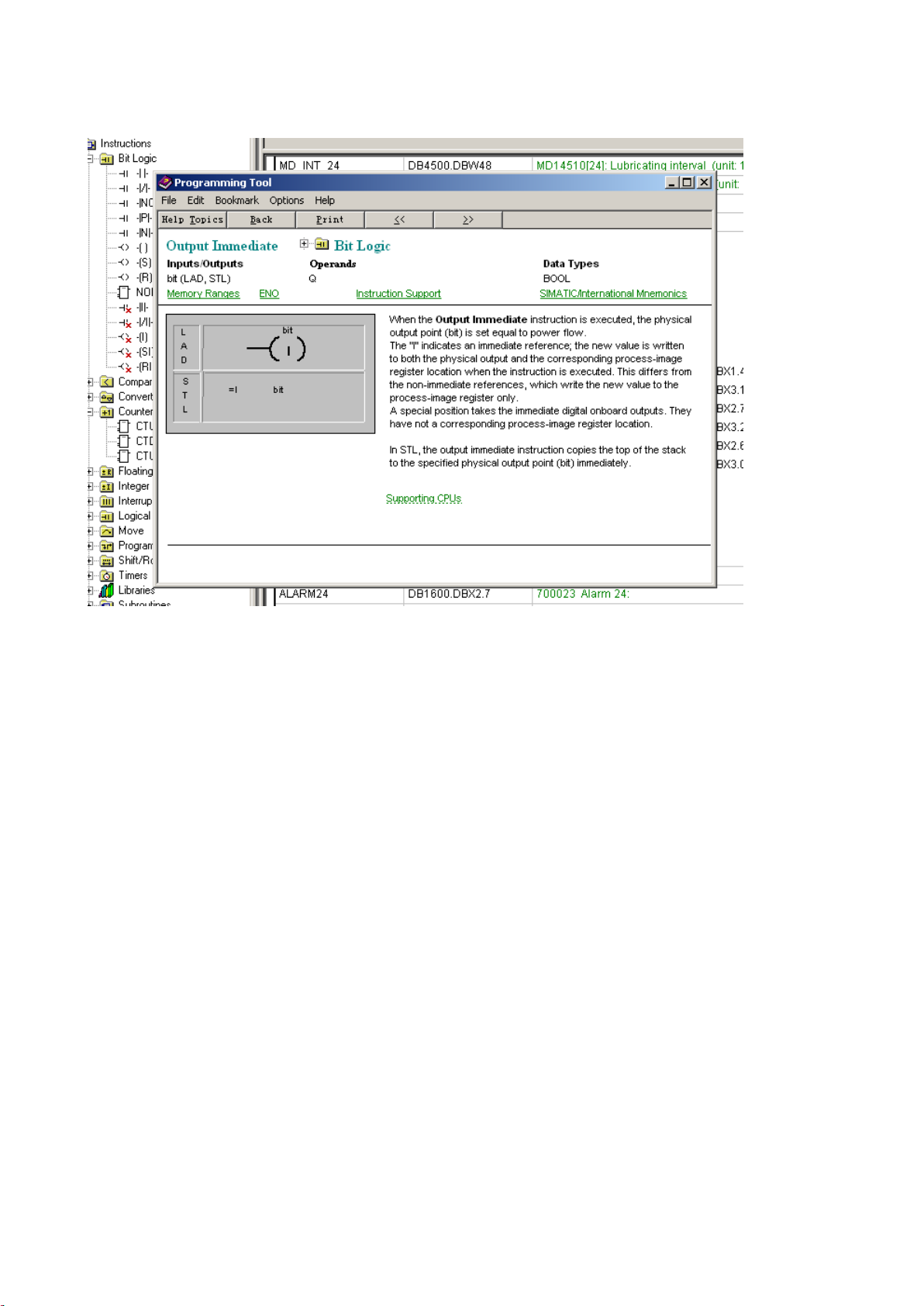
●
You can enter an operand to view its status.
Use the softkey
softkey to change the value of the operand and the
or respectively to increase/decrease the bit of the operand. Use the
softkey to delete all the entered operands.
● →
PLC Subroutines Manual
10 6FC5397-0FP40-0BA0, 08/2013
You can view the status of a PLC signal.
By default, three signal status lists (inputs, flags and outputs) are displayed in three columns. You can change column
sequence or assign a new signal status list (variables) with the
softkey.
You can also change the status of a PLC signal with the softkey.
PLC Subroutines Manual
6FC5397-0FP40-0BA0, 08/2013
11
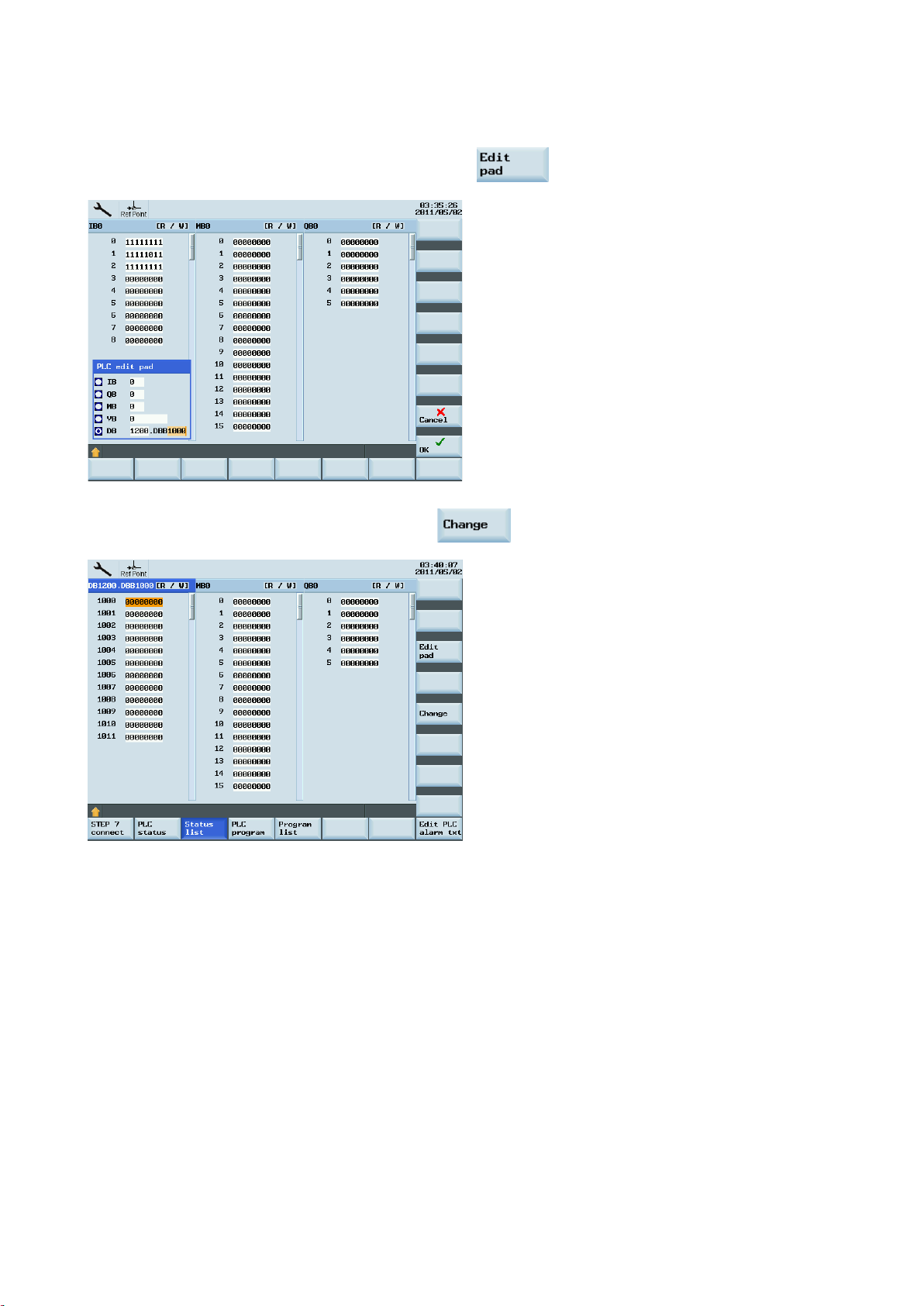
→
●
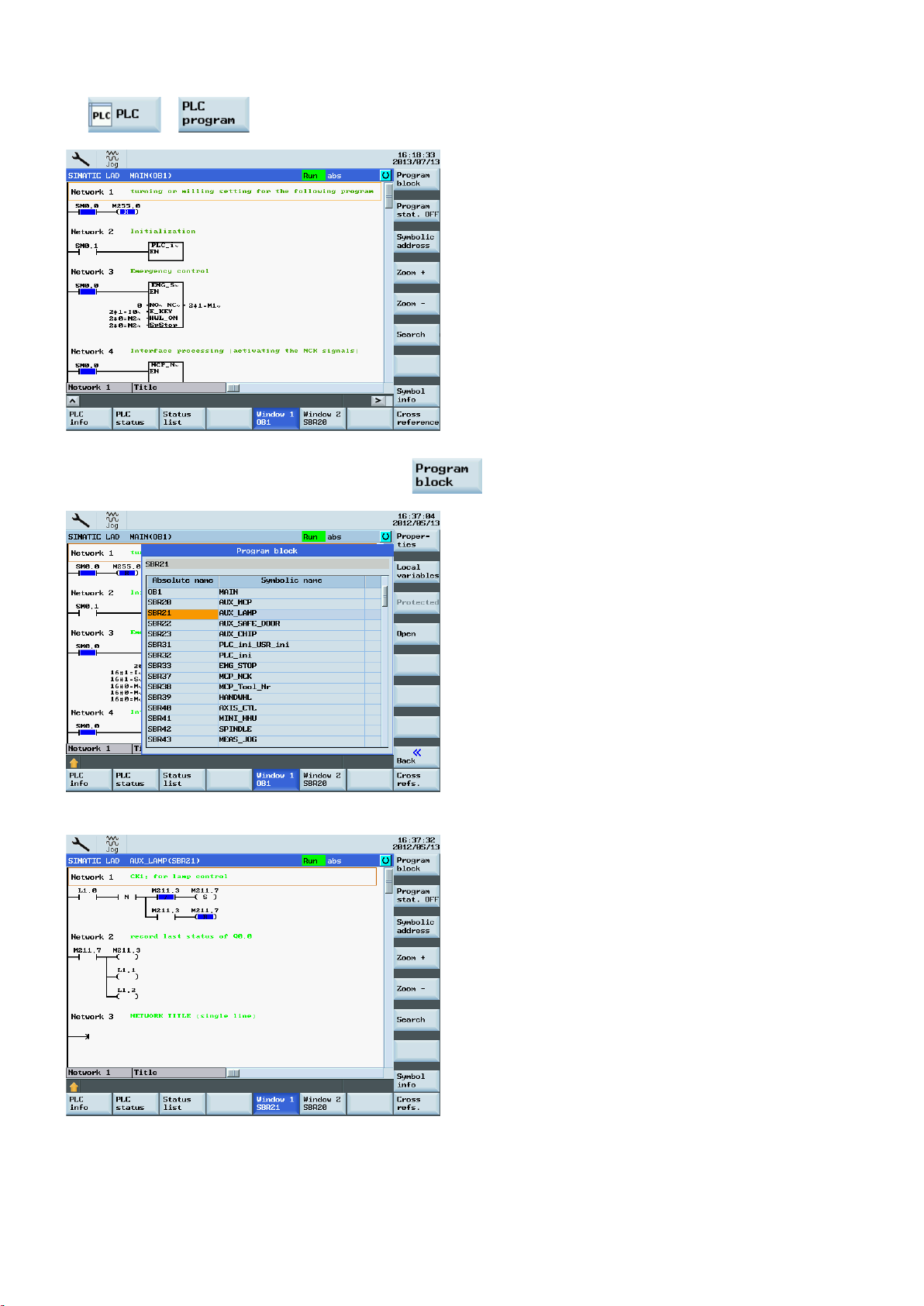
You can view the status of the main program or use the softkey to view the status of a subroutine.
Two windows are available for you to view the program.
PLC Subroutines Manual
12 6FC5397-0FP40-0BA0, 08/2013

Testing and monitoring a PLC program with the PLC Programming Tool
2.6
Establishing a connection with the RS232 interface
Operating sequence to make an RS232 connection to the control
You can also view the status of your PLC program with the PLC Programming Tool:
1. Establish the communication between the SINUMERIK 808D ADVANCED and the PLC Programming Tool.
There are three methods for establishing the communication between the SINUMERIK 808D ADVANCED and the PLC
Programming Tool:
– Establishing a connection with the RS232 interface (Page 13)
– Establishing a direct connection with the Ethernet interface (Page 17)
– Establishing a network connection with the Ethernet interface (Page 20)
2. Use the menu command → to view the status of a PLC signal. You can also first click the status
chart symbol
and then click the symbol to view the status.
You can establish a communication between the control system and the PC/PG via the RS232 interface.
1. Connect the control system with the PC/PG using an RS232 cable.
2. Select the desired operating area on the PPU.
+
PLC Subroutines Manual
6FC5397-0FP40-0BA0, 08/2013
13

● 115.2 kbps
via the RS232 interface is active.
→
3. Press these two softkeys in succession to open the following communication setting window.
4. Use this softkey to select a communication baud rate. The SINUMERIK 808D ADVANCED
supports the following baud rates:
● 9.6 kbps
● 19.2 kbps
● 38.4 kbps
● 57.6 kbps
Operating sequence to configure communications in the PLC Programming Tool
5. Activate the RS232 connection with this softkey.
No modifications to the settings are possible in this state.
The active or inactive state is retained even after a power-on (except when starting with the
default data).
In the lower right corner of the screen, the
1. Start the PLC Programming Tool on your PC/PG, and click this button in the navigation bar to
open the following dialog:
icon shows that the connection to the PG/PC
PLC Subroutines Manual
14 6FC5397-0FP40-0BA0, 08/2013

Alternatively, you can call the above dialog by double clicking the
icon in the
project tree or choosing from the main screen menu:
2. Double-click the access point symbol.
Then the following "Set PG/PC Interface" dialog is displayed.
PLC Subroutines Manual
6FC5397-0FP40-0BA0, 08/2013
Check the PG/PC interface being used. For RS232 communication, you must assign the
interface "PLC802(PPI)" to the PLC programming tool.
15
NOTE
Double click this icon on the right side of the communication setting window. It will take several
stem is identified as follows, and then the
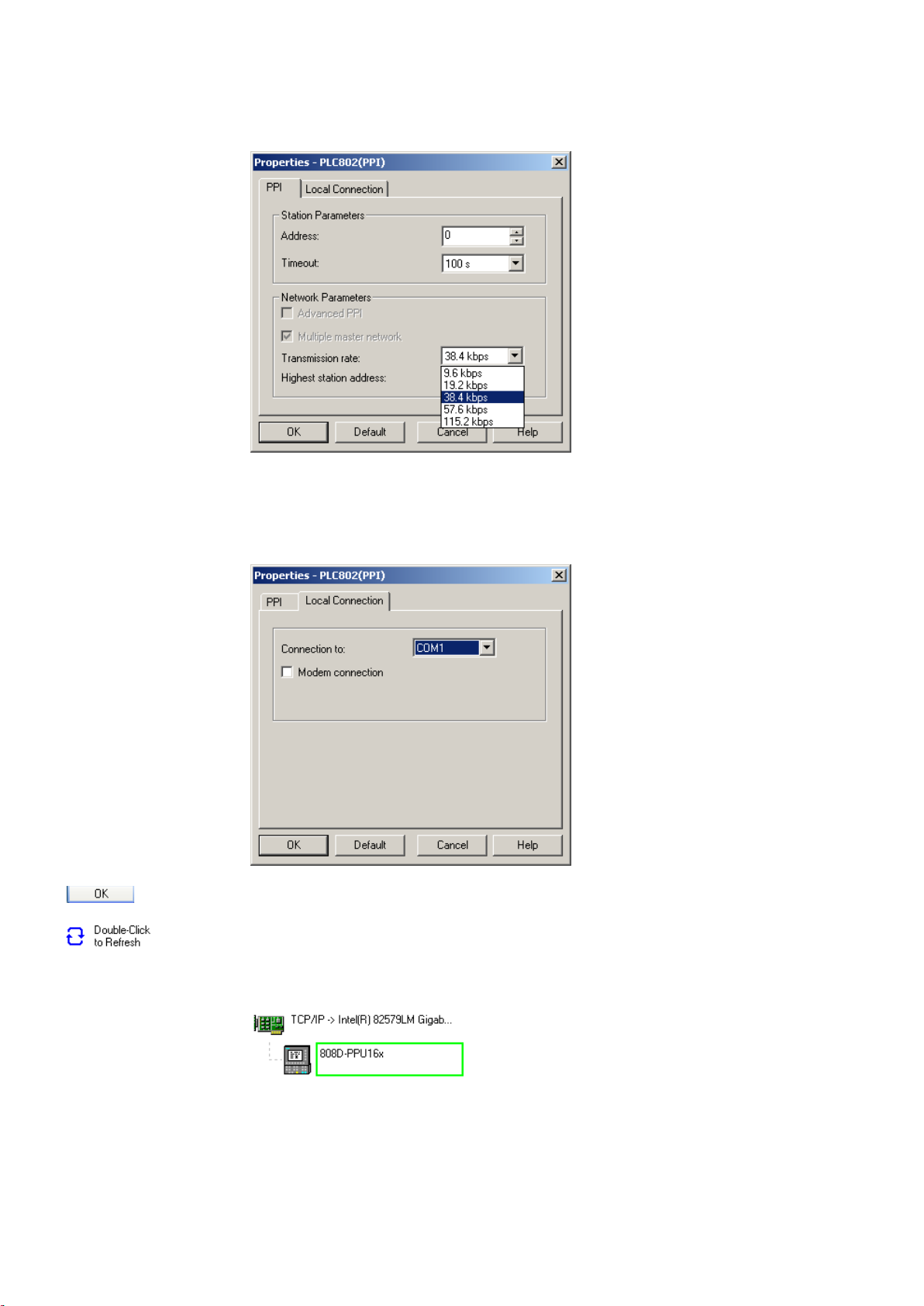
3. Double click the interface "PLC802(PPI)" or click the context menu "Properties", and the
following property dialog is displayed.
On the "PPI" tab page, set the baud rate for the transmission rate, which the PLC
Programming Tool will use for communication.
: The baud rate you select must be the same as what you have set on the control.
4. Open the "Local connection" tab to specify the COM port to which the RS232 (V24) cable is
connected.
5. Click this button twice to exit the "Set PG/PC Interface" dialog.
6.
minutes to search for a valid address.
7. Wait until the information on the connected control sy
connection is ready.
PLC Subroutines Manual
16 6FC5397-0FP40-0BA0, 08/2013
Note
2.7
Establishing a direct connection with the Ethernet interface
Operating sequence to enable an Ethernet peer-to-peer connection to the control
Before configuring communications in the PLC Programming Tool, make sure the connection is already enabled on the
control.
You can establish a direct connection between the control system and the PC/PG via the Ethernet interface.
1. Connect the control system with the PC/PG using an Ethernet cable.
2. Select the desired operating area on the PPU.
+
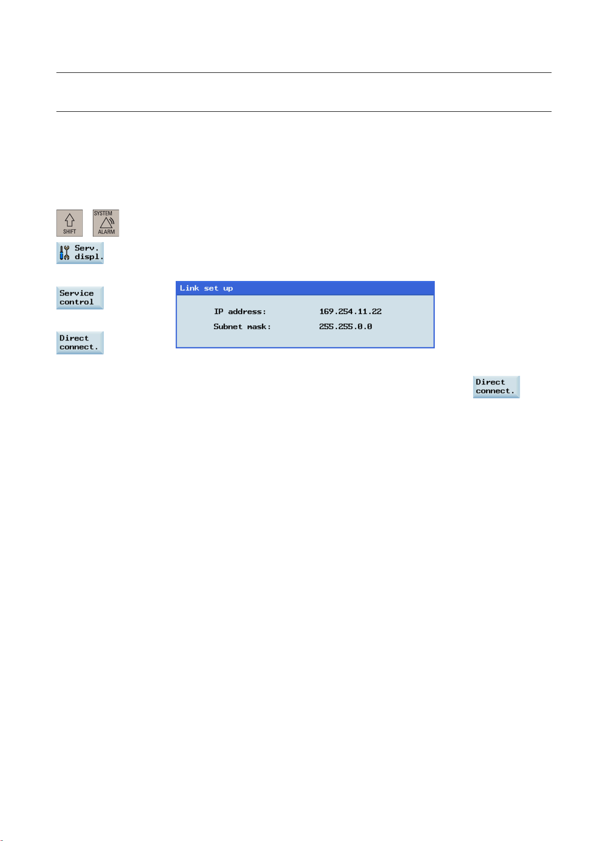
3. Set up a direct connection on the control system by pressing these three softkeys in
→
→
succession.
The following dialog pops up:
The IP address and subnet mask shown are fixed values.
These values cannot be changed.
You can cancel the Ethernet peer-to-peer connection once more using the
softkey.
PLC Subroutines Manual
6FC5397-0FP40-0BA0, 08/2013
17

Operating sequence to configure communications in the PLC Programming Tool
→
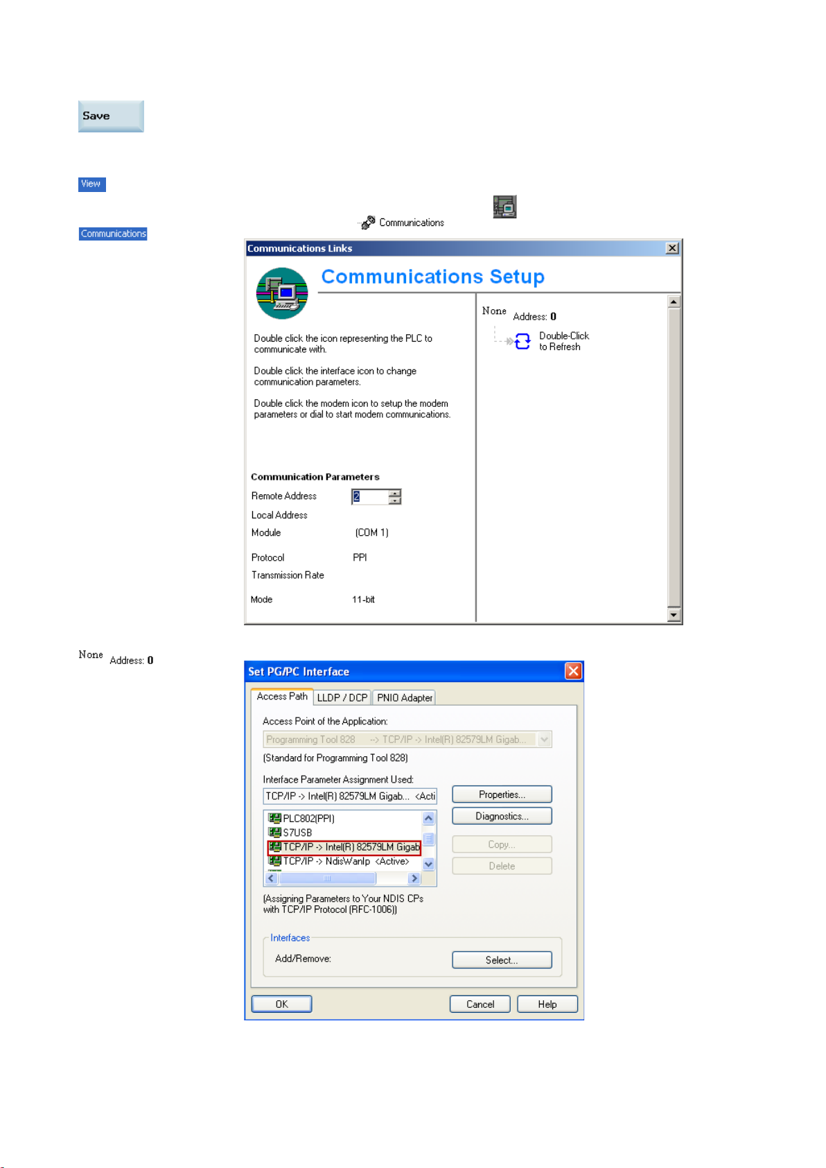
1. Choose these two menus from the menu bar to open the following communication setting
window.
Also you can click the communication button
communication icon
in the project tree to display the window.
in the navigation bar, or click the
2. Double click this icon on the right side. Then the following interface setting dialog is displayed.
PLC Subroutines Manual
18 6FC5397-0FP40-0BA0, 08/2013

corresponding SINUMERIK 808D ADVANCED control, which is previously displayed in the link
Note
Select the TCP/IP pointed to the Ethernet card of your PC, and then click the
button.
You can find the name of your Ethernet card under "Start" > "Settings" > "Network
connections" on your PC.
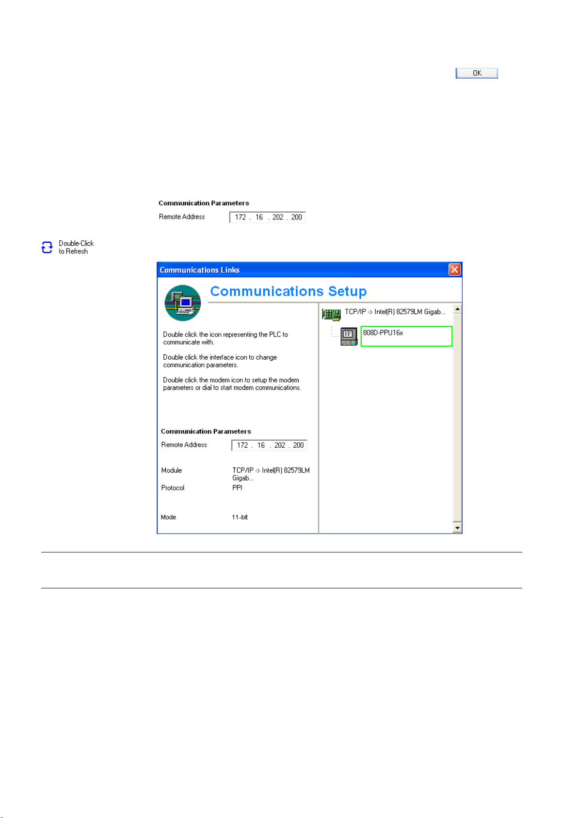
3. On the left side of the communication setting window, enter the IP address for the
setting dialog on the control, as shown below.
4. Double click this icon on the right side of the communication setting window to establish a
connection to the specified IP address.
● Before configuring communications in the PLC Programming Tool, make sure the connection must be already enabled
on the control.
● Ensure that the IP address of your PC and the IP address of the control exist in the same network segment.
PLC Subroutines Manual
6FC5397-0FP40-0BA0, 08/2013
19

2.8
Establishing a network connection with the Ethernet interface
Operating sequence to enable an Ethernet network connection to the control
Note
Yes
No
ues for the IP address and
You can establish a network connection between the control system and the PC/PG via the Ethernet interface.
1. Connect the control system with the local network using an Ethernet cable.
2. Select the desired operating area on the PPU.
+
3. Press these two softkeys in succession to enter the service control window.
→
4. Press this softkey to enter the window for network configuration.
: In this case, make sure the following vertical softkey is deselected.
5. Configure the network as required in the following window.
You can configure the DHCP with the
● If you select "
assigned.
● If you select "
subnet mask. The IP address here must be within the same network segment with the IP
address of your PC.
" for the DHCP, the IP address and subnet mask will be automatically
" for the DHCP, you must manually enter the val
hardkey.
PLC Subroutines Manual
20 6FC5397-0FP40-0BA0, 08/2013
Yes
Operating sequence to configure communications in the PLC Programming Tool
6. Press this softkey to save the configuration. If you select "
restart the control system to activate the network configuration.
1.
→
Choose these two menus from the menu bar to open the following communication setting
window.
Also you can click the communication button
communication icon
in the project tree to display the window.
" for the DHCP, you need to
in the navigation bar, or click the
2. Double click this icon on the right side. Then the following interface setting dialog is displayed.
PLC Subroutines Manual
6FC5397-0FP40-0BA0, 08/2013
21
Yes
No
Note
2.9
PLC application Download/Upload/Copy/Compare
PLC project
.pte
.pte
3. On the left side of the communication setting window, enter the IP address for the
Select the TCP/IP pointed to the Ethernet card of your PC, and then click the
button.
You can find the name of your Ethernet card under "Start" > "Settings" > "Network
connections" on your PC.
corresponding SINUMERIK 808D ADVANCED control.
● When you select "
automatically assigned.
● When you select "
previously entered on the control manually.
4. Double click this icon on the right side of the communication setting window to establish a
connection to the specified IP address.
" for the DHCP on the control, enter the IP address that is already
" for the DHCP on the control, enter the IP address that you've
● Before configuring communications in the PLC Programming Tool, make sure the connection must be already enabled
on the control.
You can save, copy or over-write a PLC project or PLC application on the control system by using the following:
● PLC Programming Tool
● USB stick
The
You can upload / download a PLC project from / to the control system with the PLC Programming Tool. Also with this tool,
you can import and export the PLC project in the "
format from / to a USB stick directly on the control system.
PLC Subroutines Manual
contains the PLC user program, including all of the important information (symbols, comments, ...).
" format. Additionally, you can read / write the PLC project in the "
"
22 6FC5397-0FP40-0BA0, 08/2013

Download
● Establishing a network connection with the Ethernet interface (Page 20)
You can write the transferred data into the permanent memory (load memory) of the control system with the PLC
Programming Tool or a USB stick.
To download a PLC application with the PLC Programming Tool, proceed as follows:
1. Establish the communication between the control and the PLC Programming Tool.
You can establish the connection by using the following three methods:
● Establishing a connection with the RS232 interface (Page 13)
● Establishing a direct connection with the Ethernet interface (Page 17)
→
2.
Choose these two menus from the menu bar or click the download icon to start the download,
and the download dialog pops up:
PLC Subroutines Manual
6FC5397-0FP40-0BA0, 08/2013
23
Loading...