


8DJ20
www.siemens.com/energy
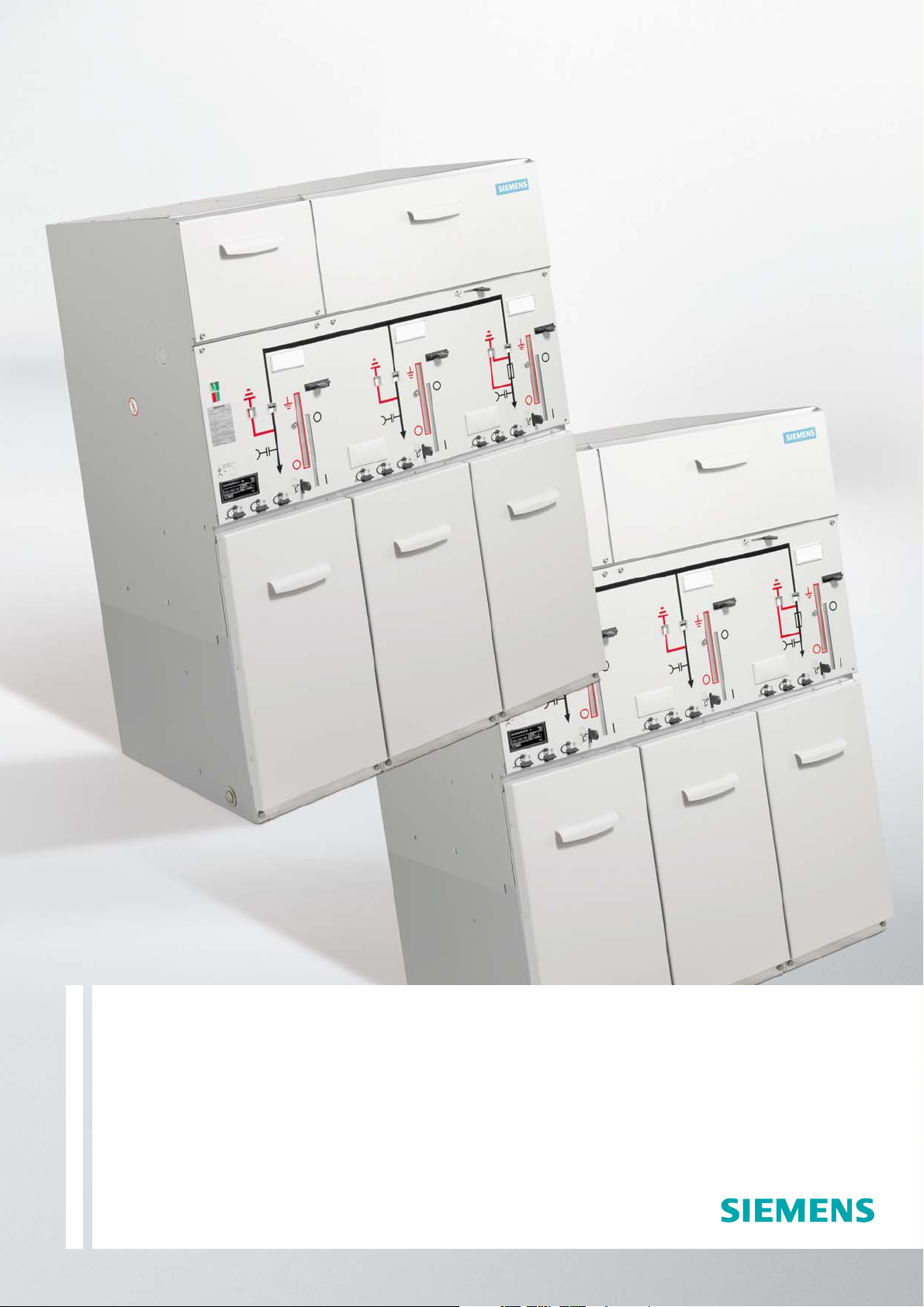
Switchgear Type 8DJ20
up to 24 kV, Gas-Insulated
Medium-Voltage Switchgear
Catalog HA 45.31 · 2008

Switchgear Type 8DJ20 up to 24 kV, Gas-Insulated· Siemens HA 45.31 · 2008
2
8DJ20 switchgear is a factory-
assembled, type-tested, metal-
enclosed switchgear for indoor
installation.
Typ ic al us es
8DJ20 switchgear is used for
power distribution in substations
– even under severe environmen
-
tal conditions, such as:
•
Industrial environments
•
Damp, sandy or dusty areas
•
Simple outdoor substations
Main uses
•
Compact substations
•
Compact transformer substations,
e. g. for wind power stations
•
Garage and vault substations
•
Underground and underfloor
substations
•
Sidewalk substations, e.g.
containing switchgear with a
very small overall width – in
particular the basic versions
of schemes 10, 32 and 71 –
in conurbations
•
Substations with control aisle
Technology
•
Switchgear design with up to
5 feeders
•
Maintenance-free
•
Climate-independent
•
Partition class: PM
(metallic partition)
•
Three-pole primary enclosure,
metal-enclosed
•
Insulating gas SF
6
•
Welded switchgear vessel with-
out seals, made of stainless
steel, with welded-in bushings
for electrical connections and
mechanical components
•
Three-position switch-discon
-
nector with load-break and
make-proof earthing function
•
Cable connection for
bushings with outside cone
•
Connection with cable plugs
– In ring-main feeders with
bolted contact (M16)
– In transformer feeders with
plug-in contact
•
Option: Connection with
conventional sealing ends
– For thermoplastic-insulated
cables via elbow adapter
AKE 20/630 (make Siemens)
– For paper-insulated mass-im-
pregnated cables via commer-
cially available adapter systems
•
Easy installation
Personal safety
•
Safe-to-touch and hermetically-
sealed primary enclosure
•
HV HRC fuses and cable sealing
ends are only accessible when
outgoing feeders are earthed
•
Operation only possible when
enclosure is closed
•
Logical mechanical interlocking
•
Capacitive voltage detecting
system to verify safe isolation
from supply
•
Feeder earthing by means of
make-proof earthing switches
Security of operation
•
Hermetically-sealed primary
enclosure independent of en-
vironmental effects such as
pollution, humidity and small
animals – sealed for life:
– Welded switchgear vessel
– Welded-in bushings and
operating mechanism
•
Operating mechanism parts
maintenance-free
(IEC 62 271-1/VDE 0671-1)
•
Operating mechanisms of
switching devices located out-
side the switchgear vessel
(primary enclosure)
•
Switchgear interlocking system
with logical mechanical inter-
locks
Cost-efficiency
Extremely low “life-cycle costs”
throughout the entire product
service life as a result of:
•
Maintenance-free concept
•
Climatic independence
•
Minimum space requirements
•
Maximum availability
Standards
seepage21
Technical Data
Electrical data, filling pressure, temperature 4
Application, Requirements
Features, typical use 2 and 3
Product Range
Equipment features 4
Product range overview, schemes 5
Design
Panel design 6
Dimensions
Switchgear 10 to 13
Floor openings, fixing points 14 and 15
Examples for cable connection 16
Designs, Special Designs
LV compartment, outdoor enclosures 18 to 20
Standards, Notes
Standards, specifications,
guidelines, classification 21 to 23
Shipping
Types of transport, transport data 17
Components
Three-position switch-disconnector,
operating mechanisms 7
HV HRC fuse assembly, secondary
equipment, pressure absorber system 8
Cable connection 9
For further information, please refer to
•
Catalog HA 40.1:
Switchgear Types 8DJ and 8DH, General Part
•
HA 45.31/41.11:
Supplements to Switchgear Types 8DJ and 8DH
Invalid:
Catalog HA 45.31 · 2006
The products and systems describedin this catalog
are manufactured and sold according to a certified
quality and environmental managementsystem
(acc. to ISO 9001 and ISO 14001).
(DQS Certificate Reg. No. DQS 003473 QM UM).
The certificate is accepted in all IQNet countries.
Contents
Application, Requirements
Features
© Siemens AG 2008
Page
Switchgear Type 8DJ20 up to 24 kV, Gas-Insulated· Siemens HA 45.31 · 2008
3
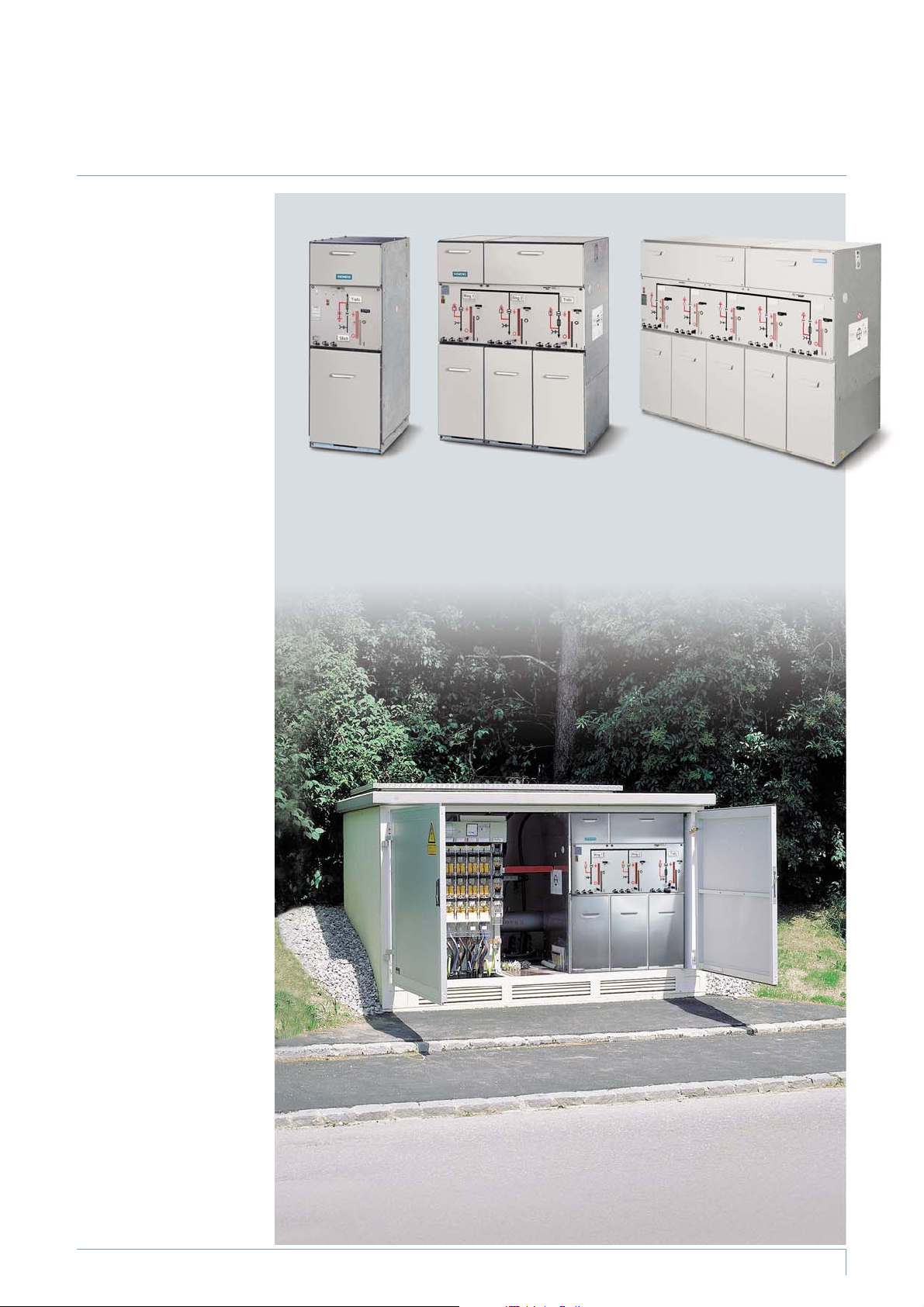
Our product range extends from
switchgear installed in a radial
transformer panel (individual
panel) to switchgear with 5
feeders, consisting of
•
Ring-main feeders
•
Transformer feeders with
HV HRC fuse assemblies
•
Circuit-breaker feeders (for
thecompleteproductrange
see Supplements to Catalogs
HA 45.31/41.11 – 2006)
The switchgear is available in
three overall heights:
•
1200 mm
(with low subframe)
•
1400 mm and 1760 mm
(with high subframe)
These overall heights cover all
areas of application, from com-
pact substations to switchgear
rooms with control aisle.
Basic design
•
Manual operating mechanism
•
Transformer cable connection
at the front (standard)
•
With logical mechanical inter-
locks
•
With ready-for-service indicator
•
With capacitive voltage de-
tecting system at the ring-
main feeders
Options (others on request)
•
Capacitive voltage detecting
system at the transformer
feeders
•
Motor operating mechanisms
for the three-position switch-
disconnectors
•
Auxiliary switch for three-posi-
tion switch-disconnector and
make-proof earthing switch
•
Short-circuit indicator with
built-in housing
•
Surge arresters for ring-main
feeders
•
Shunt releases for transformer
feeders
•
Secondary equipment for
remote operation or remote
indication, e.g. with local-
remote switch in the case of
motor operating mechanisms
or ”tripped signal” in the case
of transformer feeders
•
Locking devices
•
Closing lock-out
•
De-earthing lock-out
•
Cable clamps
Radial transformer
panel
1 transformer feeder
1 radial cable connection
Scheme 01
Ring-main/
transformer block
2 ring-main feeders
1 transformer feeder
Scheme 10
Ring-main/
transformer block
3 ring-main feeders
2 transformer feeders
Scheme 82
R
-
H
A
4
5
-
0
9
9
c
e
p
s
R
-
H
A
4
5
-
1
0
0
b
e
p
s
R
-
H
A
4
5
-
1
0
1
c
e
p
s
R
-
H
A
4
5
-
0
8
6
c
e
p
s
8DJ20 switchgear in
a compact substation
Typical use
Features
Application
Switchgear Type 8DJ20 up to 24 kV, Gas-Insulated· Siemens HA 45.31 · 2008
4
• Basic equipment
°
Additional equipment
(option), further
additional equipment
on request
xNot
applicable
– Not avail-
able
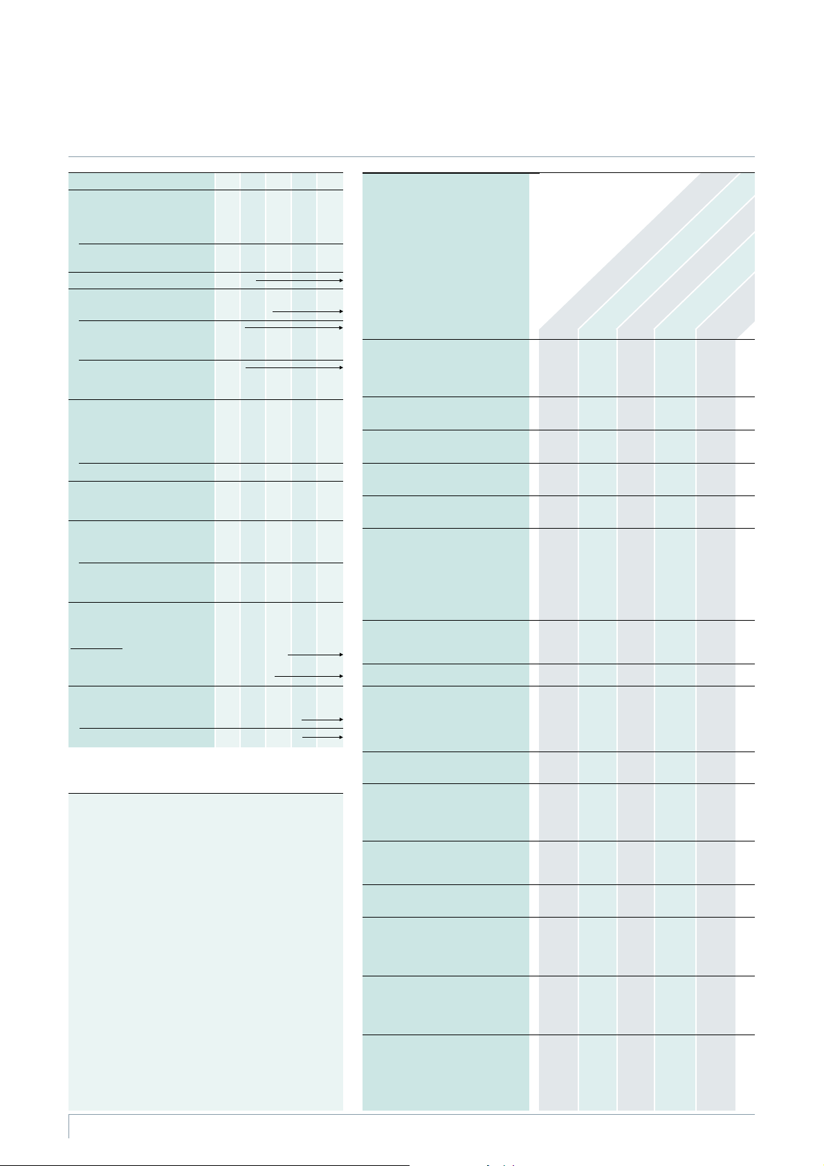
Equipment
Manual operating mechanism for
three-position switch-disconnector:
– As spring-operated mechanism
– As spring-operat./stored-energy mech.
Motor operating mechanism for
three-position switch-disconnector
Interlock for cable compartment
cover
Cable compartment cover locked
in place/screwed on
Cable bracket
2)
in ring-main and cable
feeders, cable routing downwards
Cable bracket in transformer feeder:
For cable routing
– Downwards (standard), f. cable elb. plugs
or
– Downwards, for straight cable plugs
or
– To the rear, for cable elbow plugs
Low-voltage terminals in the
operating mechanism
(option for secondary equipment)
Shunt release
Auxiliary switch for
– Switch-disconnector
CLOSED/OPEN:1NO+2NC
–EARTHINGCLOSED/OPEN:
1NO+1NC
Locking device for
three-position switch-disconnector
Short-circuit or earth-fault indicator
– Wiring at the indicator
(standard)
– Wiring to terminal (option)
De-earthing lock-out for
make-proof earthing switch
in transformer feeder
Closing lock-out for
three-position switch-disconnector
Double cable connection for
– Overall height of switchgear 1200 mm
– Overall height of switchgear 1400 mm
– Overall height of switchgear 1760 mm
Surge arrester for
– Overall height of switchgear 1200 mm
– Overall height of switchgear 1400 mm
– Overall height of switchgear 1760 mm
Cable clamps for cable fixing
– Supplied separately
– Preassembled (option)
Radial cable connection, panel K(E) for scheme 21
(with additional earthing switch)
Radial cable connection,panelKforscheme02
(without earthing switch)
Ring-main feeders
panel RK
Transformer feeder
panel1Tinscheme01
Transformer
feeders
panel T
1) According to some national requirements, higher values of the
rated short-duration power-frequency withstand voltage
available for I
k
=20kAwith:
– 42 kV for phase-to-phase, phase-to-earth and opencontact
gap as well as
– 48 kV across the isolating distance
Higher values of the rated lightning impulse withstand voltage:
– 95 kV for phase-to-phase, phase-to-earth and opencontact
gap as well as
– 110 kV across the isolating distance
2) For overall height of switchgear 1200 mm:
Cable bracket below the feeder
3) Cable fixing by customer
(the switchgear is supplied without cable bracket)
4) In case of scheme 01 the cable compartment cover is bolted.
The transformer connection is effected via the bushings
arranged underneath the switchgear vessel. The transformer
feeder is earthed by the three-position switch
5) Temperature range, reduced normal currents at ambientair
temperatures>+40°C
6) SurgearrestertypeRDAwithRICS(TycoElectronics)not
possible for a height of 1200 mm
o. r. = on request
•
–
x
x
•
–
–
•
–
•
–x
°°°
•
–•••
–•–––
••••
x
x
x
x
x
x
x
x
x
x
x
•
without
3)
•
•
without
3)
•–•••
–––
°°
°
°
x
x
°
°
°
°
°
°
°
x
°°°
°
°
°
°
°
°
–
–
–
–
°
xxx
4)
°
–x
°
––
°
°
°
°
°
°
°
°
°
x
x
x
x
x
x
–
°
°
–
°
°
o. r.
6)
°
°
x
x
x
x
x
x
°
°
°
°
°
°
°
–
°
°
Rated voltage U
r
kV 7.2121517.524
Rated insulation level
Rated short-duration kV
power-frequency
withstand voltage U
d
20 28
1)
36 38 50
Rated lightning impulse kV
withstand voltage U
p
60 75
1)
95 95 125
Rated frequency f
r
50/60 Hz
Rated normal current I
r
for ring-main feeders 400 or 630 A
for transformer feeders
depending on the
HV HRC fuse link
200 A
for schemes 01 and 21
depending on the
HV HRC fuse link
200 A
Rated short-time
withstand current I
k
at 1 s kA
kA
kA
–
20
25
–
20
25
–
20
25
16
20
25
16
20
–
at 3 s (option) kA 20 20 20 20 20
Rated peak kA
withstand current I
p
kA
kA
–
50
63
–
50
63
–
50
63
40
50
63
40
50
–
Rated short-circuit
making current I
ma
fortransformerfeeders kA2525252525
for ring-main feeders kA
kA
kA
–
50
63
–
50
63
–
50
63
40
50
63
40
50
–
Ambient air temperature T
(operating conditions acc. to
IEC 62 271-200/Clause 2 or
IEC 62 271-1
)
– Without secondary equipment
– With secondary equipment,
class “Minus 5 indoor”
-40to+70°C
5)
-5to55°C
5)
Pressure values at 20 °C
for the insulation:
Rated filling level p
re
1500 hPa (absolute)
Minimum functional level p
me
1300 hPA (absolute)
Technical Data, Product Range
Electrical data, temperature, filling pressure Equipment features of panels
Switchgear Type 8DJ20 up to 24 kV, Gas-Insulated· Siemens HA 45.31 · 2008
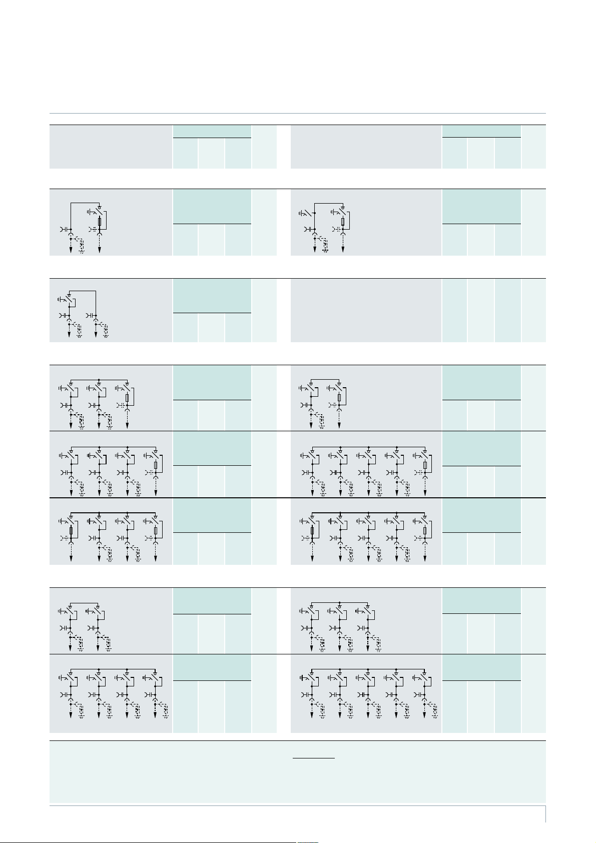
5
K Radial cable
connection as
infeed
K(E) Radial cable
connection, K as
K(E) with make-proof
earthing switch
Radial transformer panels
Scheme 01 * 1 transformer feeder,
1 radial cable connection
(Abbreviation 1T)
510 775 1200
1400
1760
140
160
200
Radial panel
Scheme 02 1 ring-main feeder with
radial cable connection
(Abbreviation 1RK)
710 775 1200
1400
1760
150
170
210
Block versions, consisting of ring-main andtransformer feeders (with HV HRCfuse assembly)
Scheme 10
* 2 ring-main feeders,
1 transformer feeder
(Abbreviations 2RK+1T)
1060 775 1200
1400
1760
280
300
340
Scheme 71 * 3 ring-main feeders,
1 transformer feeder
(Abbreviations 3RK+1T)
1410 775 1200
1400
1760
340
360
400
Scheme 81 * 2 ring-main feeders,
2 transformer feeders
(Abbreviations 2RK+2T)
1410 775 1200
1400
1760
400
420
460
Block versions, consisting of ring-main feeders (withoutHV HRC fuse assembly)
Scheme 11 2 ring-main feeders
(Abbreviation 2RK)
710 775 1200
1400
1760
160
170
210
Scheme 70 * 4 ring-main feeders
(Abbreviation 4RK)
1410 775 1200
1400
1760
280
300
340
Scheme
Components shown in dotted
lines can be used optionally.
Overall dimensions Net
1)
weight
approx.
kg
Width
mm
Depth
2) 3)
mm
Height
mm
Scheme
Components shown in dotted
lines can be used optionally.
Overall dimensions Net
1)
weight
approx.
kg
Width
mm
Depth
2) 3)
mm
Height
mm
Scheme 21 1 radial cable connection,
1 transformer feeder
(Abbreviations 1K(E)+1T)
710 775 1200
1400
1760
200
210
250
Scheme 20 1 ring-main feeder,
1 transformer feeder
(Abbreviations 1RK+1T)
710 775 1200
1400
1760
200
210
250
Scheme 72 4 ring-main feeders,
1 transformer feeder
(Abbreviations 4RK+1T)
1760 775 1200
1400
1760
420
440
480
Scheme 82 3 ring-main feeders,
2 transformer feeders
(Abbreviations 3RK+2T)
1760 775 1200
1400
1760
470
500
540
Scheme 84 5 ring-main feeders
(Abbreviation 5RK)
1760 775 1200
1400
1760
350
380
420
Scheme 32
* 3 ring-main feeders
(Abbreviation 3RK)
1060 775 1200
1400
1760
210
230
270
1) Depending on the relevant equipment, e.g. motor operating mechanism
2) Additional wall distance required: W 15 mm
3) For cable routing of transformer cables downwards
* Scheme is also suitable for outdoor enclosure (see pages 18 and 19)
Abbreviations:
RK = Ring-main feeder K = Cable feeder T = Transformer feeder
K(E) = Cable feeder forradial cable connection with make-proofearthing switch
T
HA45-2294d eps
K
HA45-2295c eps
RK K
HA45-2296c eps
RK TRK
HA45-2302c eps
RK TRK RK
HA45-2304c eps
RK TRKT
HA45-2297c eps
RK RK
HA45-2301c eps
RK RKRK RK
RK RKRK RK RK
HA45-2306c eps
HA45-2300c eps
RK RKRK
HA45-2305c eps
RK TRKT RK
HA45-2303c eps
RK TRK RK RK
HA45-2298c eps
TRK
HA45-2299c eps
TK(E)
Product range overview, schemes
Product Range
Switchgear Type 8DJ20 up to 24 kV, Gas-Insulated· Siemens HA 45.31 · 2008
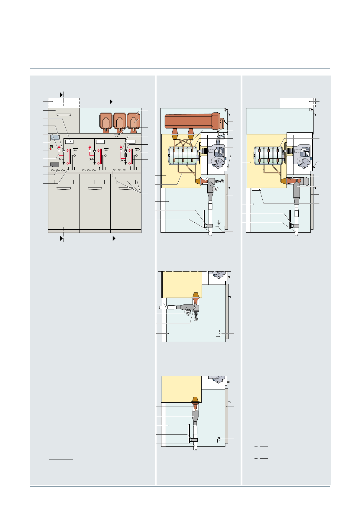
6
1 Niche for customer-side low-voltage equipment
2 Feeder designation label
Position indicators
in the ring-main feeder:
3 Load-break function ”CLOSED – OPEN”
4 Earthing function ”OPEN – EARTHED”
5 Rating and type plate
6 Ready-for-service indicator
7 Mimic diagram
8 Short-circuit/earth-fault indicator (option)
9 Sockets for voltage detecting system
10 Interlock of the cable compartment cover
11 HV HRC fuse assembly, cover removed
12 Handle for replacing the HV HRC fuse link
13 Interlock for HV HRC fuse assembly
Position indicators
in the transformer feeder:
14 Earthing function ”OPEN – EARTHED”
15 Load-break function ”CLOSED – OPEN”
with ”HV HRC fuse tripped” or”shunt release
tripped”, where applicable
16 Locking device
(option for three-position switch-disconnector)
17 Manual operation for the mechanism of
the earthing function
Option
Cable connection for cable elbow
plugs, cable routing tothe rear
(cable fixing by customer)
18 Manual operation for the mechanism of
the load-break function
19 Switchgear vessel, filled with gas
20 Connecting bar to cable connection
21 Arrangement of cable connections
22 Cable compartment
23 Cable bracket
24 Cable (not included in the scope ofsupply)
25 Cover of the HV HRC fuse compartment
26 Connecting bar to the bushings
for the HV HRC fuse
27 Three-position switch-disconnector
28 Spring-operated/stored-energy mechanism
29 Bushing as interface type “A” for
cable plug with plug-in contact
O
ption: Bushing as interface type “C”
for cable plug with bolted contact (M16)
30 O
ption: Cable elbow plug with
plug-in contact
31 Cable compartment cover
32 M12 earthing connection
33 Spring-operated mechanism
34 Bushing as interface type “C“ for cable
plug with bolted contact (M16)
35 O
ption: Cable T-plug with bolted contact
36 Pressure relief device
37 O
ption: Straight cable plug with
plug-in contact
38 O
ption: Low-voltage compartment
HA45-2337d eps
L1 L2 L3
5
3
2
1
4
B
A
B
A
6
7
8
9
10
11
12
13
14
15
17
18
19
20
21
22
23
24
25
26
27
28
10
19
20
31
22
23
32
24
27
33
31
36
10
16
30
29
34
35
38
38
HA45-2308e eps
31
32
29
24
30
22
HA45-2309e eps
31
32
29
22
23
24
37
Ring-main/transformer block
Standard
Cable connection for cable elbowplugs
(option: for cable T-plugs),
cable routing downwards
Scheme 10
Transformer feeder
Section A-A
Cable connection with bolted contact (M16):
– For cable T-plug or cable elbow plug
– For conventional cable sealing ends via
elbow adapter AKE 20/630
Option
Cable connection for
straight cable plugs,
cable routing downwards
Ring-main feeder
Section B-B
Personal safety
All feeder-related covers can only be
opened if the associated three-position
switch-disconnector has been switched to
the “EARTHED” position.
Design
Panel design (example)
Switchgear Type 8DJ20 up to 24 kV, Gas-Insulated· Siemens HA 45.31 · 2008
7
Three-position
switch-disconnector
The switching device used
is the proven three-position
switch-disconnector
Functions
•
Load-break function
•
Earthing function with
short-circuit making capacity
•
Switch positions
CLOSED – OPEN – EARTHED
Operating mechanisms
The three-position switch-
disconnector is operated from
the switchgear front via
Detachable lever mechanism
(standard)
• Spring-operated mechanism
– With ”spring-operated
CLOSED” and ”spring-oper-
ated OPEN” for installation
in ring-main feeders
•
Spring-operated/stored-
energy mechanism
– With ”spring-operated
CLOSED” and ”spring-oper-
ated OPEN” for installation
in transformer feeders
–Withanadditionalenergy
store for the function ”stored-
energy OPEN” after tripping
by the HV HRC fuse (striker
tripping) or by the shunt
release
O
ptions
•
Motor operating mechanism
for switch-disconnector
•
Rotary operating mechanism
•
Locking devices
•
Auxiliary contacts for three
-
position switch-disconnector
and make-proof earthing
switch
•
Shunt release for transformer
feeders
•
Closing lock-out for ring-
main feeders
•
De-earthing lock-out for
transformer feeders
•
Different operating levers
1)
for
the operating mechanisms of
the switch-disconnector and of
the make-proof earthing switch
Three-position switch-disconnector
R
-
H
A
4
5
-
1
0
2
e
p
s
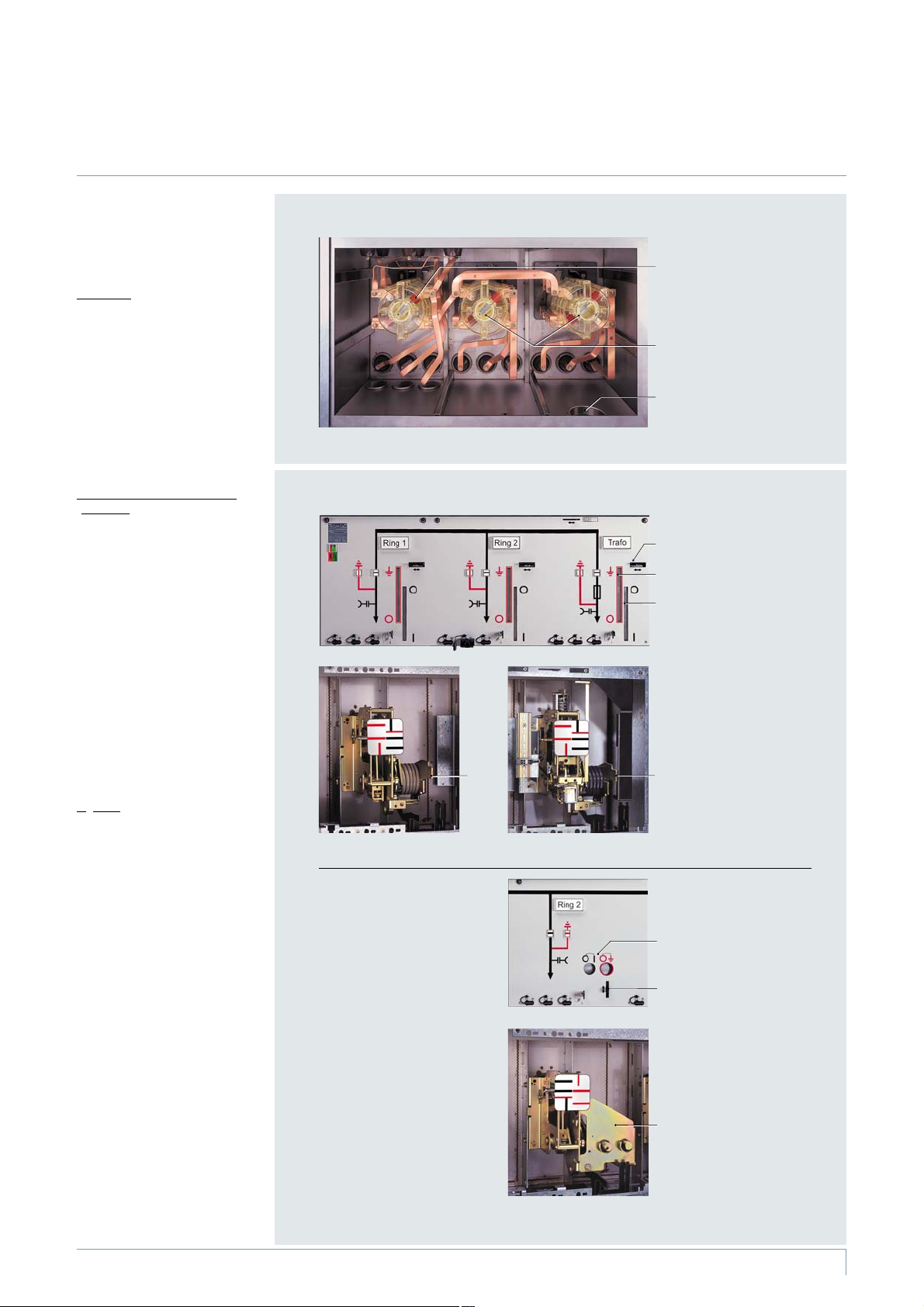
Operating mechanisms
Switchgear vessel of a
ring-main/transformer
block, scheme 10
(rear view)
1 Three-position switch-
disconnector in the
transformer feeder
2 Three-position switch-
disconnector in the
ring-main feeders
3 Pressure relief device
Control board for detach-
able lever mechanisms
(standard)
Example:
Ring-main/transformer block,
scheme 10
4 Locking device (option)
for the detachable lever
mechanism
5 Detachable lever
operation for the
earthing function
6 Detachable lever
operation for the
load-break function
7 Detachable lever
mechanism for the
ring-main feeder
8 Detachable lever
mechanism for the
transformer feeder
Control board for rotary
operating mechanisms
(option)
Example: Ring-main feeder
9 Symbols for the actuating
direction of the rotary
operating mechanism
10 Locking device for the ro-
tary operating mechanism
R
-
H
A
4
5
-
1
0
3
a
e
p
s
R
-
H
A
4
5
-
1
0
4
e
p
s
R
-
H
A
4
5
-
1
0
5
e
p
s
R
-
H
A
4
5
-
1
0
6
a
e
p
s
R
-
H
A
4
5
-
1
0
7
e
p
s
11 Rotary operating
mechanism (option)
10
1
11
2
3
9
4
5
6
8
7
1) According to VDN */VDEW**
recommendation
* AssociationofGermanNetwork
Operators VDN e.V. at the VDEW in
Germany (as of 2003)
** Association of German
Power Stations – VDEW e.V.
Three-position switch-disconnector, operating mechanisms
Components
Switchgear Type 8DJ20 up to 24 kV, Gas-Insulated· Siemens HA 45.31 · 2008
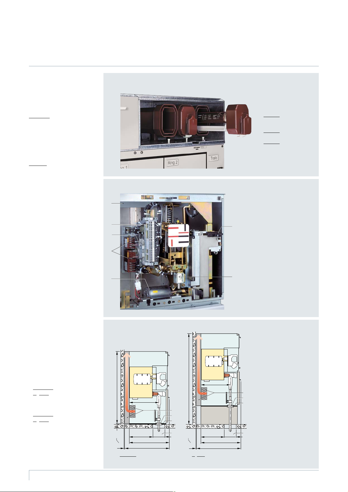
8
HV HRC fuse assembly
The HV HRC fuse boxes are
single-phase insulated and lo-
cated above the transformer
feeder outside the switchgear
vessel.
Standards
(see page 21)
HV HRC fuse links with striker in
“medium” version according to
•
IEC 60 282-1
•
VDE 0670 Parts 4 and 402
•
DIN 43 625 main dimensions
Features
•
Requirements fulfilled as HV
alternating current switch-
fuse combination
•
Selection of HV HRC fuses for
transformers
•
For further features
see Catalog HA 40.1
Secondary equipment (option)
•
Auxiliary switches, motor
operating mechanisms or
shunt releases wired to a
terminal strip
•
Location of the terminal strip
next to the operating mecha-
nism module of the feeder
concerned
•
Customer-side cable routing
to the terminal strip from the
side or rear
Pressure absorber system
(option)
•
Maintenance-free
•
For all schemes (except radial
transformer panel, scheme 01)
•
For rated short-time with
-
stand current I
k
w 16 kA,
with IAC (internal arc
classification, see page 22)
•
With 105 mm deep pressure
relief duct for pressure relief
upwards
•
For overall height of switch-
gear:
–Standard:
1400 mm
–O
ption: 1760 mm
•
For wall-standing arrangement
•
Transformer cable routing:
–Standard:
Downwards
–O
ption: To th e r ear for
schemes 10, 71 and 72
•
Weight approx. 110 kg
HV HRC fuse compartment
HV HRC fuse compartment
with cable compartment
cover removed
Phase L1:
HV HRC fuse box with
HV HRC fuse slide removed
Phase L2:
HV HRC fuse box closed
Phase L3:
Replacement of HV HRC fuses
Auxiliary switch, motor
operating mechanism and
shunt release
Example: Transformer feeder
1 Wiring duct
2 Te rm ina l str ip
3 Auxiliary switch at spring-
operated mechanism of a
ring-main feeder
4 Auxiliary contactors
(standard for motor
operating mechanism)
5 Motor operating mechanism
at spring-operated/
stored-energy mechanism
6 Locking device
(standard for motor
operating mechanism)
7 Shunt release at spring-
operated/stored-energy
mechanism
Sectional views of the
pressure absorber system
1 Wall distance
2 Pressure absorber system
with rear pressure relief
duct directed upwards
3 Cable bushing
4 Divided floor plate for
cable entry for on-site
installation
5 Floor opening for the
cable feeder
HA45-2364 eps
1400
~2
880
³
15
775
240
435
~560
2
3
5
1
4
7
1
2
6
HA45-2363 eps
~1762
880
³
15
775
240
435
~560
5
1
2
3
4
R
-
H
A
4
5
-
1
0
8
e
p
s
R
-
H
A
4
5
-
1
3
3
e
p
s
3
4
5
Pressure absorber system
(option)
Standard: Overall height 1400 mm
O
ption: Overall height 1760 mm
Secondary equipment (option)
Components
HV HRC fuse assembly, secondary equipment, pressure absorber system
 Loading...