


 Loading...
|
|
|
|
|
|
|
|
|
© Siemens AG 2014 |
||
|
|
|
|
|
|
|
|
|
|
Glossary |
|
|
|
|
|
|
|
|
|
|
|
Functions and terms |
|
|
|
|
|
|
|
|
|
|
|
SINUMERIK 828 |
|
|
|
|
|
|
|
|
|
|
|
|
|
3D simulation, |
Required for enabling 3D view in part program simulation. 3D simulation can be viewed even in |
||||||||||
finished part |
real-time simulation. Without this option, it is possible to see 2D simulation (with different views) |
||||||||||
Option P25 |
in the system. |
||||||||||
Article No.: |
If simultaneous recording option already exists in the system, then it is possible to have 3D view |
||||||||||
6FC5800-0AP25-0YB0 |
during the real-time simulation. |
||||||||||
|
|||||||||||
|
|
|
|
|
|
|
|
|
|
|
|
Access |
|
|
|
|
|
|
|
|
PC/PG |
||
|
|
|
|
|
|
|
|
||||
MyMachine /P2P |
|
|
|
|
|
|
|
|
|
|
|
Option P30 |
|
|
|
|
|
|
|
|
|
|
|
|
|
|
|
|
|
|
|
|
|
|
|
|
|
|
|
|
|
|
|
|
|
|
|
Article No.: |
|
|
|
|
|
|
|
|
|
|
|
|
|
|
|
|
|
|
|
|
|
|
|
6FC5800-0AP30-0YB0 |
|
|
|
|
|
|
|
|
|
|
|
|
|
|
|
|
|
|
|
|
Modem router SINUMERIK 828D |
||
|
|
|
|
|
|
|
|
|
|
|
|
|
|
|
|
|
|
|
|
|
|
|
|
|
|
|
|
|
|
|
|
|
|
|
|
|
|
|
|
|
|
Analog ISDN |
|
|
PROFINET |
|||
|
|
|||||
G_NC01_EN_00582
RCS Host remote diagnostics software for connection of a modem router to the X127 is solely necessary in case of connection via Modem router. It is possible to monitor and influence a control from a remote PC. The remote viewer gets the same display of SINUMERIK 828. A modem router is required for connecting SINUMERIK 828 to a viewer on a telephone line /internet
Remote diagnosis has the following services:
Direct access to SINUMERIK 828
Data exchange (file transfer)
Advanced technology |
The following extended technologies are only available in SINUMERIK 828D BASIC. |
|
||||||
functions |
Asymmetric grooves (only turning) |
|
|
|
|
|
||
Option P58 |
Drill and thread milling |
|
|
|
|
|
||
Article No.: |
Thread milling |
|
|
|
|
|
||
6FC5800-0AP58-0YB0 |
Multi-edge milling |
|
|
|
|
|
||
|
|
|
|
|
|
|||
|
Engraving |
|
|
|
|
|
||
|
Extended stock removal along contour with segmentation of blank (only turning) |
|||||||
|
Contour grooving and plunge turning (only turning) |
|
|
|
||||
|
Milling of contour pockets and spigots (with up to 12 islands) |
|
||||||
|
Position pattern - hide position |
|
|
|
|
|
||
|
Asymmetrically turn a shoulder |
|
|
|
|
|
||
|
DIN thread undercut |
|
|
|
|
|
||
|
|
|
|
|
||||
Axis/spindle, each |
This option must be selected if the required number of interpolating axes/spindles is more than the |
|||||||
additional |
basic quantity of axes/spindles. The basic quantity of axes offered by panel processing units/ |
|||||||
Option |
SINUMERIK 828D family is given in the table below: |
|
|
|
||||
Article No.: |
|
|
|
|
|
|
|
|
|
|
SINUMERIK 828D |
|
SINUMERIK 828D |
|
|||
6FC5800-0AC20-0YB0 |
|
|
|
|
||||
|
|
|
BASIC |
|
|
|
|
|
(6FC5800-0AA00-0YB0 |
|
|
|
|
|
|
|
|
|
|
PPU 24x.3 |
|
PPU 26x.3 |
|
PPU 28x.3 |
||
for V 2.x) |
|
|
|
|
||||
|
Basic quantity of axes |
|
|
|
|
|
|
|
|
|
|
|
|
|
|
|
|
|
|
Turning |
|
3 |
|
3 |
|
3 |
|
|
|
|
|
|
|
|
|
|
|
Milling |
|
4 |
|
4 |
|
4 |
|
|
|
|
|
|
|
|
|
|
Max. possible quantity of |
|
|
|
|
|
|
|
|
axes/spindles |
|
|
|
|
|
|
|
|
|
|
|
|
|
|
|
|
|
|
Turning |
|
5 |
|
6 |
|
8 |
|
|
|
|
|
|
|
|
|
|
|
Milling |
|
5 |
|
6 |
|
6 |
|
|
|
|
|
|
|
|
|
Siemens NC 82 · 2014 |
1 |
|

© Siemens AG 2014
Glossary
Functions and terms
SINUMERIK 828
Contour handwheel
Option M08
Article No.: 6FC5800-0AM08-0YB0
|
When the contour handwheel function is activated, the handwheel has a velocity-generating |
|
|
effect in AUTOMATIC and MDI modes on all programmed traversing movements of the path and |
|
|
synchronized axes. |
|
|
A feedrate specified via the CNC program becomes ineffective and a programmed velocity profile is |
|
|
no longer valid. The feedrate, in mm/min, results from the handwheel pulses as based on pulse |
|
|
weighting (machine data) and the active increment. The handwheel's direction of rotation |
|
|
determines the direction of travel: |
|
|
Clockwise: |
|
|
in the programmed direction of travel (even beyond block boundaries) |
|
|
Counter-clockwise: |
|
|
against the programmed direction of travel (continuation beyond the start of the block is |
|
|
prevented). |
|
|
|
|
Evaluation of internal |
The following real-time drive variables can be accessed/evaluated in part program: |
|
drive variables |
$AA_LOAD drive capacity utilization in Percentage (%) |
|
Option S53 |
$AA_POWER drive active power in Watts (W) |
|
Article No.: |
$AA_TORQUE drive torque set point in Newton meters (Nm) |
|
6FC5800-0AS53-0YB0 |
$AA_CURR actual axis/spindle current in Ampere (A) |
|
|
||
(6FC5800-0AM41-0YB0 |
These variables can be used along with synchronized options |
|
These variables can be also read through PLC interface, NC variables DB1200.DBxxxxx. For the PLC |
||
for V 2.x) |
||
purpose, evaluation of internal drives is standard. |
||
|
||
|
Application examples : |
|
|
Evaluation of these drive variables also permits machines and tools to be protected from |
|
|
overloading, as well as shorter machining times and an improved surface quality for the |
|
|
workpieces to be achieved. Evaluation of internal drive variables is a prerequisite for implementing |
|
|
adaptive control (AC). |
|
|
Adaptive control can be parameterized within the part program as follows: |
|
|
Additive influence: The programmed feed value is corrected by adding. |
|
|
Multiplicative influence: The feed value is multiplied by a factor (override). |
|
|
|
|
Extended operator |
Number of levels for skip blocks 10 (default value 2) |
|
functions |
Teach-in function |
|
Option P16 |
Backup workpiece setup data |
|
Article No.: |
Display active synchronized actions |
|
6FC5800-0AP16-0YB0 |
DRF offset |
|
|
||
|
Overstoring |
|
|
Extended block search (program/search pointer, level up/down, interrupt position) |
|
|
Manual workpiece measurement: advanced strategies for part probing |
|
|
Additional measuring version beyond standard scope |
|
|
(standard scope workpiece zero: Set edge, align edge, right-angled corner, 1 hole, and 1 circular |
|
|
spigot. |
|
|
Expansion of the measurement window via combo box) |
|
|
Load/save MDI program |
|
2 |
|
|
Siemens NC 82 · 2014 |
|
|
|
|
|
|
|
|
|
|
Extended stop and retract ESR, driveautonomous
Option M60
Article No.: 6FC5800-0AM60-0YB0
Generic coupling Basic: CP-Basic
Option M72
Article No.: 6FC5800-0AM72-0YB0
© Siemens AG 2014
Glossary
Functions and terms
SINUMERIK 828
Power failure
retraction
Work-piece 00583
_EN
_G _NC01
A safe position is assumed from the machining level without any collision between tool and workpiece.
As well as the drive-autonomous stop and retract function, the CNC-controlled stop and retract functionality is also provided. To permit gentle interpolated retraction on the path or contour, the path interpolation can be processed further for a definable period following the triggering event. The retraction axes are subsequently traversed in synchronism to an absolute or incremental position as programmed.
These functions are primarily used for gearing and grinding technologies.
n2 |
n1 |
00575 |
|
|
G NC01 EN_ |
Spindle 1 |
Spindle 2 |
|
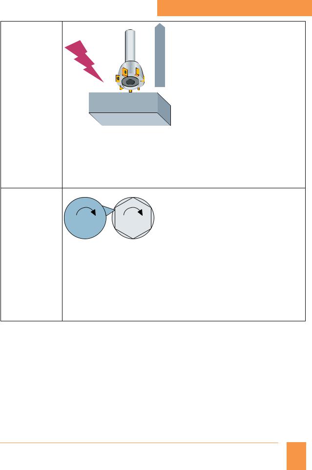
Up to 4 × simple coupled motion and
Up to 1 × synchronous spindles/multi-edge turning or master value coupling/curve table
interpolation or axial coupling in the machine coordinate system Application example:
Multi-edge machining (polygonal turning)
The synchronous spindle function provides the basis for multi-edge machining through specification of an integer gear ratio between leading spindle and following spindle. In the picture above, spindle 2 contains the job and spindle 1 has the cutting tool. Both the spindles are synchronized and run at a ratio (e.g.: 1:6), in order to get polygon shape on the job.
Siemens NC 82 · 2014 |
3 |
|
© Siemens AG 2014
Glossary
Functions and terms
SINUMERIK 828
Generic coupling Comfort: CP-Comfort
Option M73
Article No.: 6FC5800-0AM73-0YB0
Generic coupling Static: CP-Static
Option M75
Article No.: 6FC5800-0AM75-0YB0
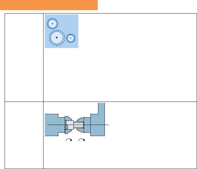
Up to 4 × simple coupled motion and
Up to 4 × synchronous spindle/multi-edge turning and/or master value coupling/curve table
interpolation and/or axial coupling in the machine coordinate system Also:
1 × electronic gear for up to 3 leading axes is possible (without curve table interpolation and without cascading)
Application example:
This option is suitable for the hobbing process. Gear hobbing machines are machines which have a rotating multiple-tooth cutting tool to produce teeth on helical gears, worm gears, cycloid gears, etc.
When two axes (e.g. tool axes) with different ratio must be coupled on to third axes (e.g. blank axes).
G_NC01_EN_00576
n1 |
n2 |
Spindle 2 |
Spindle 1 |
|
One simple synchronous spindle (with coupling ratio 1:1, no multi-edge machining)
Application example:
Reverse side machining in a double-spindle lathe with on-the-fly transfer of the work piece from the position-synchronous LS to the FS (or vice versa), without having to decelerate to standstill.
|
4 |
|
|
Siemens NC 82 · 2014 |
|
|
|
|
|
|
|
|
|
|

© Siemens AG 2014
Glossary
Functions and terms
SINUMERIK 828
Inclined axis |
JOG "X" |
|
|
Option M28 |
|
JOG "U" |
U |
Article No.: |
|
||
|
|
||
6FC5800-0AM28-0YB0 |
|
|
|
|
|
|
|
X |
|
|
|
|
|
|
G07 X70 Z40 F4000 |
100 |
|
|
G05 X70 F100 |
70 |
|
|
|
|
|
|
|
W |
0 |
40 |
Z |
|
|||
|
|
|
G_NC01_XX_00121 |
Oblique plunge-cut grinding: machine with non-Cartesian X axis (U)
The Inclined axis function is used for fixed-angle interpolation using an oblique infeed axis (used primarily in conjunction with cylindrical grinding machines). The axes are programmed and displayed in the Cartesian coordinate system.
Tool offsets and work offsets are also entered in the Cartesian system and transformed to the real machine axes.
For oblique plunge-cutting with G05, it is necessary to program the start position with G07.
Leadscrew error
compensation, Bi-directional compensation bidirectional:
Bidirectional threaded spindle error compensation
Option M54 |
|
Article No.: |
|
6FC5800-0AM54-0YB0 |
G_NC01_EN_00585 |
|
Bidirectional compensation is an expansion to the leadscrew error compensation function (LEC) or the measuring system error compensation function (MSEC). By contrast to LEC and MSEC, bidirectional compensation works in both directions.
The option supports price sensitive front-face and peripheral side machining applications on lathes without a mechanical Y axis.
Siemens NC 82 · 2014 |
5 |
|
Loading...