


Start-Up 08/2003 Edition
sinumerik
SINUMERIK 802C base line

SINUMERIK 802C base line
Start-Up
Technical Manual
Valid as from |
|
Control system |
Software version |
SINUMERIK 802C base line |
4 |
SINUMERIK 802C base line Control System
Installing the control system
Installing the Drives
Start-Up
Software Update
Technical Appendix
1
2
3
4
5
6
2003.08 Edition

SINUMERIK ® Documentation
Key to editions
The editions listed below have been published prior to the current edition.
The column headed “Note” lists the amended sections, with reference to the previous edition.
Marking of edition in the “Note” column:
A ... ... |
New documentation. |
B ... ... |
Unchanged reprint with new order number. |
C ... ... |
Revised edition of new issue. |
Edition |
Order No. |
Note |
2000.04 |
6FC5597-3AA20-0BP1 |
A |
2002.01 |
6FC5597-3AA20-0BP2 |
C |
2003.08 |
6FC5597-4AA21-0BP0 |
C |
Trademarks
SIMATIC®, SIMATIC HMI®, SIMATIC NET®, SIMODRIVE®, SINUMERIK®, and SIMOTION® are registered trademarks of SIEMENS AG.
Other names in this publication might be trademarks whose use by a third party for his own purposes may violate the registered holder.
Copyright Siemens AG 2003. All right reserved
The reproduction, transmission or use of this document or its contents is not permitted without express written authority. Offenders will be liable for damages. All rights, including rights created by patent grant or registration of a utility model, are reserved.
Exclusion of liability
We have checked that the contents of this document correspond to the hardware and software described. Nonetheless, differences might exist and we cannot therefore guarantee that they are completely identical. The information contained in this document is reviewed regularly and any necessary changes will be included in the next edition. We welcome suggestions for improvement.
© Siemens AG, 2003
Subject to technical changes without notice.
Siemens-Aktiengesellschaft. |
SINUMERIK 802S/802C base line |
Safety notices

 !
! 


 !
! 


 !
! 

Qualified person
This Manual contains notices intended to ensure your personal safety , as well as to protect products and connected equipment against damage. Safety notices are highlighted by a warning triangle and presented in the following categories depending on the degree of risk involved:
Danger
Indicates an imminently hazardous situation which, if not avoided, will result in death or serious injury or in substantial property damage.
Warning
Indicates a potentially hazardous situation which, if not avoided, could result in death or serious injury or in substantial property damage.
Caution
Used with safety alert symbol indicates a potentially hazardous situation which, if not avoided, may result in minor or moderate injury or in property damage.
Caution
Used without safety alert symbol indicates a potentially hazardous situation which, if not avoided, may result in property damage.
Notice
Indicates important information relating to the product or highlights part of the documentation for special attention.
The unit may only be started up and operated by qualified person or persons. Qualified personnel as referred to in the safety notices provided in this document are those who are authorized to start up, earth and label units, systems and circuits in accordance with relevant safety standards.
Proper use

 !
! 

Please observe the following:
Warning
The unit may be used only for the applications described in the catalog or the technical description, and only in combination with the equipment, components and devices of other manufacturers as far as this is recommended or permitted by Siemens.
This product must be transported, stored and installed as intended, and maintained and operated with care to ensure that it functions correctly and safely.

Contents
Contents
1. SINUMERIK 802C base line Control System |
1-1 |
||
|
1.1 |
Components of the SINUMERIK 802C base line |
1-1 |
|
1.2 |
Technical data |
1-3 |
2. Installing the Control System |
2-1 |
||
|
2.1 |
Installing and Dismantling the SINUMERIK 802C base line |
2-1 |
|
2.2 |
Interfaces and cables |
2-4 |
|
2.3 |
Connecting the individual components |
2-8 |
|
2.3.1 |
Connecting the feed drives and the spindle (X7) |
2-8 |
|
2.3.2 |
Connecting the measuring systems (X3 ... X6) |
2-11 |
|
2.3.3 |
Configuration of the RS232 interface connection (X2) |
2-12 |
|
2.3.4 |
Connecting handwheels (X10) |
2-14 |
|
2.3.5 |
Connecting NCREADY (X20) |
2-15 |
|
2.3.6 |
Connecting the digital inputs (X100 ... X105) |
2-17 |
|
2.3.7 |
Connecting the digital outputs (X200 ,X201) |
2-19 |
|
2.4 |
Power Supply for CNC (X1) |
2-21 |
|
2.5 |
LEDs and Other Elements on CNC |
2-22 |
3. |
Installing the Drives |
3-1 |
|
4. |
Start-Up |
4-1 |
|
|
4.1 |
General |
4-1 |
|
4.1.1 |
Access levels |
4-2 |
|
4.1.2 |
Structure of machine data (MD) and setting data (SD) |
4-3 |
|
4.1.3 |
Handling of machine data |
4-4 |
|
4.1.4 |
Data saving |
4-4 |
|
4.2 |
Turning on and booting the control system |
4-6 |
|
4.2.1 |
Boot messages |
4-8 |
|
4.3 |
Starting up the PLC |
4-9 |
|
4.3.1 |
Commissioning of the PLC |
4-10 |
|
4.3.2 |
Start-up modes of the PLC |
4-11 |
|
4.3.3 |
PLC alarms |
4-12 |
|
4.3.4 |
Machine control panel area layout |
4-16 |
|
4.3.5 |
PLC programming |
4-18 |
|
4.3.6 |
Instruction set |
4-21 |
|
4.3.7 |
Program organization |
4-28 |
|
4.3.8 |
Data organization |
4-29 |
|
4.3.9 |
Interface to the control system |
4-29 |
|
4.3.10 |
Testing and monitoring the user program |
4-29 |
|
4.4 |
PLC applications “Download/Upload/Copy/Compare |
4-30 |
|
4.5 |
User Interface |
4-32 |
|
4.6 |
Technology Setting |
4-32 |
|
4.7 |
Commissioning |
4-33 |
|
4.7.1 |
Entering the general machine data |
4-33 |
|
4.7.2 |
Starting up the axes |
4-35 |
|
4.7.3 |
Starting up the spindle |
4-44 |
|
4.7.4 |
Completing the Start-Up |
4-46 |
|
4.7.5 |
Cycle start-up |
4-46 |
|
4.8 |
Series machine start |
4-47 |
5. |
Software Update |
5-1 |
|
|
5.1 |
Updating the system software using a PC/PG |
5-1 |
|
5.2 |
Update errors |
5-2 |
SINUMERIK 802C base line |
I |
Start-Up |
|

Contents
6. Technical Appendix |
6-1 |
|
6.1 |
List of machine and setting data |
6-1 |
6.1.1 |
Display machine data |
6-2 |
6.1.2 |
General machine data |
6-4 |
6.1.3 |
Channel–specific machine data |
6-5 |
6.1.4 |
Axis–specific machine data |
6-6 |
6.1.5 |
Setting data |
6-15 |
6.2 |
PLC user interface signals |
6-16 |
6.2.1 |
Address ranges |
6-16 |
6.2.2 |
Retentive data area |
6-17 |
6.2.3 |
CNC signals |
6-18 |
6.2.4 |
Channel signals |
6-20 |
6.2.5 |
Axis/spindle signals |
6-27 |
6.2.6 |
Signals from/to MMC |
6-30 |
6.2.7 |
Machine control panel signals (MCP signals) |
6-32 |
6.2.8 |
PLC machine data |
6-33 |
6.2.9 |
User alarm |
6-35 |
6.3 |
Unipolar spindle |
6-37 |
II |
SINUMERIK 802C base line |
|
Start-Up |
SINUMERIK 802C base line |
1 |
Control System |
|
1.1Components of the SINUMERIK 802C base line
What is SINUMERIK 802C base line?
The SINUMERIK 802C base line is a microprocessor-controlled numerical control system for economic machine tools with analog drives.
Hardware components
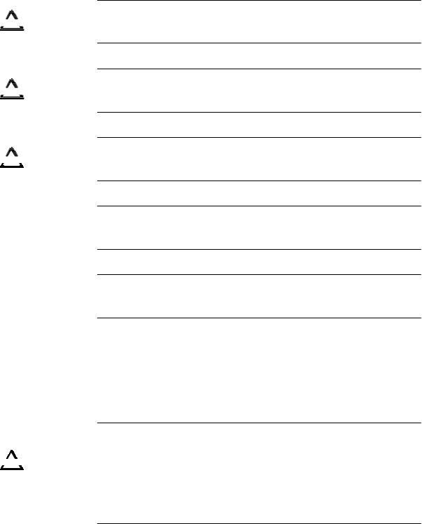
The SINUMERIK 802C base line is a compact CNC unit. It consists of the following areas (see figure 1-1):
!!!!!MLCDE
 MCPNDQ!BsfbArea
NCOD!LfztKeys
SIMODRIVETJNPESJWF!cbtf!mjofbase line
SIMODRIVETJNPESJWF!72611U/2 V0
Fig. 1-1 Components of SINUMERIK 802C base line (turning variant) |
|
SINUMERIK 802C base line |
1-1 |
Start-Up |
|

SINUMERIK 802C base line Control System
Software components
The SINUMERIK 802C base line comprises the following software components, which can be ordered:
z
z
z
System software on the permanent flash memory of the CNC
Boot software
loads the remaining system software from the permanent memory into the user memory (DRAM) and starts the system.
MMC software (Man Machine Communication), implements all operating functions
NCK software (NC Kernel)
implements all NC functions. This software controls an NC channel with a maximum of 3 movement axes and a spindle.
PLC software (Programmable Logic Control) executes the integrated PLC user program cyclically.
Integrated PLC user program
intended to adjust the SINUMERIK 802C base line to the machine functions (see also Description of Functions “Integrated User Program for SINUMERIK 802C base line”).
Toolbox
WinPCIN transfer program for a PC/PG (programming device) to transfer user data and programs
Text manager
Cycle kit for loading into the control system using WinPCIN
User program library
Technological machine data files
Programming tool
Update diskettes
Update program with operator prompting system
802C base line system software, packed, for loading and programming the SINUMERIK 802C base line via an update program.
User data |
User data are: |
z
z
z
z
z
z
z
z
Machine data
Setting data
Tool data
R parameters
Zero offsets
Compensation data
Part programs
Standard cycles
Data saving |
Modified user data are saved for at least 50 h after power off or power failure. |
||||
|
|
|
|
|
After then, they might get lost. |
|
|
|
|
|
|
|
|
|
|
|
Warning |
! |
|
|
|||
|
|
To avoid data loss, the operator must carry out data saving (see Section 4.1.4). |
|||
|
|
|
|
|
|
|
|
|
|
|
|
|
|
|
|
|
|
1-2 |
|
|
SINUMERIK 802C base line |
||
|
|
|
|
|
Start-Up |
SINUMERIK 802C base line Control System
1.2Technical data
Connected load |
Table 1–1 Connected load |
|
|
|
|
|
|
|
|
|
|
|
|
|
|
|
|
|
|
Parameter |
|
Min. |
|
Typ. |
Max. |
Unit |
|
|
Supply voltage |
|
20.4 |
|
24 |
28.8 |
V |
|
|
Ripple |
|
|
|
|
3.6 |
Vss |
|
|
Current consumption from 24 V |
|
|
|
1.5 |
|
A |
|
|
Power dissipation of CNC |
|
|
|
35 |
|
W |
|
|
Start-up current |
|
|
|
|
4 |
A |
Weight |
Table 1–2 Weight |
|
|
|
|
|
|
|
|
|
|
|
|
|
|
|
|
|
|
Component |
|
|
|
Weight [g] |
|
|
|
|
CNC |
|
|
|
4500 |
|
|
Dimensions |
Table 1–3 Component dimensions |
|
|
|
|
|
|
|
|
|
|
|
|
||||
|
|
Component |
|
Dimensions LxWxD [mm] |
||||
|
|
CNC |
|
|
|
420 x 300 x 83 |
|
|
Environmental operating conditions |
|
|
|
|
|
|
||
|
Table 1–4 Environmental operating conditions |
|
|
|
||||
|
|
|
|
|
|
|
|
|
|
|
Parameter |
|
|
|
|
|
|
|
|
Temperature range |
0...55 °C |
|
|
|
||
|
|
Permissible relative humidity |
5...95 % without condensation |
|||||
|
|
Air pressure |
700...1,060 hPa |
|
|
|||
|
The operating conditions comply with IEC 1131–2. |
|
|
|
||||
|
Installation in a housing (e.g. cubicle) is absolutely necessary for operation. |
|||||||
Transport and storage conditions |
|
|
|
|
|
|
||
|
Table 1–5 Transport and storage conditions |
|
|
|
||||
|
|
|
|
|
|
|
|
|
|
|
Parameter |
|
|
|
|
|
|
|
|
Temperature range |
Transport: –40...70 °C |
|
||||
|
|
|
Storage: -20 ... 55 °C |
|
||||
|
|
Permissible relative air humidity |
5...95 % without condensation |
|||||
|
|
Air pressure |
700...1,060 hPa |
|
|
|||
|
|
Transport height |
–1,000...3,000 m |
|
|
|||
|
|
Free fall in transport package |
|
≤1,200 mm |
|
|
||
Protective quality and degree of protection
Class of protection I to IEC 536.
No PE terminal required.
Foreign matter and water protection to IEC 529.
For CNC:IP 54 front IP 00 rear
SINUMERIK 802C base line |
1-3 |
Start-Up |
|

SINUMERIK 802C base line Control System
1-4 |
SINUMERIK 802C base line |
|
Start-Up |

Installing the Control System |
2 |
2.1Installing and Dismantling the SINUMERIK 802C base line
Warning
Do not install when the equipment is under power!
|
|
|
|
|
|
|
|
|
|
|
! |
|
|
|
The modules contain electrostatically sensitive devices. |
|
|
|
|
|
|
|
|
|
|
|
|
|
|
|
It must be ensured that persons without ESD protection never touch printed |
|
|
|
|
|
|
|
circuit boards or components when handling operator and machine control |
|
|
|
|
|
|
|
panels. |
Approach |
Due to the compactness, it is very convenient to install and dismantle the |
||||||
|
|
|
|
|
|
|
control system. |
|
|
|
|
|
|
|
1. Fix the system in the machine control station. |
|
|
|
|
|
|
|
2. Screw the system in place with 8 M4 x 16 assembled screws. The |
|
|
|
|
|
|
|
maximum allowed torque for the screws is 1.5 Nm. |
|
|
|
|
|
|
|
Notice |
|
|
|
|
|
|
|
Prior to installation, the machine control panel can be provided with an |
|
|
|
|
|
|
|
emergency stop button. If it is not required, the opening must be covered with |
|
|
|
|
|
|
|
the supplied self-adhesive cover. |
Dismantling the control system
The control system is dismantled as described above in the reverse order.
Warning
Do not dismantle when the equipment is under power!
SINUMERIK 802C base line |
2-1 |
Start-Up |
|

Installing the Control System
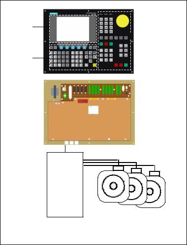
Mounting dimensions
The dimensions shown below are important for installing the control system:
802C base line
Fig. 2-1 Mounting dimensions for 802C base line
2-2 |
SINUMERIK 802C base line |
|
Start-Up |
Installing the Control System
1) |
Thread plugging M4 |
5 hole (8x) |
Fig. 2-2 Mounting dimensions for 802C base line
SINUMERIK 802C base line |
2-3 |
Start-Up |
|
Installing the Control System
2.2Interfaces and cables
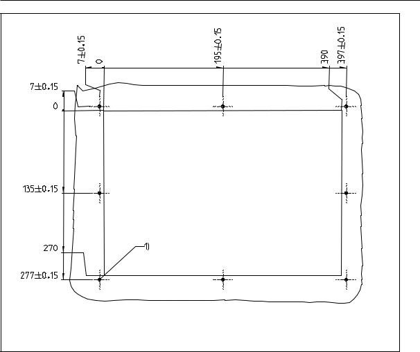
Position of the interfaces and elements
Fig. 2-3 Rear of CNC system
Interfaces |
CNC |
|
|
z |
X1 power supply terminals (DC24V) |
|
|
3-pin screw-type terminal block for connecting the 24 V load power |
|
|
supply |
|
z |
X2 RS232 interface (V24) |
|
|
9-pin sub-D plug connector |
|
z |
X3 to X5 measuring system interfaces (ENCODER) |
|
|
three 15-pin sub-D plug connectors for connecting incremental position |
|
|
encoders (RS422) |
|
z |
X6 spindle interface (ENCODER) |
|
|
15-pin sub-D socket for connecting a spindle incremental position |
|
|
encoder(RS422) |
|
z |
X7 drive interface (AXIS) |
|
|
50-pin sub-D socket connector for connecting the power sections for a |
|
|
maximum of four analog drives including spindle |
|
z |
X10 handwheel interface (MPG) |
|
|
10-pin front connector for connecting the handwheels |
2-4 |
SINUMERIK 802C base line |
|
Start-Up |

Installing the Control System
zX20 digital inputs (DI)
10-pin front connector for connecting the NC READY relay
DI/O
z
z
X100 to X105
10-pin front connector for connecting digital inputs
X200 and X201
10-pin front connector for connecting digital outputs
Operating elements |
Start-up switch S3 |
Fuse |
Fuse F1, externally designed to allow users for convenient replacement. |
S2 and D15 |
These elements are provided only for debugging internally. |
SINUMERIK 802C base line |
2-5 |
Start-Up |
|
Installing the Control System
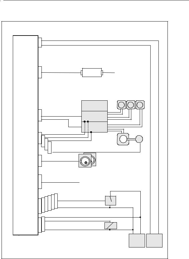
Connecting cables The components are wired up as shown in the Connection Diagram 2–4 and 2-5. For the cables required, please refer to the diagram below.
|
X1 |
P24 |
|
|
|
|
|
|
|
|
|
||
DC24V |
M |
|
|
|
|
Wire(1.0...2.0 mm2) |
|
|
|
|
|||
|
|
|
|
|
|
|
|
|
option |
|
|
|
|
|
|
6FX8002-1AA01-1..0 |
6FX2003-0DS00 |
|
|
|
|
||||||
RS232 |
X2 |
RS232 |
Communication |
|
|
||||||||
|
|
|
|
|
|
|
|
|
|||||
|
|
|
|
|
|
|
|
|
Isolator |
with Computer |
|
|
|
|
|
|
|
|
|
|
|
|
|
|
|
||
CNC |
|
|
|
|
|
|
|
|
|
|
|
|
|
|
|
|
|
|
|
|
|
|
|
1FK7 Servo Motor |
|
|
|
|
|
|
|
|
|
|
|
|
Power |
|
|
|
|
|
|
|
|
|
|
|
|
|
Module |
|
|
|
|
AXIS/ |
|
|
|
|
|
|
|
|
6SN1146-... |
|
|
|
|
X7 |
6FX2002-3AD01-1..0 |
611U |
|
|
|
|
|||||||
|
|
|
|
|
|||||||||
SPINDLE |
6SN1118-0NK |
|
|
|
|
||||||||
|
|
|
|
|
|
|
|
|
|
|
|||
|
|
|
|
|
|
|
|
|
|
|
|
||
|
|
|
|
|
|
|
|
|
|
|
|
|
|
|
|
|
|
|
|
|
|
|
611U |
Power Cable |
|
|
|
|
|
|
|
|
|
|
|
|
6SN1118-0NK |
6FX5002-5.A.1-1..0 |
|
|
|
ENCODER 1 |
|
6FX8002-2CJ10-1..0 |
|
Signal Cable |
|
|
|||||||
|
|
|
|
|
|
|
|
|
6FX5002-2CF02-1.. 0 |
|
|||
ENCODER 2 |
X3 |
X4 |
|
|
|
|
|
|
|
|
|
|
|
ENCODER 3 |
X5 |
|
|
|
|
|
|
|
|
|
|
||
SPINDLE |
X6 |
|
Spindle |
6FX5002-2CD01-1BB0 |
1PH Spindle |
Spindle External |
|
|
|||||
ENCODER |
|
Motor |
Encoder |
|
|||||||||
|
|
|
|
|
|
||||||||
|
|
|
|
|
|
|
|
|
|
||||
MPG |
X10 |
6FX8002-2BB01-1..0 |
Hand Wheels 1...2 |
|
|||||||||
|
|
|
|
|
|
|
|
|
|||||
|
|
|
|
|
|
|
|
|
|
|
|||
DI |
X20 |
|
|
|
|
|
|
|
NC READY |
|
|
|
|
IN |
|
|
|
|
|
|
|
|
|
|
|
|
|
0.0...0.7 |
|
|
|
X103 |
X104 |
X105 |
IN |
|
|
|
|
|
|
1.0...1.7 |
|
|
X102 |
|
|
signal |
|
|
|
||||
X100 |
X101 |
|
|
|
|
|
|
||||||
2.0...2.7 |
Wire(0.14...1.5 mm2) |
1...48 |
|
|
|
||||||||
3.0...3.7 |
|
|
|
||||||||||
|
|
|
|
|
|
|
|||||||
4.0...4.7 |
M |
|
|
|
|
|
|
||||||
|
|
|
|
|
|
|
|
|
|
|
|
||
5.0...5.7 |
|
|
|
|
|
|
|
|
|
|
|
|
|
|
|
|
P24 |
|
|
|
|
|
|
|
|||
|
|
|
|
|
|
|
|
|
|
|
|||
OUT |
X200 |
X201 |
|
OUT |
|
|
|
|
|
|
|
||
0.0...0.7 |
|
|
|
|
|
|
2 |
load |
|
|
|
||
1.0...1.7 |
|
|
|
|
|
|
|
|
|
|
|||
|
|
M |
|
Wire(0.14...1.5 mm ) |
1...16 |
|
|
|
|||||
|
|
|
|
|
|
|
|||||||
|
|
|
|
|
|
|
|
|
|
M |
P24 |
M |
P24 |
|
|
|
|
|
|
|
|
|
|
24VDC |
24VDC |
||
Fig. 2-4 Connection Diagram for SINUMERIK 802C base line with SIMODRIVE 611U
2-6 |
SINUMERIK 802C base line |
|
Start-Up |

Installing the Control System
DC24V |
X1 |
P24 |
|
|
|
|
|
|
|
|
|
||
|
|
|
|
|
|
2 |
|
|
|
|
|
||
|
M |
|
|
|
Wire(1.0...2.0 mm ) |
|
|
|
|
|
|||
|
|
|
|
|
|
|
|
|
|
||||
|
|
|
|
|
|
|
|
option |
|
|
|
|
|
|
|
|
|
|
|
|
|
6FX2003-0DS00 |
|
|
|
|
|
RS232 |
X2 |
6FX8002-1AA01-1..0 |
RS232 |
Communication |
|
|
|
||||||
|
|
|
|
|
|
|
|
Isolator |
with Computer |
|
|
|
|
CNC |
|
|
|
|
|
|
|
|
|
|
|
|
|
|
|
|
|
|
|
|
|
|
1FK7 Servo Motor |
|
|
|
|
|
|
|
|
|
|
|
|
SIMODRIVE |
|
|
|
|
|
|
|
|
|
|
|
|
|
base line |
|
|
|
|
|
AXIS/ |
X7 |
6FX2002-3AD01-1..0 |
6FC5548-0AC..-0AA0 |
|
|
|
|
|
|||||
SPINDLE |
|
|
|
|
|
|
|
|
|
|
|
||
|
|
|
|
|
|
|
|
|
|
|
|
|
|
|
|
|
|
|
|
|
|
|
Power Cable |
|
|
|
|
|
|
|
|
|
|
|
|
|
6FX5002-5DA01-1..0 |
|
|
|
|
ENCODER 1 |
|
6FX5002-2CJ00-1..0 |
Spindle Controller |
Position Feeback |
|
|
|||||||
|
Cable |
|
|
|
|
||||||||
|
|
|
|
|
|
||||||||
ENCODER 2 |
X3 |
|
|
|
|
|
|
|
6FX5002-2CF02-1..0 |
|
|||
ENCODER 3 |
X4 |
X5 |
|
|
|
|
|
|
|
|
|
|
|
SPINDLE |
X6 |
|
|
|
|
1PH Spindle |
|
|
|
|
|||
ENCODER |
|
|
|
|
|
|
|
|
Motor |
Spindle |
External |
Encodre |
|
MPG |
X10 |
6FX8002-2BB01-1..0 |
Hand Wheels 1…2 |
|
|||||||||
|
|
|
|
|
|
|
|
||||||
|
|
|
|
|
|
|
|
|
|
||||
DI |
X20 |
|
|
|
|
|
|
NC READY |
|
|
|
|
|
|
|
|
|
|
|
|
|
|
|
|
|
||
IN |
|
|
|
|
|
|
|
|
|
|
|
|
|
0.0...0.7 |
|
|
|
X103 |
X104 |
X105 |
IN |
|
Signal |
|
|
|
|
1.0...1.7 |
X100 |
X101 |
X102 |
|
|
|
|
|
|||||
2.0...2.7 |
Wire(0.14...1.5 mm2) |
1...48 |
|
|
|
|
|||||||
3.0...3.7 |
|
|
|
|
|||||||||
4.0...4.7 |
M |
|
|
|
|
|
|
||||||
|
|
|
|
|
|
|
|
|
|
|
|
||
5.0...5.7 |
|
|
|
P24 |
|
|
|
|
|
|
|
||
|
|
|
|
|
|
|
|
|
|
|
|||
|
|
|
|
|
|
|
|
|
|
|
|
||
OUT |
X200 |
X201 |
|
OUT |
|
|
Load |
|
|
|
|
||
0.0...0.7 |
|
|
|
|
|
|
|
|
|
|
|||
|
M |
|
|
Wire(0.14...1.5 mm2) |
1...16 |
|
|
|
|
||||
1.0...1.7 |
|
|
|
|
|
|
|
||||||
|
|
|
|
|
|
|
|
|
M |
P24 |
M |
P24 |
|
|
|
|
|
|
|
|
|
|
24VDC |
|
24VDC |
||
Fig. 2-5 Connection Diagram for SINUMERIK 802C base line with SIMODRIVE base line
SINUMERIK 802C base line |
2-7 |
Start-Up |
|

Installing the Control System
2.3Connecting the individual components
Connecting the components
Please note the following:
Notice
Use only shielded cable and make sure that the shield is connected to the metal or metal plated connector casing on the control side. For the purpose of isolating the analog setpoint signal from low-frequency interference, we recommend not to ground the shield on the drive side.
The preassembled cable offered as accessories provides optimum protection against interference.
General procedure:
Proceed as follows to connect the individual components:
1.Connect the cables to the components as shown in Fig. 2–4 or Fig. 2-5.
2.Fix the sub-D connector in place using the knurled screws.
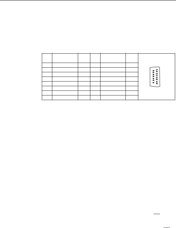
2.3.1Connecting the feed drives and the spindle (X7)
Pin assignments For connector on the CNC side
Feed drive interface |
|
|
|
|
|
|
|
|||
Connector designation: X7 |
|
|
|
|
|
|||||
|
|
|
|
AXIS 1–4 |
|
|
|
|
|
|
Connector type: |
|
50-pin sub-D plug connector |
|
|
|
|||||
Table 2-1 Pin assignments of connector X7 |
|
|
|
|
||||||
|
|
|
|
|
|
|
|
|
|
|
|
|
|
|
|
|
X7 |
|
|
|
|
|
Pin |
Signal |
Type |
|
Pin |
Signal |
Type |
Pin |
Signal |
Type |
|
1 |
AO1 |
AO |
|
18 |
n.c. |
|
34 |
AGND1 |
AO |
|
2 |
AGND2 |
AO |
|
19 |
n.c. |
|
35 |
AO2 |
AO |
|
3 |
AO3 |
AO |
|
20 |
n.c. |
|
36 |
AGND3 |
AO |
|
4 |
AGND4 |
AO |
|
21 |
n.c. |
|
37 |
AO4 |
AO |
|
5 |
n.c. |
|
|
22 |
M |
VO |
38 |
n.c. |
|
|
6 |
n.c. |
|
|
23 |
M |
VO |
39 |
n.c. |
|
|
7 |
n.c. |
|
|
24 |
M |
VO |
40 |
n.c. |
|
|
8 |
n.c. |
|
|
25 |
M |
VO |
41 |
n.c. |
|
|
9 |
n.c. |
|
|
26 |
n.c. |
|
42 |
n.c. |
|
|
10 |
n.c. |
|
|
27 |
n.c. |
|
43 |
n.c. |
|
|
11 |
n.c. |
|
|
28 |
n.c. |
|
44 |
n.c. |
|
|
12 |
n.c. |
|
|
29 |
n.c. |
|
45 |
n.c. |
|
|
13 |
n.c. |
|
|
30 |
n.c. |
|
46 |
n.c. |
|
|
14 |
SE1.1 |
K |
|
31 |
n.c. |
|
47 |
SE1.2 |
K |
|
15 |
SE2.1 |
K |
|
32 |
n.c. |
|
48 |
SE2.2 |
K |
|
16 |
SE3.1 |
K |
|
33 |
n.c. |
|
49 |
SE3.2 |
K |
|
17 |
SE4.1 |
K |
|
|
|
|
50 |
SE4.2 |
K |
2-8 |
SINUMERIK 802C base line |
|
Start-Up |
Installing the Control System
Signal names |
Description |
AOn |
Analog Command Value |
AGNDn |
Analog Ground |
SEn.1; SEn.2 |
Servo Enable Relay |
M |
Ground (not to be connected) |
n = 1...4 |
Number of Axis |
Signal Specification: |
+/-10V for Analog Outputs |
Signal level |
RS422 |
Signal type |
|
VO |
Signal output |
K |
Switching contact |
Axis assignment |
|
1 |
X axis |
2 |
Y axis |
3 |
Z axis |
4 |
Spindle |
Table 2–2 Cable assignment (for type 6FX2 002-3AD01)
|
|
CNC Side |
Cable |
Drive Side |
||
|
|
|
PIN |
Core Color |
Signal Name |
PIN |
|
|
|
14 |
black |
1st axis |
1.9 |
|
|
|
47 |
brown |
|
1.65 |
|
|
|
34 |
red |
|
1.14 |
34 |
|
1 |
1 |
orange |
|
1.56 |
18 |
15 |
yellow |
2nd axis |
2.9 |
||
|
|
|
||||
|
|
|
48 |
green |
|
2.65 |
|
|
|
2 |
blue |
|
2.14 |
|
|
|
35 |
purple |
|
2.56 |
|
|
|
16 |
gray |
3rd axis |
3.9 |
|
|
|
49 |
pink |
|
3.65 |
|
|
|
36 |
white/black |
|
3.14 |
|
|
|
3 |
white/brown |
|
3.56 |
50 |
33 |
17 |
17 |
white/red |
Spindle |
4.9 |
|
|
|
||||
|
|
|
50 |
white/orange |
|
4.65 |
|
|
|
4 |
white/yellow |
|
4.14 |
|
|
|
37 |
white/green |
|
4.56 |
SINUMERIK 802C base line |
2-9 |
Start-Up |
|

Installing the Control System
Drives with analog interface
Signals:
A voltage and an enable signal are output.
zAOn (SETPOINT)
Analog voltage signal in the range ± 10 V to output a speed setpoint
zAGNDn (REFERENCE SIGNAL)
Reference potential (analog ground) for the setpoint signal, internally connected to logic ground.
zSEn (SERVO ENABLE)
Relay contact pair controlling the enable of the power section, e.g. of a SIMODRIVE drive unit controlled via a PLC program.
Signal parameters
The setpoint is output as an analog differential signal.
Table 2–3 Electrical parameters of the signal outputs for step-switching drives
|
Parameter |
Min |
|
Max |
|
Unit |
|
Voltage range |
–10.5 |
|
10.5 |
|
V |
|
Output current |
–3 |
|
3 |
|
mA |
Relay contact |
|
|
|
|
|
|
Table 2–4 Electrical parameters of the relay contacts |
|
|
||||
|
|
|
|
|
|
|
|
Parameter |
|
|
Max. |
|
Unit |
|
Switching voltage |
|
50 |
|
V |
|
|
Switching current |
|
1 |
|
A |
|
|
Switching power |
|
30 |
|
VA |
|
Cable length: max. 35 m
2-10 |
SINUMERIK 802C base line |
|
Start-Up |
Installing the Control System
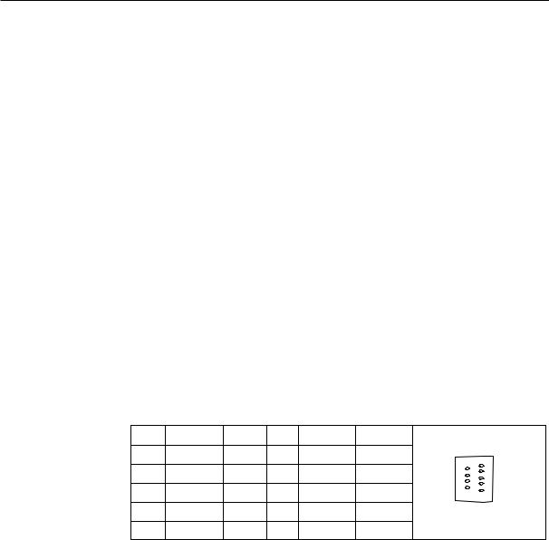
2.3.2Connecting the measuring systems (X3 ... X6)
Pin assignment of the connector on the CNC side
Measuring system interface (incremental encoder)
Connector designation: X3 ... X6
ENCODER
Connector type: 15-pin sub-D plug connector
Table 2–5 Pin assignment of the female connector X3 ... X6
Pin |
Signal |
Type |
Pin |
Signal |
Type |
|
|
1 |
n.c. |
|
9 |
M |
VO |
|
|
2 |
n.c. |
|
10 |
Z |
I |
15 |
8 |
3 |
n.c. |
|
11 |
Z_N |
I |
|
|
4 |
P5_MS |
VO |
12 |
B_N |
I |
|
|
5 |
n.c. |
|
13 |
B |
I |
9 |
1 |
6 |
P5_MS |
VO |
14 |
A_N |
I |
|
|
7 |
M |
VO |
15 |
A |
I |
|
|
8 |
n.c. |
|
|
|
|
|
|
Signal names |
Description |
|
|
|
|||
A; A_N |
Track A |
|
|
|
|
||
B; B_N |
Track B |
|
|
|
|
||
Z; Z_N |
|
Zero Reference Mark |
|
|
|
||
P5_MS |
+5,2V Supply Voltage |
|
|
|
|||
M |
|
Ground |
|
|
|
|
|
Signal Specification: RS422 |
|
|
|
|
|||
Signal type |
|
|
|
|
|
|
|
VO |
|
Voltage output (supply) |
|
|
|
||
I |
|
5V input (5V signal) |
|
|
|
||
Connectable encoder types
Incremental 5 V encoders can be connected directly.
Characteristics The encoders must meet the following requirements:
Transmission method: Differential transmission with 5 V square-wave signals
Output signals: |
Track A as true and negated signal (Ua1, |
U a1 ) |
||
|
|
|
|
|
|
Track B as true and negated signal (Ua2, |
U a 2 ) |
||
|
Zero signal N as true and negated signal (Ua0, |
|||
Max. output frequency: 1.5 MHz
Phase offset between
tracks A and B: 90º ± 30º Current onsumption: max. 300 mA
SINUMERIK 802C base line
Start-Up
U a 0 )
2-11
Installing the Control System
Cable lengths The maximum cable length depends on the specifications of the encoder power supply and on the transmission frequency.
To provide fault-free operation, make sure that the following values are not exceeded when using preassembled interconnecting cables from SIEMENS:
Table 2–6 Maximum cable lengths depending on the encoder power supply
Supply Voltage |
Tolerance |
Current Consumption |
Max. Cable |
|
Length |
||||
|
|
|
||
5 V DC |
4.75 V...5.25 V |
< 300 mA |
25 m |
|
5 V DC |
4.75 V...5.25 V |
< 220 mA |
35 m |
Table 2–7 Maximum cable lengths depending on the transmission frequency
Encoder Type |
Frequency |
Max. Cable Length |
incremental |
1 MHz |
10 m |
|
500 kHz |
35 m |
2.3.3Configuration of the RS232 interface connection (X2)
Pin assignment of connector on the CNC side
RS232 interface |
|
|
|
|
|
|
|
Connector designation: X2 |
|
|
|
|
|||
|
|
RS232 |
|
|
|
|
|
Connector type: |
9-pin sub-D plug connector |
|
|
||||
Table 2–8 Pin assignment of connector X2 |
|
|
|
||||
Pin |
Name |
Type |
Pin |
Name |
Type |
|
|
1 |
|
|
6 |
DSR |
I |
|
|
2 |
RxD |
I |
7 |
RTS |
O |
6 |
1 |
3 |
TxD |
O |
8 |
CTS |
I |
9 |
5 |
|
|
|
|
|
|
|
|
4 |
DTR |
O |
9 |
|
|
|
|
5 |
M |
VO |
|
|
|
|
|
Signal description: |
|
|
|
|
|
||
RxD |
|
Receive Data |
|
|
|
||
TxD |
|
Transmit Data |
|
|
|
||
RTS |
|
Request to send |
|
|
|
||
CTS |
|
Clear to send |
|
|
|
||
DTR |
|
Data Terminal Ready |
|
|
|||
DSR |
|
Data Set Ready |
|
|
|
||
M |
|
Ground |
|
|
|
|
|
Signal level
RS232
2-12 |
SINUMERIK 802C base line |
|
Start-Up |
Installing the Control System
Signal type |
|
I |
Input |
O |
Output |
VO |
Voltage output |
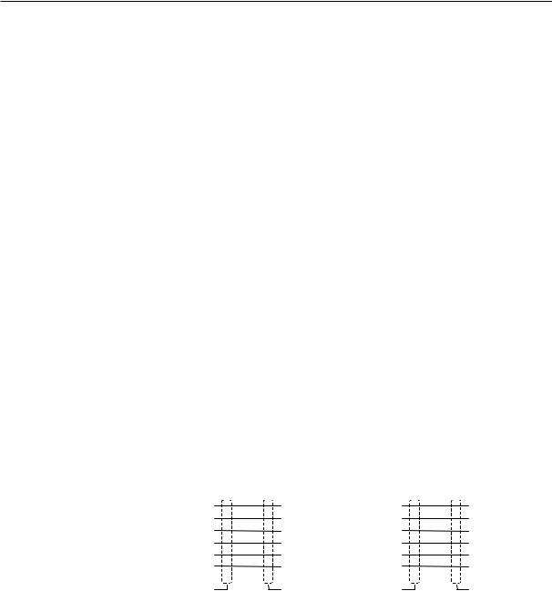
Cable for WinPCIN Table 2–9 Cable for WinPCIN: Pin assignment of the Sub-D connector
|
|
9-Pin |
|
|
|
|
Name |
|
|
|
|
|
25-Pin |
||||
|
1 |
|
Shield |
|
|
|
|
|
|
|
|
|
1 |
|
|
||
|
2 |
|
RxD |
|
|
|
|
|
|
|
|
|
2 |
|
|
||
|
3 |
|
TxD |
|
|
|
|
|
|
|
|
|
3 |
|
|
||
|
4 |
|
DTR |
|
|
|
|
|
|
|
|
|
6 |
|
|
||
|
5 |
|
M |
|
|
|
|
|
|
|
|
|
7 |
|
|
||
|
6 |
|
DSR |
|
|
|
|
|
|
|
|
|
20 |
|
|
||
|
7 |
|
RTS |
|
|
|
|
|
|
|
|
|
5 |
|
|
||
|
8 |
|
CTS |
|
|
|
|
|
|
|
|
|
4 |
|
|
||
|
9 |
|
|
|
|
|
|
|
|
|
|
|
|
|
|
|
|
Or |
|
|
|
|
|
|
|
|
|
|
|
|
|
|
|||
|
|
|
|
|
|
|
|
|
|
|
|
|
|
|
|
|
|
|
|
9-Pin |
|
|
|
|
Name |
|
|
|
|
|
9-Pin |
||||
|
1 |
|
Shield |
|
|
|
|
|
|
|
|
|
1 |
|
|
||
|
2 |
|
RxD |
|
|
|
|
|
|
|
|
|
3 |
|
|
||
|
3 |
|
TxD |
|
|
|
|
|
|
|
|
|
2 |
|
|
||
|
4 |
|
DTR |
|
|
|
|
|
|
|
|
|
6 |
|
|
||
|
5 |
|
M |
|
|
|
|
|
|
|
|
|
5 |
|
|
||
|
6 |
|
DSR |
|
|
|
|
|
|
|
|
|
4 |
|
|
||
|
7 |
|
RTS |
|
|
|
|
|
|
|
|
|
8 |
|
|
||
|
8 |
|
CTS |
|
|
|
|
|
|
|
|
|
7 |
|
|
||
|
9 |
|
|
|
|
|
|
|
|
|
|
|
|
|
|
|
|
|
|
|
|
|
|
|
|
|
|
|
|
|
|
|
|
||
|
|
6 & EDVH OLQH |
3& |
|
|
6 & EDVH OLQH |
3& |
|
|
|
|||||||
|
|
SLQ 6XE ' |
SLQ 6XE ' |
SLQ 6XE ' |
SLQ 6XE ' |
|
|||||||||||
|
|
|
|
|
0 .1 m m 2 |
|
|
|
|
|
|
0 .1 m m 2 |
|
|
|
|
|
|
|
|
R x D |
2 |
|
3 |
T xD |
|
R xD |
2 |
|
2 R xD |
|
|
|||
|
|
|
|
|
|
|
|
|
|
||||||||
|
|
|
T x D |
3 |
|
|
2 |
R xD |
|
T xD |
3 |
|
|
3 T xD |
|
|
|
|
|
|
D T R |
4 |
|
|
6 |
D S R |
|
D T R |
4 |
|
|
6 D S R |
|
|
|
|
|
|
0 V |
5 |
|
|
5 |
0 V |
|
0 V |
5 |
|
|
7 0 V |
|
|
|
|
|
|
D S R |
6 |
|
|
4 |
D T R |
|
D S R |
6 |
|
|
2 0 D T R |
|
|
|
|
|
|
R T S |
7 |
|
|
8 |
C T S |
|
R T S |
7 |
|
|
5 C T S |
|
|
|
|
|
|
C T S |
8 |
|
|
7 |
R T S |
|
C T S |
8 |
|
|
4 R T S |
|
|
|
|
|
|
|
|
|
|
|
|
|||||||||
|
|
|
|
|
|
|
|
|
|
|
|
|
|
|
|
|
|
|
|
|
|
|
|
|
|
|
|
|
|
|
|
|
|
|
|
Fig. 2-5 Communication connector RS232(X2)
SINUMERIK 802C base line |
2-13 |
Start-Up |
|

Installing the Control System
2.3.4Connecting handwheels (X10)
Pin assignment of connector on the CNC side
Handwheel interface |
|
|
|
|
|
||
Connector designation: X10 |
|
|
|
|
|||
|
|
|
MPG |
|
|
|
|
Connector type: |
10-pin mini–Combicon plug connector |
|
|||||
Table 2–10 Pin assignment of connector X10 |
|
||||||
|
|
|
|
|
|
|
|
|
|
|
|
X10 |
|
||
|
Pin |
Name |
Type |
|
|
||
|
1 |
A1 |
|
I |
|
|
1 |
|
2 |
A1_N |
|
I |
|
|
|
|
3 |
B1 |
|
I |
|
|
|
|
4 |
B1_N |
|
I |
|
|
|
|
5 |
P5_MS |
|
VO |
|
|
|
|
6 |
M5_MS |
|
VO |
|
|
|
|
7 |
A2 |
|
I |
|
|
|
|
8 |
A2_N |
|
I |
|
|
10 |
|
9 |
B2 |
|
I |
|
|
|
|
|
|
|
|
|
|
|
|
10 |
B2_N |
|
I |
|
|
|
Signal names
A1, A1_N
B1, B1_N
A2, A2_N
B2, B2_N
P5_MS
M
Signal level
RS422
Signal type
VO
I
Track A, true and negated (handwheel 1) Track B, true and negated (handwheel 1) Track A, true and negated (handwheel 2) Track B, true and negated (handwheel 2) 5.2 V supply voltage for handwheels Supply ground
Voltage output
Input (5 V signal)
Handwheels |
Two electronic handwheels can be connected which must meet the following |
|
requirements: |
Transmission method: 5 V square-wave (TTL level or RS422) |
|
|
|
|
|
|
|
|
|
Signals: |
Track A as true and negated signal (Ua1, |
U a1 |
||
|
|
|
|
|
|
Track B as true and negated signal (Ua2, |
U a 2 |
||
Max. output frequency: 500 kHz |
|
|
|
|
)
)
Phase offset between |
90º ± 30º |
tracks A and B: |
|
Supply: |
5 V, max. 250 Ma |
2-14 |
SINUMERIK 802C base line |
|
Start-Up |
Installing the Control System
2.3.5Connecting NCREADY (X20)
Pin assignment of connector on the CNC side
NCREADY interface
Connector designation: X20
DI
Connector type: 10-pin plug connector
Table 2–11 Pin assignment of connector X20
|
|
X20 |
Pin |
Signal |
Type |
1 |
NCRDY_1 |
K |
2 |
NCRDY_2 |
K |
3 |
I0 / BERO1 |
Not defined |
4 |
I1 / BERO2 |
Not defined |
5 |
I2 / BERO3 |
Not defined |
6 |
I3 / BERO4 |
Not defined |
7 |
I4 / MEPU1 |
Not defined |
8 |
I5 / MEPU2 |
Not defined |
9 |
L- |
VI |
10 |
L- |
VI |
11
20
Signal description: |
|
NCRDY_1…2 |
NC-READY-Contact, max. current is 2A at 150VDC or |
|
125VAC) |
I0 ... I6 |
Fast digital input 0 … 6 |
L- |
Reference potential for digital input |
Signal type |
|
K |
Switching contact |
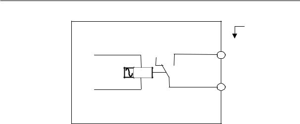
NC–READY output Readiness in the form of a relay contact (NO); can be integrated into the EMERGENCY STOP circuit.
Table 2–12 Electrical parameters of the NCREADYrelay contact
Parameter |
Max. |
Unit |
DC switching voltage |
50 |
V |
Switching current |
1 |
A |
Switching power |
30 |
VA |
SINUMERIK 802C base line |
2-15 |
Start-Up |
|
Installing the Control System
|
|
Pin num ber of |
|
Relay |
X20 |
|
|
|
NC _RDY |
|
1 |
|
|
|
1P5 |
|
2 |
|
|
|
Fig. 2-5 |
|
|
The NCREADY is an internal relay of NC. 1 and 2 are the two contacts of this relay. It will open when NC is not ready, and close after NC is ready for operation.
2-16 |
SINUMERIK 802C base line |
|
Start-Up |

Installing the Control System
2.3.6Connecting the digital inputs (X100 ... X105)
Pin assignment for connector
Interface for the digital inputs |
|
|||
Connector designation: |
X100, X101, X102, X103, X104, X105 |
|||
|
|
IN |
|
|
Connector type: |
10-pin plug connector |
|||
Table 2–13 Connector pin assignment |
|
|||
|
|
X100 |
|
|
Pin |
Name |
Type |
|
|
1 |
n.c. |
|
X100 |
|
2 |
DI0 |
DI |
||
|
||||
3 |
DI1 |
DI |
0 |
|
4 |
DI2 |
DI |
1 |
|
2 |
||||
5 |
DI3 |
DI |
||
3 |
||||
6 |
DI4 |
DI |
4 |
|
5 |
||||
7 |
DI5 |
DI |
||
6 |
||||
8 |
DI6 |
DI |
7 |
|
9 |
DI7 |
DI |
M |
|
|
||||
10 |
M |
VI |
|
|
|
|
X101 |
|
|
Pin |
Name |
Type |
|
|
1 |
n.c. |
|
X101 |
|
2 |
DI8 |
DI |
||
|
||||
3 |
DI9 |
DI |
8 |
|
4 |
DI10 |
DI |
9 |
|
10 |
||||
5 |
DI11 |
DI |
||
11 |
||||
6 |
DI12 |
DI |
12 |
|
13 |
||||
7 |
DI13 |
DI |
||
14 |
||||
8 |
DI14 |
DI |
15 |
|
9 |
DI15 |
DI |
M |
|
|
||||
10 |
M |
VI |
|
|
|
|
X102 |
|
|
Pin |
Name |
Type |
1 |
n.c. |
|
2 |
DI16 |
DI |
3 |
DI17 |
DI |
4 |
DI18 |
DI |
5 |
DI19 |
DI |
6 |
DI20 |
DI |
7 |
DI21 |
DI |
8 |
DI22 |
DI |
9 |
DI23 |
DI |
10 |
M |
VI |
X102
16
17
18
19
20
21
22
23 M
SINUMERIK 802C base line |
2-17 |
Start-Up |
|

Installing the Control System
|
|
|
X103 |
|
Pin |
Name |
Type |
|
|
1 |
n.c. |
|
X103 |
|
2 |
DI24 |
DI |
24 |
|
3 |
DI25 |
DI |
||
25 |
||||
4 |
DI26 |
DI |
26 |
|
5 |
DI27 |
DI |
27 |
|
28 |
||||
6 |
DI28 |
DI |
||
29 |
||||
7 |
DI29 |
DI |
30 |
|
8 |
DI30 |
DI |
31 |
|
M |
||||
9 |
DI31 |
DI |
|
|
10 |
M |
VI |
|
|
|
|
|
X104 |
|
Pin |
Name |
Type |
|
|
1 |
n.c. |
|
X104 |
|
2 |
DI32 |
DI |
||
|
||||
3 |
DI33 |
DI |
32 |
|
4 |
DI34 |
DI |
33 |
|
34 |
||||
5 |
DI35 |
DI |
||
35 |
||||
6 |
DI36 |
DI |
36 |
|
37 |
||||
7 |
DI37 |
DI |
||
38 |
||||
8 |
DI38 |
DI |
39 |
|
9 |
DI39 |
DI |
M |
|
|
||||
10 |
M |
VI |
|
|
|
|
|
X105 |
|
Pin |
Name |
Type |
|
|
1 |
n.c. |
|
X105 |
|
2 |
DI40 |
DI |
||
|
||||
3 |
DI41 |
DI |
40 |
|
4 |
DI42 |
DI |
41 |
|
42 |
||||
5 |
DI43 |
DI |
||
43 |
||||
6 |
DI44 |
DI |
44 |
|
45 |
||||
7 |
DI45 |
DI |
||
46 |
||||
8 |
DI46 |
DI |
47 |
|
9 |
DI47 |
DI |
M |
|
|
||||
10 |
M |
VI |
|
|
Signal names |
|
|
||
DI0...47 |
24 V digital inputs |
|||
Signal type |
|
|
|
|
VI |
Voltage input |
|
||
DI |
Input (24 V signal) |
|||
Table 2–14 Electrical parameters of the digital inputs
Parameter |
Value |
Unit |
Note |
“1” signal, voltage range |
15...30 |
V |
|
“1” signal, current consumption |
2...15 |
mA |
|
“0” signal, voltage range |
–3...5 |
V |
or input open |
Signal delay 0 Æ 1 |
0.5...3 |
ms |
|
Signal delay 1 Æ 0 |
0.5...3 |
ms |
|
2-18 |
SINUMERIK 802C base line |
|
Start-Up |
 Loading...