


 Loading...
AXIOM Iconos R200 with fixed table height
Operator Manual
AXIOM Iconos R200 with fixed table height
Operator Manual
Rückenschild für Ordner A4 (50 mm Rückenbreite); Zuschneiden auf 205 mm x 50 mm
AXIOM Iconos R200 with fixed table height
Operator Manual
AXIOM Iconos R200 with fixed table height
Operator Manual
Rückenschild für Ordner A4 (30 mm Rückenbreite); Zuschneiden auf 205 mm x 23 mm
AXD3-340.620.13.01.02 AXD3-340.620.13.01.02 AXD3-340.620.13.01.02 AXD3-340.620.13.01.02
Drucknummer zum Aufkleben

Safety |
1 |
System Overview |
2 |
System Operation |
3 |
AXIOM |
|
Examination |
4 |
Generator |
5 |
Digital Image Processing |
6 |
Interventional Application |
7 |
|
8 |
Operating Manual
AXIOM Iconos R200 with fixed table height
©Siemens AG 2002 All rights reserved
Order No.: AXD3-340.620.13.01.02
Printed in the Federal Republic of Germany
AG 12.2007
|
Contact Information: |
Siemens AG |
Siemens AG, Medical Solutions AX |
Wittelsbacherplatz 2 |
Siemensstrasse 1 |
DE-80333 Muenchen |
D-91301 Forchheim |
Germany |
Germany |
|
Phone: +49 9191 18-0 |
|
Internet: www.medical.siemens.com |
Stands/Tube Supports |
9 |
Bucky Wall Unit |
10 |
System Configuration/Options |
11 |
Accessories |
12 |
Exposure Table |
13 |
Addendum/Current Information |
14 |
Technical Description |
15 |

Important information from the manufacturer
This product is provided with a CE marking in accordance with the regulations stated in Appendix II of the Directive 93/42/EEC of June 14th, 1993 concerning medical devices.
In accordance with Appendix IX of the Directive 93/42/EEC, this device is assigned to class II b.
The CE marking applies only to medical devices which have been put on the market according to the above-mentioned EC Directive.
Unauthorized changes to this product invalidate this declaration.
Please observe the Safety Operator Manual.
Important information is given there.
The original version of this manual was written in English.

AXIOM Iconos R200
Overall Table of Contents
OperatorLists Manual
Overall Table of Contents
Part: Lists |
|
|
Chapter: Overall Table of Contents |
....................................................................................................... |
1 |
Part: System Overview |
|
|
Chapter: System Description.................................................................................................................. |
|
5 |
Application ............................................................................................................................................ |
|
5 |
Product description ............................................................................................................................... |
|
5 |
System configuration ............................................................................................................................ |
|
6 |
System overview .................................................................................................................................. |
|
7 |
Unit overview ........................................................................................................................................ |
|
8 |
Chapter: Protective Measures.............................................................................................................. |
|
11 |
Emergency Procedures ....................................................................................................................... |
|
11 |
Cleaning and disinfection .................................................................................................................... |
|
11 |
Radiation protection zones .................................................................................................................. |
|
12 |
Mechanical safety ............................................................................................................................... |
|
15 |
Safety-relevant parts subject to wear ................................................................................................. |
22 |
|
Maintenance intervals ......................................................................................................................... |
|
22 |
CAREWATCH ...................................................................................................................................... |
|
22 |
Chapter: Operating and Display Elements........................................................................................ |
25 |
|
System remote control console .......................................................................................................... |
|
25 |
Generator on/off console .................................................................................................................... |
|
32 |
Foot switch for fluoroscopy and radiography ......................................................in the control room |
33 |
|
Tableside control panel ....................................................................................................................... |
|
33 |
LCD Monitor ....................................................................................................................................... |
|
35 |
Primary collimator ............................................................................................................................... |
|
36 |
Part: System Operation |
|
|
Chapter: On-Off/Emergency Stop ......................................................................................................... |
|
5 |
Switching the system on ...................................................................................................................... |
|
5 |
Switching the system off ...................................................................................................................... |
|
6 |
Emergency SHUTDOWN button (installed ..............................................................................on-site) |
6 |
|
Standby power supply .......................................................................................................................... |
|
6 |
Red Emergency STOP button ............................................................................................................... |
|
7 |
Patient rescue ....................................................................................................................................... |
|
8 |
AXIOM Iconos R200 |
AXD3 - 340.620.13.01.02 |
1 / 4 |

AXIOM Iconos R200 |
|
Overall Table of Contents |
|
Chapter: Functional and Safety Check ................................................................................................. |
9 |
Daily tests ............................................................................................................................................. |
9 |
Monthly tests ...................................................................................................................................... |
10 |
Legally required tests .......................................................................................................................... |
10 |
Chapter: System Settings...................................................................................................................... |
11 |
General notes ...................................................................................................................................... |
11 |
Moving the X-ray system longitudinally .............................................................................................. |
14 |
Tabletop .............................................................................................................................................. |
15 |
Tube assembly stand .......................................................................................................................... |
17 |
Tabletop .............................................................................................................................................. |
18 |
Compression device (optional) ............................................................................................................ |
21 |
Tomographic equipment (optional) ..................................................................................................... |
22 |
Manual tube assembly rotation ........................................................................................................... |
24 |
Moving the grid into / out of the beam path ....................................................................................... |
24 |
Setting the source-image distance ..................................................................................................... |
25 |
Chapter: Setting the Image Geometry ............................................................................................... |
27 |
Limiting the radiation field (collimation) .............................................................................................. |
27 |
CAREPOSITION (optional) .................................................................................................................. |
29 |
Additional Cu filter ............................................................................................................................... |
30 |
Image reversal .................................................................................................................................... |
30 |
Switching over the image intensifier format ....................................................................................... |
31 |
Part: Examination |
|
Chapter: Transferring and Positioning the Patient ............................................................................ |
5 |
General information .............................................................................................................................. |
5 |
Positioning the patient .......................................................................................................................... |
5 |
Chapter: Fluoroscopy ................................................................................................................................ |
7 |
Fluoroscopy operating modes .............................................................................................................. |
7 |
Selecting the fluoroscopy operating mode ........................................................................................... |
7 |
Changing the selection of the fluoroscopy operating mode ................................................................. |
7 |
Releasing fluoroscopy ........................................................................................................................... |
9 |
Fluoroscopic data .................................................................................................................................. |
9 |
Automatic fluoroscopic control ........................................................................................................... |
10 |
Fluoroscopy time limit ......................................................................................................................... |
11 |
Fluoroscopy warning signal ................................................................................................................. |
11 |
Automatic format collimation in fluoroscopy ...................................................................................... |
11 |
Fluoroscopy programs ........................................................................................................................ |
11 |
Dose reduction .................................................................................................................................... |
12 |
Chapter: Cassette Exposures in the Spotfilm Device (optional)................................................. |
13 |
Automatic format collimation in radiography ...................................................................................... |
13 |
Cassette program ............................................................................................................................... |
14 |
Loading / unloading the spotfilm device ............................................................................................. |
16 |
2 / 4 |
AXD3-340.620.13.01.02 |
Operator Manual |

|
AXIOM Iconos R200 |
|
Overall Table of Contents |
Exposure measurement for cassette exposures ................................................................................ |
17 |
Releasing the exposure ...................................................................................................................... |
19 |
Organ programs .................................................................................................................................. |
19 |
Single exposures / serialography ........................................................................................................ |
19 |
Bucky mode ........................................................................................................................................ |
20 |
Spotfilming without tomography ........................................................................................................ |
20 |
Tomography (optional) ........................................................................................................................ |
21 |
Chapter: Digital Radiography................................................................................................................. |
23 |
Automatic format collimation in digital radio-graphy ........................................................................... |
23 |
Exposure measurement in digital radiography .................................................................................... |
23 |
Spotfilming without tomography ........................................................................................................ |
25 |
Tomography (optional) ........................................................................................................................ |
27 |
Periscanning ........................................................................................................................................ |
30 |
Peristepping (optional) ........................................................................................................................ |
34 |
DR-Scanning (optional) ........................................................................................................................ |
40 |
Chapter: Free Cassette Exposure ....................................................................................................... |
49 |
Collimation on exposure ..................................................................................................................... |
49 |
Selecting the exposure technique ...................................................................................................... |
49 |
Releasing an exposure ........................................................................................................................ |
50 |
Chapter: Cassette exposures with wall stand ................................................................................. |
51 |
Collimation during exposure ............................................................................................................... |
51 |
Selecting the exposure technique ...................................................................................................... |
51 |
Releasing the exposure ...................................................................................................................... |
52 |
Part: POLYDOROS SX 65/80 |
|
Chapter: Integrated Control Console .................................................................................................... |
3 |
Application ............................................................................................................................................ |
3 |
Configuration ......................................................................................................................................... |
3 |
Overview of the controls and displays .................................................................................................. |
4 |
Explanation of displays and controls ..................................................................................................... |
9 |
Messages ........................................................................................................................................... |
10 |
Tube load computer ............................................................................................................................ |
10 |
Functional and safety checks .............................................................................................................. |
12 |
Fluoroscopy ........................................................................................................................................ |
13 |
Exposure ............................................................................................................................................. |
15 |
Organ programs .................................................................................................................................. |
32 |
Part: Accessories |
|
Chapter: Preliminary Remarks ................................................................................................................ |
3 |
Proper use of the product ..................................................................................................................... |
3 |
Safety .................................................................................................................................................... |
3 |
AXIOM Iconos R200 |
AXD3-340.620.13.01.02 |
3 / 4 |

AXIOM Iconos R200 |
|
Overall Table of Contents |
|
Orientation ............................................................................................................................................ |
3 |
Use of several accessory components ................................................................................................. |
4 |
Chapter: Standard Accessories .............................................................................................................. |
5 |
Grip protection strip .............................................................................................................................. |
5 |
Handgrip strip ....................................................................................................................................... |
6 |
Handgrip ............................................................................................................................................... |
8 |
Shoulder supports ................................................................................................................................. |
9 |
Footboard ............................................................................................................................................ |
10 |
Chapter: Optional Accessories ............................................................................................................. |
13 |
Head support ...................................................................................................................................... |
13 |
Knee crutches ..................................................................................................................................... |
15 |
Compression belt ................................................................................................................................ |
17 |
Footboard Extension ........................................................................................................................... |
21 |
Foot restraint ...................................................................................................................................... |
23 |
Cup holder .......................................................................................................................................... |
26 |
IV holder .............................................................................................................................................. |
27 |
Lateral cassette holder ........................................................................................................................ |
29 |
Foot switch assemblies for fluoroscopy and radiography ................................................................... |
33 |
Armrest ............................................................................................................................................... |
35 |
Lateral radiation shield ........................................................................................................................ |
36 |
Holder for BABIX cradles .................................................................................................................... |
38 |
BABIX cradles ..................................................................................................................................... |
40 |
BABIX hanger ...................................................................................................................................... |
42 |
Holder for pediatric cradle, manual ..................................................................................................... |
43 |
Patient positioning mattress ............................................................................................................... |
43 |
Compression cones ............................................................................................................................ |
44 |
Radiation protection for tableside examinations ................................................................................. |
47 |
Radiation protection for the upper body ............................................................................................. |
49 |
Compensating filters ........................................................................................................................... |
51 |
Holding device for eight filters ............................................................................................................ |
53 |
Three-field templates .......................................................................................................................... |
54 |
Part: Technical Description |
|
Chapter: Identifying Labels...................................................................................................................... |
3 |
Position of the labels ............................................................................................................................. |
3 |
Chapter: Technical Data............................................................................................................................ |
5 |
System .................................................................................................................................................. |
5 |
Unit ....................................................................................................................................................... |
6 |
Components ......................................................................................................................................... |
8 |
X-ray generator .................................................................................................................................... |
11 |
4 / 4 |
AXD3-340.620.13.01.02 |
Operator Manual |

|
System Overview |
|
Table of Contents |
Operator Manual |
|
System Overview |
|
Chapter: System Description |
|
Application .......................................................................................................................... |
5 |
Product description ............................................................................................................ |
5 |
System configuration .......................................................................................................... |
6 |
Standard version .................................................................................................... |
6 |
Options ......................................................................................................................... |
6 |
System overview ................................................................................................................ |
7 |
Unit overview ..................................................................................................................... |
8 |
Chapter: Protective Measures |
|
Emergency Procedures .................................................................................................... |
11 |
Cleaning and disinfection .................................................................................................. |
11 |
Radiation protection zones ............................................................................................... |
12 |
Position and size of the main operating area ....................................................................... |
12 |
Stray radiation in the main operating area according to DIN EN 60601-1-3 ................................. |
14 |
Mechanical safety ............................................................................................................. |
15 |
Danger zones with unit in horizontal position ...................................................................... |
15 |
Danger zones with unit in vertical position .......................................................................... |
16 |
Warning signs .............................................................................................................. |
16 |
Grip locations ............................................................................................................... |
17 |
Danger zones ............................................................................................................... |
17 |
Patient positioning ......................................................................................................... |
18 |
Patient positioning with unit in vertical position ................................................................... |
19 |
Remote compression (optional) ........................................................................................ |
19 |
Safety devices .............................................................................................................. |
19 |
Possible collisions of the system with a ceiling-mounted support ............................................ |
20 |
Measures for avoiding equipment damage ......................................................................... |
20 |
Measures for avoiding unwanted radiation ......................................................................... |
21 |
AXIOM Iconos R200 |
AXD3-340.620.13.01.02 |
1 / 44 |

System Overview |
|
Table of Contents |
|
Safety-relevant parts subject to wear ............................................................................... |
22 |
Maintenance intervals ...................................................................................................... |
22 |
CAREWATCH ................................................................................................................... |
22 |
Display data ................................................................................................................. |
22 |
Resetting the area dose product ...................................................................................... |
23 |
Chapter: Operating and Display Elements |
|
System remote control console ....................................................................................... |
25 |
Displays general ........................................................................................................... |
25 |
Indicators in the display .................................................................................................. |
25 |
System settings ............................................................................................................ |
26 |
Image intensifier formats ................................................................................................ |
27 |
Automatic fluoroscopy control ......................................................................................... |
28 |
Image reversal .............................................................................................................. |
28 |
Additional filter ............................................................................................................. |
28 |
Collimator settings ........................................................................................................ |
28 |
Semitransparent filters ................................................................................................... |
29 |
Radiation release .......................................................................................................... |
29 |
Stop button ................................................................................................................. |
29 |
General operating elements ............................................................................................ |
29 |
Preselection functions .................................................................................................... |
30 |
Operating modes .......................................................................................................... |
30 |
Segmentation program ................................................................................................... |
31 |
Generator on/off console .................................................................................................. |
32 |
Foot switch for fluoroscopy and radiography in the control room .................................... |
33 |
Tableside control panel ..................................................................................................... |
33 |
Displays ...................................................................................................................... |
33 |
System settings ............................................................................................................ |
34 |
Image intensifier formats ................................................................................................ |
35 |
Collimator settings ........................................................................................................ |
35 |
LCD Monitor ..................................................................................................................... |
35 |
Primary collimator ............................................................................................................. |
36 |
Control elements and displays at the front ......................................................................... |
36 |
Control elements at the underside .................................................................................... |
38 |
Prefilter selection .......................................................................................................... |
40 |
Motorized prefilter selection ................................................................................... |
40 |
Manual prefilter selection ....................................................................................... |
40 |
2 / 44 |
AXD3-340.620.13.01.02 |
Operator Manual |
|
System Overview |
|
Table of Contents |
Changing the bulb of the laser light localizer |
....................................................................... 41 |
Testing the fit of the new bulb ................................................................................ |
43 |
Accessories and auxiliary devices ..................................................................................... |
43 |
AXIOM Iconos R200 |
AXD3-340.620.13.01.02 |
3 / 44 |

System Overview
Table of Contents
4 / 44 |
AXD3-340.620.13.01.02 |
Operator Manual |

System Overview
System Description
Application
The ICONOS R200 is an X-ray system for universal use and is suitable both as intensively used universal workstation and as a highly loaded special workstation.
You can perform examinations with the following techniques:
Fluoroscopy through image intensifier and television system
Cassette exposures with spotfilm device (optional)
–Spotfilms
–Bucky exposures
–Tomography (optional)
Digital radiography DR
–Spotfilms
–Tomography (optional)
–Periscanning
–Peristepping (optional)
–DR scanning (optional)
–Digital subtraction angiography (optional)
Tabletop cassette exposures
Bed-side exposures
Exposures onto the wall stand (optional)
Product description
ICONOS R200 universal X-ray diagnostic unit with swivelling overtable X-ray tube assembly, oblique projection and tomography in all table positions and gently starting and braking system movements.
Two-stage setting of the source-image distance.
Table tilt + 90° to - 17° with soft start and braking.
Motor-driven longitudinally and transversely moving tabletop.
Fully automatic spotfilm device with extensive subdivision program and 33 cm or 40 cm image intensifier or I.I. image receptor with 40 cm image intensifier, each with a large axial travel range.
Fluoroscopy and imaging system with ergonomic remote control.
Integrated system movement control on the spotfilm device.
AXIOM Iconos R200 |
AXD3-340.620.13.01.02 |
5 / 44 |

System Overview
System Description
System configuration
The label with MODEL NO.: 59 02 767 bears the CE 0123 marking for the entire
ICONOS R200 system and is attached to the back of the table frame.
Standard version
ICONOS R200 system
Cassette spotfilm device with image intensifier with SIRECON 33 cm or 40 cm image intensifier or I.I. image receptor with SIRECON 40 cm image intensifier
VIDEOMED DH TV system (with DSA) or DHC (without DSA)
OPTITOP X-ray tube assembly
POLYDOROS SX X-ray generator
Primary collimator
Monitor trolley or ceiling suspension system
44 cm or 54 cm monitor(s)
FLUOROSPOT Compact with DICOM Send and Storage Commitment
Footswitch for fluoroscopy and radiography
Options
DICOM functions:
–Get Worklist and MPPS
–Query/Retrieve
Reference image monitor(s)
VERTIX PRO/TOP Bucky wall unit
2nd X-ray tube assembly on the 3D-TOP ceiling-mounted support
PACS/SIENET connection
High-pressure contrast medium injector
Measuring device for area dose product
Mobile tableside console
6 / 44 |
AXD3-340.620.13.01.02 |
Operator Manual |
System Overview
System Description
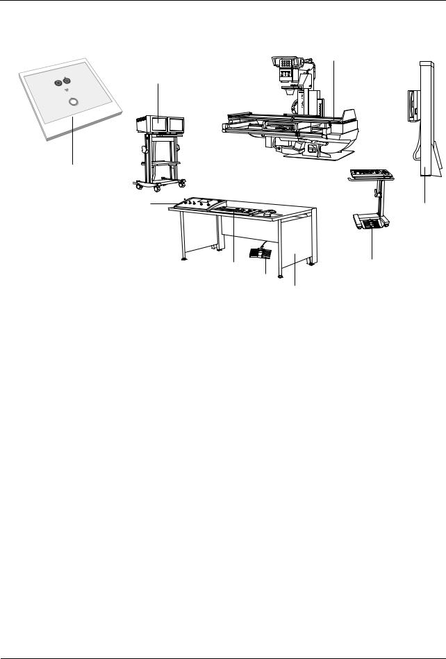
System overview
(1)
(3)
AXIOM
(2)
(4)
(9)
(8)
(5)
(6)
(7)
(1)ICONOS R200 examination unit
(2)Generator ON/OFF console
(3)Monitor trolley (optional)
(4)System remote control console
(5)FLUOROSPOT Compact keyboard
(6)Foot switch for fluoroscopy and radiography
(7)Desk (optional) for operating consoles
(8)Tableside control console with foot switch for fluoroscopy and radiography (optional)
(9)Bucky wall unit (optional)
AXIOM Iconos R200 |
AXD3-340.620.13.01.02 |
7 / 44 |
System Overview
System Description
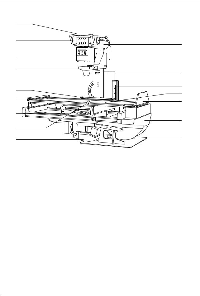
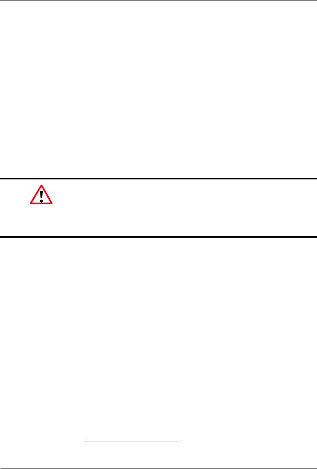
Unit overview
(9)
(8)
(10)
(7)
(6)
(11)
AXIOM
(12)
(5)
(13)
(4)
(14)
(3)
(15)
(2)
(1) |
(16) |
(1)Image intensifier TV system with safety shut-off device
(2)Handgrip (at the front), adjustable
(3)Cassette spotfilm device or I.I. receptor unit with tableside control panel and removable scattered radiation grid
(4)Grip protection strip (head end), detachable
(5)Handgrip strip (located on back), adjustable, secure in all patient positions
(6)Compression device (optional)
for inserting a compression cone, continuously adjustable compression force
(7)Collimator with automatic format collimation and numerical format indication, with integrated motor-driven additional Cu filters, motor-driven adjustable semi-transparent filters (optional)
(8)X-ray tube assembly
air-cooled, partly enclosed, can be swivelled
(9)Handle for swivelling the tube assembly
(10)Tube assembly stand on the longitudinal carriage
coupled with the spotfilm device by centering rod, axially swivelling, telescopic (SID 115cm and 150cm)
(11)Longitudinal carriage with attached tube assembly stand
motorized longitudinal travel, precisely controllable speed
8 / 44 |
AXD3-340.620.13.01.02 |
Operator Manual |

System Overview
System Description
(12)Tomographic height display (option) with laser line light localizer
(13)Tabletop with flat accessory rails motor-driven longitudinal and transverse travel
(14)Footboard
adjustable for use as seat,
with attachment points for foot restraints,
can be changed over from foot end to head end.
(15)Table frame
motor-driven adjustable in height, can be tilted + 90°/-17°
(16)Unit base with tilting drive on installation plate
AXIOM Iconos R200 |
AXD3-340.620.13.01.02 |
9 / 44 |

System Overview
System Description
10 / 44 |
AXD3-340.620.13.01.02 |
Operator Manual |

System Overview
Protective Measures
Emergency Procedures
Warning
Due to the complexity of the system, the loss of X-ray imaging or other system functions during an examination or procedure can not be completely excluded.
Risk of failure during interventions
Consider therefore the need to establish emergency procedures in such cases.
Cleaning and disinfection
Caution
Use of harsh cleaning agents, liquids or sprays.
Risk of electrical hazard or damage to the system
Use only substances for cleaning and disinfection, which are recommended.
Do not let cleaning liquids seep into the openings of the system (e.g. air openings, gaps between covers).
Observe the following cleaning and disinfection instructions.
AXIOM Iconos R200 |
AXD3-340.620.13.01.02 |
11 / 44 |
System Overview
Protective Measures
Radiation protection zones
Position and size of the main operating area
Horizontal patient table:
x
107
200
90
60
60
Main operating area
Dimensions in cm
12 / 44 |
AXD3-340.620.13.01.02 |
Operator Manual |
System Overview
Protective Measures
Vertical patient table:
x
200 140
x
107
40
60
60
Main operating area
Dimensions in cm
AXIOM Iconos R200 |
AXD3-340.620.13.01.02 |
13 / 44 |
System Overview
Protective Measures
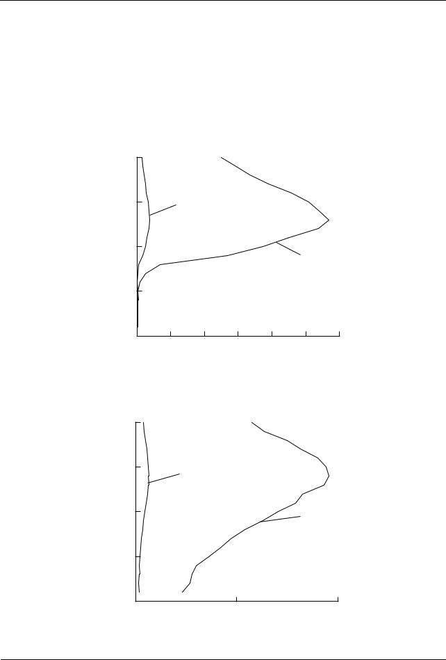
Stray radiation in the main operating area according to DIN EN 60601-1-3
Tolerance of the air kerma measurements ± 5%
Characteristic A and C: continuous fluoroscopy 63kV, 0.8mA (antiisowatt)
Characteristic B and D: continuous fluoroscopy 110kV, 3mA
Patient table horizontal
Height above floor cm
200 |
|
|
|
|
|
|
|
150 |
|
|
A |
|
|
|
|
100 |
|
|
|
|
|
B |
|
|
|
|
|
|
|
|
|
50 |
|
|
|
|
|
|
|
|
|
|
|
|
|
|
Air kerma |
0 |
|
|
|
|
|
|
mGy/h |
0 |
1 |
2 |
3 |
4 |
5 |
6 |
Patient table vertical |
|
|
|
Height above floor |
|
||
cm |
|
|
|
200 |
|
|
|
150 |
|
C |
|
|
|
|
|
100 |
|
|
D |
|
|
|
|
50 |
|
|
|
|
|
|
Air kerma |
0 |
|
|
mGy/h |
0 |
1 |
2 |
|
14 / 44 |
|
AXD3-340.620.13.01.02 |
Operator Manual |
System Overview
Protective Measures
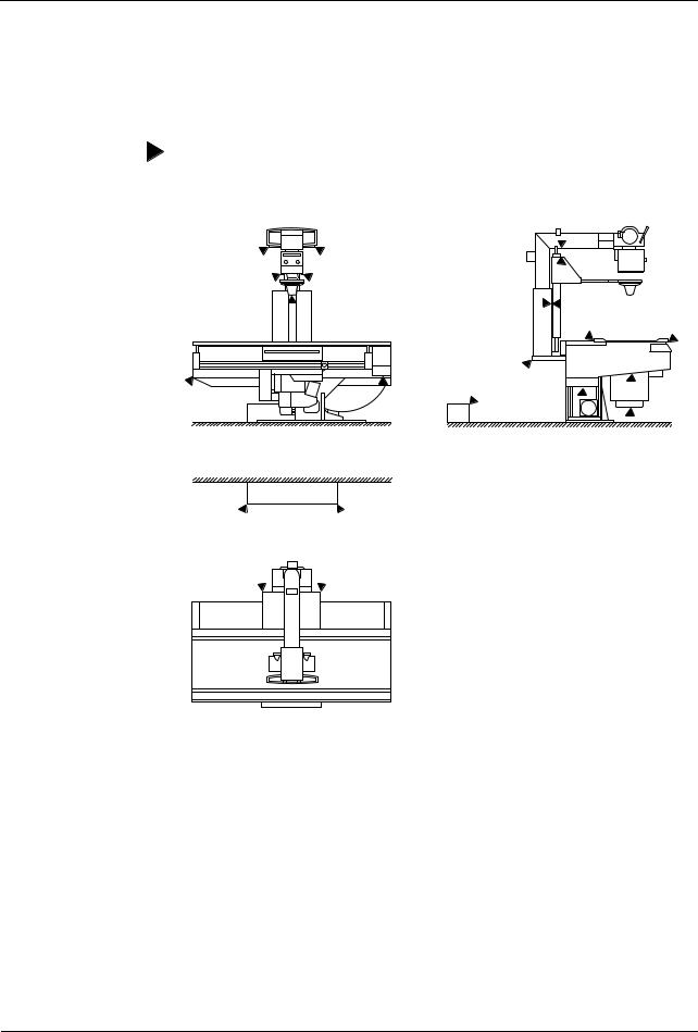
Mechanical safety
Danger zones with unit in horizontal position
The places marked in the illustrations show possible danger zones at which the patient or operator can be injured.
AXIOM Iconos R200 |
AXD3-340.620.13.01.02 |
15 / 44 |

System Overview
Protective Measures
Danger zones with unit in vertical position1
The places marked in the illustration indicate possible danger points where the patient or operating personnel can be injured.
x
 Danger zone
If the patient is located in the danger zone, it must always be ensured that the operating personnel are in the room and within reach of an emergency stop. If the operating personnel leaves the room and/or moves out of reach of an emergency stop, then the patient has to be moved out of the danger zone.
Warning signs
Special danger zones are marked on the unit with a warning sign.
This warning sign is a reference to a possible risk of injury by crushing for the patient and/or examiner.
This warning sign shows the position of the patient table in cardiopulmonary reanimation (CPR) with pressure compression up to 500N (50kg).
1 Between -90° and +90°, depending on the system version
16 / 44 |
AXD3-340.620.13.01.02 |
Operator Manual |
System Overview
Protective Measures
Grip locations
Warning
When handling the system correctly as well as when positioning the patient, operators and patients should use only the grip locations
provided for this purpose.
The following grip locations are provided:
1 handgrip (front)
Grip protection strip (head end)
Handgrip strip (back)
Ensure that the handgrip strip, the grip protection strip and the handgrip are always attached.
If these grip locations cannot be used:
Pay special attention to the stated possibilities of crushing between moving parts and their guide openings.
Ensure during the examination that the patient under no circumstances holds on to the edges of the patient table.
Not intended as gripping point:
The handle for turning the tube assembly must not be used as grip location or hold for the patient.
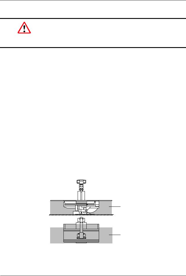
Danger zones
The dotted areas mark the danger zone, where no objects must be located during tilting.
Danger zone
Movement range of the positioning table
Prior to activating any movements of the unit, especially tilting of the unit, make sure that there are no objects such as stairs, steps, stands, waste containers, instrument tables, beds, gurneys, monitor support systems, operating consoles or the like in its movement range.
AXIOM Iconos R200 |
AXD3-340.620.13.01.02 |
17 / 44 |

System Overview
Protective Measures
These objects are not detected by the collision monitoring of the unit. Avoiding collisions of the unit with these objects is subject to the operator’s duty to take care.
If a collision of the unit with a rigid obstacle (e.g. step) has occurred,
press one of the red emergency stop buttons,
rescue the patient,
Warning
Under no circumstances must the unit be tilted down further or tilted up, since externally invisible, but safety-relevant damage to the tilting drive may occur. Severe consequential damage including personal damage cannot be excluded in this case.
immediately notify the SIEMENS Uptime Service.
Avoid standing or sitting immediately adjacent to the system and especially do not sit next to the system with your legs or knees under the cross-beam at the head or foot end of the table.
Take care that during system movements no one is in the area between the unit base and table.
Take care that with the footboard attached there is a risk of collision with the extended cone (optional) when the tabletop and / or the longitudinal carriage are moving.
Do not grasp in the loading shaft of the spotfilm device because of the risk of crushing.
Patient positioning
All safety-related equipment must be installed and operable. In particular the handgrip strips (head end and lateral), handgrip, footboard, foot restraints, compression belt and shoulder supports.
The patient’s hands, arms, legs, head and hair must not extend unsecured beyond the edge of the tabletop.
Observe the patient while moving the tabletop and in system movements and take care that any catheter is correctly located.
In examinations with the table tilted up vertically, the footboard serves as an adjustable step or seat.
–Ensure that the footboard is locked together with the tabletop on both sides.
–Check the firm location of the footboard.
18 / 44 |
AXD3-340.620.13.01.02 |
Operator Manual |
System Overview
Protective Measures
Patient positioning with unit in vertical position
During examinations with the unit in the upright position there is a risk of crush injuries to the patient if the X-ray system (stand with tube unit/receptor unit with image intensifier) is moved in the longitudinal direction.
Position the X-ray system approximately in the acquisition position.
Move the patient into the acquisition position.
Set the X-ray system to object height. Always watch the patient when initiating this movement.
Remote compression (optional)
The motor-driven compression device requires special care on the part of the examiner for the applied compression forces, especially in the case of frail (e.g. infants), sick and elderly patients.
Observe especially that both an increased risk of crushing for the patient with consequential injury and considerable mechanical shearing forces with risk of damage can occur between the compression cone and attached accessories, e.g. shoulder supports, lateral support (optional) or motor-driven infant cradle holder (optional) by collision during the motor-driven tabletop movement.
When moving the compression carriage into the lowest position, the carriage may collide with the patient’s hand on the grip protection strip.
– Use extreme caution when actuating the cone movement.
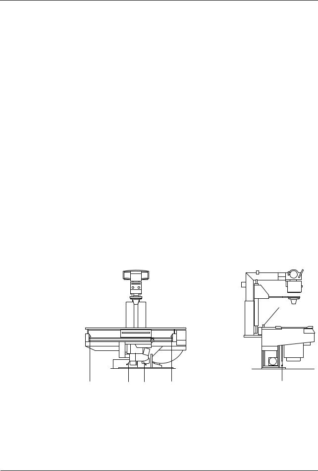
Safety devices
(1)
(2) |
(3) |
(3) |
(2) |
(3) |
(1)Switch rail between tabletop and stand
(2)Switch rails in each case at the end of the travel of the spotfilm unit
(3)Safety switching sensors on the image intensifier TV device (2 sensors))
AXIOM Iconos R200 |
AXD3-340.620.13.01.02 |
19 / 44 |
System Overview
Protective Measures
On activation of one of the safety devices (shutdown devices) all system movements stop and are blocked.
This means that one cannot move out from the blockage oneself.
If it is not possible to remove the obstruction causing the problem, call in the Siemens Uptime Services.
Movements are possible again only after one of the safety devices has be deactivated.
Possible collisions of the system with a ceiling-mounted support1
System movements are possible only if the ceiling-mounted support is in its park position or if the bypass switch is activated if necessary.
Prior to actuating system movements with the bypass switch activated, verify that no collision can take place with the ceiling-mounted support, the X-ray tube assembly or the collimator. (No collision monitoring.)
Warning
If system movements are possible even though the ceiling-mounted support is not in the park position and the bypass switch is not activated,
immediately press the emergency shutdown button and notify the SIEMENS Uptime Service.
Measures for avoiding equipment damage
Before activating system movements, especially tilting the table, make sure that the movement range is free of obstructions.
Move especially monitor support systems, operating consoles, gurneys, beds and instrument tables out from the tilting range of the table and remove chairs, steps, stands, waste containers and similar objects from the movement area. (No collision monitoring.)
Do not place any objects or consumable material on the cover of the table support, on the spotfilm device and on the longitudinal guides of the stand carriage.
–Considerable forces which can damage these objects in the area of movement of the systems arise during movements of the spotfilm device or of the tabletop.
Do not place any loose objects anywhere on the table.
–These objects could fall down when the table is tilted, causing injury or damage.
1 optional
20 / 44 |
AXD3-340.620.13.01.02 |
Operator Manual |

System Overview
Protective Measures
Do not stand at any place on the spotfilm device or on the covers of the table support outside the marked areas provided for this.
–The covers can be deformed.
Components located underneath them are damaged and thus lead to operating disturbances.
Place no objects on the operating areas of the control consoles and the tableside control.
Caution
Unintentional activation of control elements for movements
Collision with patient, operator or equipment
Do not load the remote console with any objects, accessories, folders or documents.
To avoid unintentional activation of control elements for movements concerning bed exposure, please adhere to the following workflow:
Select aquisition mode Bed exposure at the generator control console.
Tilt the system and move it to the correct SID.
Rotate the tube assembly accordingly.
Position the patient.
Control patient and system.
Don’t let patient stay in system area during absence of operator.
In vertical table positions do not use the stand column, the tube assembly support arm, the tube assembly cover or the primary collimator as seat or support.
–This unallowed loading can lead to material breakage and damage to bearings.
Never put contrast medium cups or open containers with liquid or pasty contents on the unit, on the remote console or on the control cabinets.
–Contrast medium can spill, leak or overflow into system parts and lead to operational disturbances of the unit or to misinterpretation of exposures.
When storing contrast medium in the cup holder on the compression carriage, use only cups with a maximum volume of 0.25 liter made of unbreakable materials, i.e. under no circumstances glass or porcelain.
–Remove contrast medium traces immediately!
Measures for avoiding unwanted radiation
Before starting system movements make sure that the foot switch for fluoroscopy and radiography (optional) in the examination room is not in the travel range of the image intensifier light distribution system.
AXIOM Iconos R200 |
AXD3-340.620.13.01.02 |
21 / 44 |

System Overview
Protective Measures
Safety-relevant parts subject to wear
This system contains no safety-relevant parts subject to wear.
Maintenance intervals
Maintenance must be performed annually in order to ensure the safety and functioning ability of the system.
If you have not concluded a maintenance contract, please notify the Siemens Uptime Service on time.
CAREWATCH
Display data
At the start of fluoroscopy/acquisition the following system parameters are displayed in the lower right area of the live monitor:
1st line
– Display of the prefilter in fluoroscopy
2nd line
– Display of the prefilter in radiography With the area dose product meter (optional)1
3rd line
– Area dose product in cGycm²
4th line
During fluoroscopy
– Display of the patient entrance dose2 in mGy/min
In the radiation pauses
–the percentage of the patient entrance dose reached related to a configurable limit1 of 0.5 to 5 Gy or
–the accumulated patient entrance dose in mGy is displayed.
The measuring device must be calibrated at regular intervals. This is done within the scope of a maintenance contract. If no maintenance contract have been concluded, the measuring device can be calibrated by the Siemens Uptime Service of the manufacturer.
1can be configured by the SIEMENS Uptime Service
2standardized to 30 cm above the tabletop
22 / 44 |
AXD3-340.620.13.01.02 |
Operator Manual |
Loading...