


 Loading...
Operation/Programming 08/2002 Edition
ManualTurn
SINUMERIK 840D/810D

SINUMERIK 840D/810D
ManualTurn
Operation/Programming
Valid for |
|
|
Control |
Software version |
|
SINUMERIK 840D |
|
6 |
SINUMERIK 840DE (export version) |
6 |
|
SINUMERIK 840D powerline |
6 |
|
SINUMERIK 840DE powerline |
6 |
|
SINUMERIK 810D powerline |
6 |
|
SINUMERIK 810DE powerline |
6 |
|
08.02 Edition
Introduction
Operation
Preparatory Functions for Machining
Turning Simple
Contours
Turning with Cycles
Turning any Contours
Program Creation with EasyStep and G Code
Parts Program
Management
General Functions
Intervention in the
Machining Process
Alarms and Messages
Examples
Appendix
1
2
3
4
5
6
7
8
9
10
11
12
A

SINUMERIK® Documentation
Printing history
Brief details of this edition and previous editions are listed below.
The status of each edition is shown by the code in the "Remarks" column.
Status code in the "Remarks" column: |
|
|
A .... |
New documentation. |
|
B .... |
Unrevised edition with new Order No. |
|
C .... |
Revised edition with new status. |
|
|
If factual changes have been made on the page since the last edition, this is indicated by a |
|
|
new edition coding in the header on that page. |
|
Edition |
Order No. |
Remarks |
06.97 |
6FC5298-2AD00-0BP0 |
A |
12.97 |
6FC5298-2AD00-0BP1 |
C |
07.98 |
6FC5298-2AD00-0BP2 |
C |
02.00 |
6FC5298-5AD00-0BP0 |
C |
08.00 |
6FC5298-5AD00-0BP1 |
C |
08.02 |
6FC5298-6AD00-0BP0 |
C |
This manual is included in the documentation available on CD ROM (DOCONCD) |
||
Edition |
Order No. |
Remarks |
11.02 |
6FC5 298-6CA00-0BG3 |
C |
Trademarks
SIMATIC®, SIMATIC HMI®, SIMATIC NET®, SIROTEC®, SINUMERIK® and SIMODRIVE® are registered trademarks of Siemens AG. Other product names used in this documention may be trademarks which, if used by third parties, could infringe the rights of their owners.
Further information is available on the Internet under: http:/www.a&d.siemens.de/sinumerik
This publications was produced with WinWord V8.0 and Designer V7.0. The reproduction, transmission or use of this document or its contents is not
permitted without express written authority. Offenders will be liable for damages. All rights, including rights created by patent grant or registration of a utility model or design, are reserved.
© Siemens AG, 1997, 1998, 2000, 2002. All rights reserved
Other functions not described in this documentation might be executable in the control. This does not, however, represent an obligation to supply such functions with a new control or when servicing.
We have checked that the contents of this document correspond to the hardware and software described. Nonetheless, differences might exist and therefore we cannot guarantee that they are completely identical. The information contained in this document is, however, reviewed regularly and any necessary changes will be included in the next edition. We welcome suggestions for improvement.
Subject to change without prior notice
Order No. 6FC5298-6AD00-0BP0 |
Siemens Aktiengesellschaft |
Printed in Germany |
|

0 |
|
08.02 |
|
Contents |
|
0 |
Contents |
|
|
|
|
||
|
|
Introduction |
|
1-13 |
||
|
|
|
||||
|
1.1 |
The ManualTurn product........................................................................................... |
|
1-14 |
||
|
1.2 |
Operator notes .......................................................................................................... |
|
1-15 |
||
|
1.3 |
Switching on/switching off ......................................................................................... |
|
1-16 |
||
|
|
Operation |
|
|
2-17 |
|
|
2.1 |
Operator panels ........................................................................................................ |
|
2-18 |
||
|
2.2 |
Machine control panel ............................................................................................... |
|
2-21 |
||
|
2.3 |
Mini handheld unit ..................................................................................................... |
|
2-25 |
||
|
2.4 |
Graphics interface..................................................................................................... |
|
2-27 |
||
|
2.5 |
Operating system ...................................................................................................... |
|
2-29 |
||
|
2.5.1 |
Operating modes....................................................................................................... |
|
2-30 |
||
|
2.5.2 |
Important function keys ............................................................................................. |
|
2-32 |
||
|
2.5.3 |
Important soft keys.................................................................................................... |
|
2-33 |
||
|
2.5.4 |
Pocket calculator....................................................................................................... |
|
2-34 |
||
|
2.5.5 |
Absolute and incremental dimensions ...................................................................... |
|
2-36 |
||
|
2.5.6 |
Angle reference system ............................................................................................ |
|
2-37 |
||
|
2.5.7 |
Tool and cutting data................................................................................................. |
|
2-38 |
||
|
|
Preparatory Functions for Machining |
|
3-41 |
||
|
3.1 |
Approach reference points ........................................................................................ |
|
3-42 |
||
|
3.2 |
Setup......................................................................................................................... |
|
3-44 |
||
|
3.3 |
Incremental feed mode ............................................................................................. |
|
3-45 |
||
|
3.4 |
Offsets....................................................................................................................... |
|
3-47 |
||
|
3.4.1 |
General notes............................................................................................................ |
|
3-47 |
||
|
3.4.2 |
Preset........................................................................................................................ |
|
3-48 |
||
|
3.4.3 |
Manual offset............................................................................................................. |
|
3-49 |
||
|
3.4.4 |
Delete manual offset ................................................................................................. |
|
3-50 |
||
|
3.4.5 |
Zero offset................................................................................................................. |
|
3-51 |
||
|
3.5 |
Spindle speed limitation ............................................................................................ |
|
3-52 |
||
|
3.6 |
Oriented spindle stop ................................................................................................ |
|
3-53 |
||
|
3.7 |
C axis mode .............................................................................................................. |
|
3-54 |
||
|
3.8 |
Tool ........................................................................................................................... |
|
3-55 |
||
|
3.8.1 |
Enter tool offset data ................................................................................................. |
|
3-55 |
||
|
3.8.2 |
Selecting/deselecting tool offset................................................................................ |
|
3-57 |
||
|
3.8.3 |
Measure tool ............................................................................................................. |
|
3-58 |
||
|
3.8.4 |
Tool wear compensation........................................................................................... |
|
3-60 |
||
|
3.9 |
Measuring system changeover inch/metric............................................................... |
|
3-61 |
||
|
|
|
|
|
|
|
Siemens AG, 2002. All rights reserved |
0-5 |
SINUMERIK 840D/810D Operator's Guide ManualTurn (BAM) – 08.02 Edition |

0 |
|
Contents |
08.02 |
|
0 |
|
Turning Simple Contours |
4-63 |
|
|
4.1 |
Turning in manual mode............................................................................................ |
4-64 |
|
4.2 |
Turning with path dimension input............................................................................. |
4-66 |
|
4.2.1 |
Turning with STRAIGHT mode.................................................................................. |
4-67 |
|
4.2.2 |
Turning with CONICAL mode.................................................................................... |
4-69 |
|
4.2.3 |
Turning with CIRCLE mode....................................................................................... |
4-71 |
|
4.3 |
Turning with the contour handwheel and JOG keys +/–............................................ |
4-75 |
|
Turning with Cycles |
5-79 |
|
|
5.1 |
General notes............................................................................................................ |
5-80 |
|
5.2 |
Turning cycles in CYCLE mode................................................................................. |
5-81 |
|
5.2.1 |
Thread cutting ........................................................................................................... |
5-81 |
|
5.2.2 |
Controlling thread cutting operations......................................................................... |
5-87 |
|
5.2.3 |
Re-working a thread .................................................................................................. |
5-88 |
|
5.2.4 |
Undercuts Form E and F ........................................................................................... |
5-89 |
|
5.2.5 |
Thread undercuts ...................................................................................................... |
5-91 |
|
5.2.6 |
Drilling in longitudinal axis (center)............................................................................ |
5-93 |
|
5.2.7 |
Hole circle drilling ...................................................................................................... |
5-97 |
|
5.3 |
Stock removal/grooving cycles in STOCK REMOVAL mode.................................. |
5-100 |
|
5.3.1 |
Stock removal cycles............................................................................................... |
5-100 |
|
5.3.2 |
Grooving cycles ....................................................................................................... |
5-105 |
|
Turning any Contours (Free Contour Input) |
6-111 |
|
|
6.1 |
General notes.......................................................................................................... |
6-112 |
|
6.2 |
Create new contour ................................................................................................. |
6-113 |
|
6.3 |
Symbolic representation of contour......................................................................... |
6-114 |
|
6.4 |
Graphic representation of contour........................................................................... |
6-115 |
|
6.5 |
Create contour elements ......................................................................................... |
6-116 |
|
6.6 |
Editing contour elements......................................................................................... |
6-119 |
|
6.7 |
Stock removal against contour ................................................................................ |
6-122 |
|
6.8 |
Machining residual material..................................................................................... |
6-126 |
|
6.9 |
Single-cycle machining............................................................................................ |
6-127 |
|
Program Creation with EasyStep and G Code |
7-129 |
|
|
7.1 |
General notes.......................................................................................................... |
7-130 |
|
7.2 |
Creating a machining sequence.............................................................................. |
7-131 |
|
7.3 |
Display machining sequence................................................................................... |
7-132 |
|
7.4 |
Program steps ......................................................................................................... |
7-133 |
|
7.4.1 |
Inserting new program step..................................................................................... |
7-133 |
|
7.4.2 |
Special functions ..................................................................................................... |
7-134 |
|
|
|
|
0-6 |
Siemens AG, 2002. All rights reserved |
SINUMERIK 840D/810D Operator's Guide ManualTurn (BAM) – 08.02 Edition |
|
0 |
|
08.02 |
|
Contents |
|
|
0 |
|
|
|
7.4.3 |
Insert G code step |
|
7-135 |
|
|||
|
|
|
|
||||||
|
|
7.4.4 |
Changing program steps......................................................................................... |
|
7-135 |
|
|||
|
|
7.4.5 |
Program editor ........................................................................................................ |
|
7-136 |
|
|||
|
|
7.5 |
Switching off the program ....................................................................................... |
|
7-137 |
|
|||
|
|
7.6 |
Start machining sequence....................................................................................... |
|
7-137 |
|
|||
|
|
7.7 |
Single-step mode (single block).............................................................................. |
|
7-138 |
|
|||
|
|
7.8 |
Block search............................................................................................................ |
|
7-138 |
|
|||
|
|
7.9 |
Tool nose radius compensation .............................................................................. |
|
7-139 |
|
|||
|
|
7.10 |
G code programming .............................................................................................. |
|
7-141 |
|
|||
|
|
7.10.1 |
Select program view................................................................................................ |
|
7-141 |
|
|||
|
|
7.10.2 |
G code editor........................................................................................................... |
|
7-143 |
|
|||
|
|
7.10.3 |
Create new parts program ...................................................................................... |
|
7-145 |
|
|||
|
|
7.10.4 |
Inserting program blocks......................................................................................... |
|
7-145 |
|
|||
|
|
7.10.5 |
Editing program blocks............................................................................................ |
|
7-146 |
|
|||
|
|
|
Parts Program Management |
|
8-149 |
|
|||
|
|
8.1 |
General ................................................................................................................... |
|
8-150 |
|
|||
|
|
8.2 |
Select a file.............................................................................................................. |
|
8-151 |
|
|||
|
|
8.3 |
Delete a file ............................................................................................................. |
|
8-151 |
|
|||
|
|
8.4 |
Storing thread undercut and thread cycles ............................................................. |
|
8-152 |
|
|||
|
|
8.5 |
Insert a contour in EasyStep machining sequence ................................................. |
|
8-152 |
|
|||
|
|
8.6 |
Rename/copy file .................................................................................................... |
|
8-153 |
|
|||
|
|
8.7 |
Read out a file to an external medium .................................................................... |
|
8-153 |
|
|||
|
|
8.8 |
Read in a file ........................................................................................................... |
|
8-154 |
|
|||
|
|
8.9 |
Error/transmission log ............................................................................................. |
|
8-154 |
|
|||
|
|
|
General Functions |
|
9-155 |
|
|||
|
|
9.1 |
Simulation and simultaneous recording .................................................................. |
|
9-156 |
|
|||
|
|
9.1.1 |
Simulation ............................................................................................................... |
|
9-158 |
|
|||
|
|
9.1.2 |
Simultaneous recording .......................................................................................... |
|
9-159 |
|
|||
|
|
9.1.3 |
Dry run..................................................................................................................... |
|
9-159 |
|
|||
|
|
9.2 |
Teach In .................................................................................................................. |
|
9-161 |
|
|||
|
|
9.2.1 |
Selecting the Teach In function............................................................................... |
|
9-161 |
|
|||
|
|
9.2.2 |
Deselecting "Teach In"............................................................................................ |
|
9-162 |
|
|||
|
|
9.2.3 |
Continuing "Teach In".............................................................................................. |
|
9-162 |
|
|||
|
|
9.2.4 |
Transferring machining steps to system ................................................................. |
|
9-163 |
|
|||
|
|
9.2.5 |
Transferring auxiliary functions to system............................................................... |
|
9-165 |
|
|||
|
|
9.3 |
Standard CNC operation......................................................................................... |
|
9-166 |
|
|||
|
|
|
Intervention in the Machining Process |
10-167 |
|
||||
|
|
10.1 |
Aborting a machining operation ............................................................................ |
|
10-168 |
|
|||
|
|
|
|
|
|
|
|
|
|
|
Siemens AG, 2002. All rights reserved |
|
0-7 |
||||||
|
SINUMERIK 840D/810D Operator's Guide ManualTurn (BAM) – 08.02 Edition |
|
|||||||

0 |
|
Contents |
08.02 |
|
0 |
|
10.2 |
.........................................................................................................Repositioning |
10-169 |
|
10.3 |
Saving manual offset with "Store offset" function.................................................. |
10-170 |
|
Alarms and Messages |
11-171 |
|
|
11.1 |
Alarms and messages in ManualTurn cycles........................................................ |
11-172 |
|
11.1.1 |
Error handling in cycles ......................................................................................... |
11-172 |
|
11.1.2 |
Overview of cycle alarms....................................................................................... |
11-172 |
|
11.1.3 |
Messages in cycles ............................................................................................... |
11-173 |
|
11.2 |
Alarms with ManualTurn........................................................................................ |
11-174 |
|
11.2.1 |
Overview of alarms................................................................................................ |
11-174 |
|
11.2.2 |
Selecting the alarm/message overview................................................................. |
11-174 |
|
11.2.3 |
Description of alarms............................................................................................. |
11-175 |
|
Examples |
|
12-183 |
|
12.1 |
Example 1: External machining with groove and thread ....................................... |
12-184 |
|
12.2 |
Example 2: External machining with sphere ......................................................... |
12-189 |
|
12.3 |
Example 3: External machining with thread undercuts and grooves..................... |
12-194 |
|
12.4 |
Example 4: External machining with thread undercut and groove ........................ |
12-200 |
|
Appendix |
|
A-207 |
|
A |
Abbreviations........................................................................................................... |
A-208 |
|
B |
Terms ...................................................................................................................... |
A-211 |
|
C |
References .............................................................................................................. |
A-214 |
|
D |
Index........................................................................................................................ |
A-227 |
|
|
|
|
0-8 |
Siemens AG, 2002. All rights reserved |
SINUMERIK 840D/810D Operator's Guide ManualTurn (BAM) – 08.02 Edition |

0 |
|
08.02 |
Preface |
|
0 |
Preface
Organization of documentation
Reader group
Validity
Hotline
Internet address
SINUMERIK 840D powerline
SINUMERIK 810D powerline
Standard scope
The SINUMERIK documentation is organized on 3 different levels:
•General Documentation
•User Documentation
•Manufacturer/Service Documentation
This manual is intended for users (operators) of turning machines with SINUMERIK 840D/810D.
The Operator Control/Programming Guide is valid for ManualTurn SW 6.2 with
•SINUMERIK 810D (SW 6.3 and higher)
•SINUMERIK 840D (SW 6.3 and higher)
Please address any questions to the following hotline: A&D Technical Support
Phone: ++49-(0)180-5050-222
Fax: ++49-(0)180-5050-223 E-Mail: adsupport@siemens.com
If you have any questions (suggestions, corrections) concerning the documentation, please fax or e-mail them to the following address: Fax: ++49-(0)9131-98-2176
Fax form provided at the end of the document E-mail: motioncontrol.docu@erlf.siemens.de
http://www.ad.siemens.de/sinumerik
From 09.2001 onwards, the SINUMERIK 840D powerline and SINUMERIK 840DE powerline will be available with enhanced performance. See the hardware description below for a list of the available powerline modules:
References: /PHD/, Configuring Manual SINUMERIK 840D
From 12.2001 onwards, the SINUMERIK 810D powerline and SINUMERIK 810DE powerline will be available with enhanced performance. See the hardware description below for a list of the available powerline modules:
References: /PHC/, Configuring Manual SINUMERIK 810D
This Operating/Programming Guide describes only the functionality of the ManualTurn user interface. A description of add-on features or modifications made by the machine builder are not included in this guide.
For more detailed information on SINUMERIK 840D/810D publications and other publications covering all SINUMERIK controls (e.g. universal interface, measuring cycles...), please contact your local Siemens office.
Siemens AG, 2002. All rights reserved |
0-9 |
SINUMERIK 840D/810D Operator's Guide ManualTurn (BAM) – 08.02 Edition |

0 |
|
Preface |
08.02 |
|
0 |
|
|
|
Other functions not described in this documentation might be |
|
|
|
|
|
executable in the control. This does not, however, represent an |
|
|
|
|
|
obligation to supply such functions with a new control or when |
|
|
|
|
|
servicing. |
|
|
|
|
Basis |
Your SIEMENS 840D/810D with ManualTurn is state of the art and is |
||
|
|
|
manufactured in accordance with recognized safety regulations, |
|
|
|
|
|
standards and specifications. |
|
|
|
|
Add-on equipment |
Using special add-on equipment and expanded configurations from |
||
|
|
|
SIEMENS, SIEMENS controls can be adapted to suit your specific |
||
|
|
|
application. |
|
|
|
|
Personnel |
Only authorized and reliable personnel with the relevant training |
||
|
|
|
must be allowed to handle the control. Nobody without the necessary |
||
|
|
|
training must be allowed to work on the control, not even for a short |
||
|
|
|
time. |
|
|
|
|
|
The responsibilities of the personnel employed for setting, operating |
||
|
|
|
and maintenance must be clearly defined and supervised. |
|
|
|
|
Behavior |
Before the control is started up, it must be ensured that the Operator's |
||
|
|
|
Guide has been read and understood by the personnel responsible. |
||
|
|
|
The operating company is also responsible for constantly monitoring |
||
|
|
|
the overall technical state of the control (faults and damage apparent |
||
|
|
|
from the outside and changes in response). |
|
|
|
|
Service |
Repairs must only be carried out in accordance with the information |
||
|
|
|
given in the Service and Maintenance Guide by personnel trained |
||
and qualified in the relevant field. The relevant safety regulations must be observed.
The following is contrary to the intended purpose and exonerates the manufacturer from any liability:
• Any use whatsoever beyond or deviating from the application stated in the above points.
• If the control is not in perfect technical condition, or is operated without awareness for safety or the dangers involved or without observing the instructions given in the instruction manual.
• If faults that can reduce safety are not remedied before the control is started up.
• Any modification, overriding or deactivation of equipment on the control used for the perfect functioning, unrestricted use or active and passive safety.
0-10 |
Siemens AG, 2002. All rights reserved |
SINUMERIK 840D/810D Operator's Guide ManualTurn (BAM) – 08.02 Edition |
0 |
|
08.02 |
Preface |
|
0 |
Structure of the document
Warnings
This can result in unforeseen dangers for:
•the health and life of people,
•the control, machine and other property of the operating company and user.
The following information blocks marked by symbols are used in this document:
Function
Sequence of operations
Explanation of parameters
Additional notices
Software option
The function described is a software option, i.e. the function is only executable on the control if you have acquired that option.
The following five warnings are used with graded severity.
Danger
Indicates an imminently hazardous situation which, if not avoided, will result in death or serious injury or in substantial property damage.
Warning
Indicates a potentially hazardous situation which, if not avoided, could result in death or serious injury or in substantial property damage.
Caution
Used with the safety alert symbol indicates a potentially hazardous situation which, if not avoided, may result in minor or moderate injury or in property damage.
Siemens AG, 2002. All rights reserved |
0-11 |
SINUMERIK 840D/810D Operator's Guide ManualTurn (BAM) – 08.02 Edition |
0 |
|
Preface |
08.02 |
|
0 |
Caution
Reference to other literature
Used without safety alert symbol indicates a potentially hazardous situation which, if not avoided, may result in property damage.
Notice
Used without the safety alert symbol indicates a potential situation which, if not avoided, may result in an undesirable result or state.
This marking appears wherever specific information can be found in more detailed reference literature.
References:
The Appendix in this Operator's Guide contains a complete list of references.
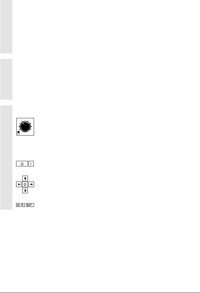
The following symbols are used for the operating elements:
Selection of an operating mode
Soft key |
Selection via soft key |
|
|
|
Feed Stop/Start keys |
|
Axis/direction selection, e.g. using control stick
JOG keys
0-12 |
Siemens AG, 2002. All rights reserved |
SINUMERIK 840D/810D Operator's Guide ManualTurn (BAM) – 08.02 Edition |

1 |
|
08.02 |
|
Introduction |
|
1 |
Introduction |
|
|
|
|
||
|
The ManualTurn product |
1-14 |
||||
|
1.1 |
|||||
|
1.2 |
Operator notes .......................................................................................................... |
1-15 |
|||
|
1.3 |
Switching on/switching off ......................................................................................... |
1-16 |
|||
|
|
|
|
|
|
|
Siemens AG, 2002. All rights reserved |
1-13 |
SINUMERIK 840D/810D Operator's Guide ManualTurn (BAM) – 08.02 Edition |

1 |
|
Introduction |
08.02 |
|
1 |
|
1.1 The ManualTurn product |
|
|
||
1.1 |
|
The ManualTurn product |
|
|
|
The ManualTurn product with SINUMERIK 840D or SINUMERIK 810D is a CNC (Computerized Numerical Control) for turning machines used predominantly for conventional machining operations. The 810D is simple and reliable to operate so as to facilitate the task of the skilled machinist. All inputs are made in plain text in interactive dialog and displayed graphically for checking purposes, i.e. the lathe operator can examine the motional path of the tool before he starts the program.
The operator panel of the CNC allows you to implement the following basic functions (in conjunction with a machine lathe):
•Setting up and conventional turning with handwheels
•Longitudinal and taper turning, facing with feedrate per revolution and per minute
•Execution of finishing or roughing cuts on elementary contours
•Machining with cycles in single-cycle mode
•Creation of complex contours with the option of removing stock and finishing against the contour (option)
•Creation of parts programs for complete machining using EasyStep programming.
•Automatic creation of parts programs in the Teach In operating mode.
It is advisable to read Chapter 2 "Operation" carefully before working through the other sections.
All further sections are written on the premise that you have read and understood Chapter 2!
1-14 |
Siemens AG, 2002. All rights reserved |
SINUMERIK 840D/810D Operator's Guide ManualTurn (BAM) – 08.02 Edition |

1 |
|
08.02 |
Introduction |
|
1 |
|
|
1.2 Operator notes |
|
1.2Operator notes
Caution
The operator panel/machine control panel may only be opened for servicing purposes by properly qualified personnel.
Danger
Fatal injury may occur if the operator panel/machine control panel is opened when the power supply is still connected.
Warning
Electronic components inside the operator/machine control panel may sustain irreparable electrical damage if they are not handled in the correct manner.
Before you touch any control elements on this operator panel:
Please read through the explanations in this document carefully!
Siemens AG, 2002. All rights reserved |
1-15 |
SINUMERIK 840D/810D Operator's Guide ManualTurn (BAM) – 08.02 Edition |

1 |
|
Introduction |
08.02 |
|
|
1 |
|
1.3 Switching on/switching off |
|
|
|||
1.3 |
|
Switching on/switching off |
|
|||
|
|
|
Function |
|
||
|
|
|
|
|||
|
|
Switching on |
There are various methods by which the control system or the entire |
|||
|
|
|||||
|
|
|
installation can be switched on. |
|
||
|
|
|
It is very important to read the information supplied by the machine |
|||
|
|
|
||||
|
|
|
manufacturer! |
|
||
|
|
|
A power-up display specific to the machine manufacturer appears |
|
||
|
|
|
|
|||
|
|
|
several seconds after the control has powered up. |
|
||
|
|
Switching off |
Before you switch off the control system or the entire installation, |
|
||
|
|
|
please remember: |
|
||
It is very important to read the information supplied by the machine manufacturer!
1-16 |
Siemens AG, 2002. All rights reserved |
SINUMERIK 840D/810D Operator's Guide ManualTurn (BAM) – 08.02 Edition |

2 |
|
08.02 |
|
Operation |
|
2 |
Operation |
|
|
|
|
||
|
Operator panels |
|
2-18 |
|||
|
2.1 |
|
||||
|
2.2 |
Machine control panel .................................................................................................... |
|
2-21 |
||
|
2.3 |
Mini handheld unit .......................................................................................................... |
|
2-25 |
||
|
2.4 |
Graphics interface .......................................................................................................... |
|
2-27 |
||
|
2.5 |
Operating system ........................................................................................................... |
|
2-29 |
||
|
2.5.1 |
Operating modes....................................................................................................... |
|
2-30 |
||
|
2.5.2 |
Important function keys ............................................................................................. |
|
2-32 |
||
|
2.5.3 |
Important soft keys.................................................................................................... |
|
2-33 |
||
|
2.5.4 |
Pocket calculator....................................................................................................... |
|
2-34 |
||
|
2.5.5 |
Absolute and incremental dimensions ...................................................................... |
|
2-36 |
||
|
2.5.6 |
Angle reference system ............................................................................................ |
|
2-37 |
||
|
2.5.7 |
Tool and cutting data................................................................................................. |
|
2-38 |
||
|
|
|
|
|
|
|
Siemens AG, 2002. All rights reserved |
2-17 |
SINUMERIK 840D/810D Operator's Guide ManualTurn (BAM) – 08.02 Edition |
2 |
|
Operation |
08.02 |
|
2 |
|
2.1 Operator panels |
|
|
||
2.1 |
|
Operator panels |
|
|
|
Alternately, you can use one of the following operator panels for the
PCUs:
OP 010
OP 010C
OP 010S with CNC full keyboard OP 032S
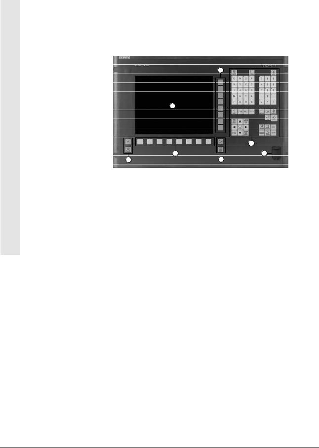
Operator panel OP 010
4
1
.
|
5 |
3 |
6 |
2 |
2 |
Operator panel OP 010
1Monitor
2Monitor keys
3Horizontal soft key menu
4Vertical soft key menu
5Alphanumeric pad
Correction/cursor pad with control keys and input key
6USB interface
2-18 |
Siemens AG, 2002. All rights reserved |
SINUMERIK 840D/810D Operator's Guide ManualTurn (BAM) – 08.02 Edition |
2 |
|
08.02 |
Operation |
|
2 |
|
|
2.1 Operator panels |
|
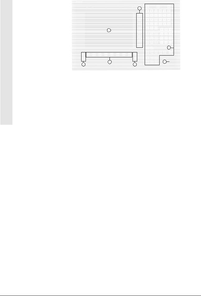
Operator panel OP 010C
4
1 |
. |
5
2 |
3 |
6 |
|
2 |
Operator panel OP 010C
1Monitor
2Monitor keys
3Horizontal soft key menu
4Vertical soft key menu
5Alphanumeric pad
Correction/cursor pad with control keys and input key
6USB interface
Siemens AG, 2002. All rights reserved |
2-19 |
SINUMERIK 840D/810D Operator's Guide ManualTurn (BAM) – 08.02 Edition |

2 |
|
Operation |
08.02 |
|
2 |
|
2.1 Operator panels |
|
|
Slimline operator panel
OP 010S
|
1 |
|
A2 |
2A |
A4 |
|
|
3A
8
Operator panel OP 010S
With CNC full keyboard OP 032S
5
6 |
7 |
Program
Alarm Program Tool
Manager Offset
CNC keyboard OP 032S
1Monitor
2Monitor keys
3Horizontal soft key menu
4Vertical soft key menu
5Alpha pad
6Correction/cursor pad with control keys
7Numeric pad
8USB interface
2-20 |
Siemens AG, 2002. All rights reserved |
SINUMERIK 840D/810D Operator's Guide ManualTurn (BAM) – 08.02 Edition |
2 |
|
08.02 |
Operation |
|
2 |
|
|
2.2 Machine control panel |
|
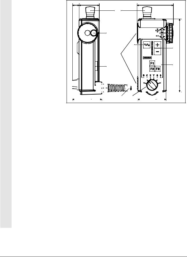
2.2Machine control panel
General notes
Example
X -
|
Z - |
|
|
XZ |
|
|
Z + |
|
|
|
off |
|
|
||
|
|
|
|
|
|
|
|
X +
Operations on the machine tool such as axis traversal or program start can only be initiated via a machine control panel.
The machine control panel is configured and supplied by the machine tool manufacturer.
Please refer to the operating manual supplied by the machine tool manufacturer for details of which panel control elements are required for your application and a description of their functionality.
The following description is based on an example configuration.
Operating modes
Depending on your requirements, operating modes MANUAL,
STRAIGHT, CONICAL, CIRCLE, CYCLE, STOCK REMOVAL,
CONTOUR and PROGRAM can be activated via
•an operating mode switch or
•the vertical soft key menu on the operator panel or
•illuminated keys.
Traversing directions
Control stick with rapid traverse key
The control stick allows axes X and Z to be traversed paraxially and at angles of 45°. The control stick is active in Setup mode and in the above mentioned operating modes.
•Illuminated keys.
As an alternative to the control stick, you can also use the illuminated keys to select the traversing direction.
The traversing velocities can be selected by means of a fixed feedrate and feed key, whereby the preselected feed axes traverse for as long as the JOG key is pressed. The set working feedrate can be substituted by this function.
Siemens AG, 2002. All rights reserved |
2-21 |
SINUMERIK 840D/810D Operator's Guide ManualTurn (BAM) – 08.02 Edition |
2 |
|
Operation |
08.02 |
|
2 |
|
2.2 Machine control panel |
|
|
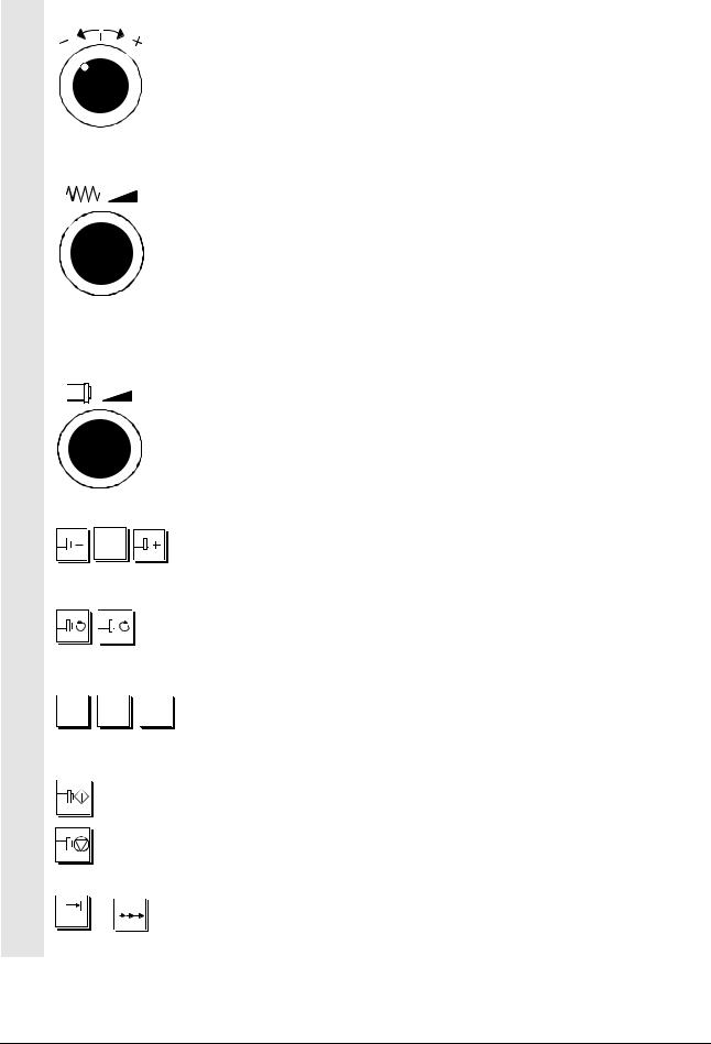
Contour handwheel
When the contour handwheel function is activated, the handwheel controls the feedrate along a programmed contour.
Feedrate override switch
The feedrate override switch can be used as required to make fine feedrate adjustments to suit the machining process.
The feed control is displayed as a percentage in the status field.
Spindle control
•Spindle speed override switch
The speed override switch is used to change the speed or peripheral speed during machining within speed limits for the selected gear step. The new value is displayed.
•Keys
100% |
The programmed spindle speed S (corresponds to 100%) can be |
|
decreased/increased with Spindle –/Spindle +. |
||
|
C + C -
[.]
or
C off
Spindle counterclockwise/clockwise rotation
These keys start the spindle in the desired direction of rotation.
Illuminated key "C axis"
This key selects the rotational direction of the C axis. The selection is disabled again by means of the traversing direction key "Off".
Illuminated keys "Spindle start" and "Spindle stop" key
This key is for starting the spindle.
This key is for stopping the spindle.
Illuminated key "Incremental dimension On/Off"
The incremental dimension display of the control system is selected/deselected with this key.
2-22 |
Siemens AG, 2002. All rights reserved |
SINUMERIK 840D/810D Operator's Guide ManualTurn (BAM) – 08.02 Edition |
2 |
|
08.02 |
Operation |
|
2 |
|
|
2.2 Machine control panel |
|
 X
X  Z
Z
K
 %
%
Illuminated keys "Handwheels X, Z On/Off"
These keys enable/disable the handwheel functions for the X and Z handwheels.
Illuminated pushbutton "Contour handwheel On/Off"
This key switches the contour handwheel on and off.
Illuminated keys "Traverse by handwheel"
The handwheel factor is set with keys 1, 10 and 100.
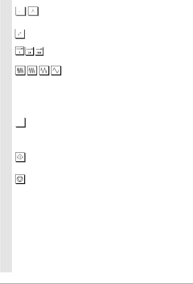
JOG keys for fixed feedrates
Fine traverse/creep feed/moderate traverse/rapid traverse button When an operating mode is active, axes are not traversed at the programmed feedrate but at a fixed feedrate setting (override has no effect).
When an operating mode has been interrupted or not started at all, these keys act as JOG keys for the feed or C axis. The travel direction is selected with the control stick or the illuminated key for the C axis.
JOG key for feedrate
When an operating mode has been interrupted or not started at all, the feed key acts as a JOG key for the feed or C axis. The override is active. The travel direction is selected with the control stick or the illuminated key for the C axis.
Illuminated key "Cycle Start/Stop"
You use the Start key to activate the function selected via the operating mode switch, e.g. single positioning step or complete machining cycle.
The Stop key can be pressed to halt a motion in progress.
The keys light up correspondingly to indicate the current operational status. The possible operational states are listed below:
•No key illuminated
The selected operating mode has not been started. You can select another operating mode or start setup.
•Start key illuminated, Stop key not illuminated
The displayed operating mode has been started. The axes move according to the way they have been selected or programmed. Setup is not possible.
•Stop key illuminated
The displayed operating mode has been started, but the motional sequence has been interrupted. Setup is possible. You can continue an interrupted movement by pressing the Start key.
Siemens AG, 2002. All rights reserved |
2-23 |
SINUMERIK 840D/810D Operator's Guide ManualTurn (BAM) – 08.02 Edition |
2 |
|
Operation |
08.02 |
|
2 |
|
2.2 Machine control panel |
|
|
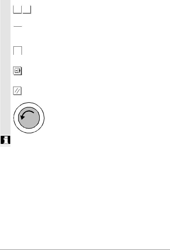
K + K -
Teach
F
Teach
RT
"Plus/Minus direction" keys
You can use these JOG keys for traversing in plus or minus direction along the contour if the contour handwheel is activated.
Key "TEACH feed"
When this key is actuated, a manually approached position is transferred to the TEACH IN memory as a feed block (G01).
Key "TEACH rapid traverse"
When this key is actuated, a manually approached position is transferred to the TEACH IN memory as a rapid traverse block (G00).
Single-step mode key
By activating the single-step mode key, you can select/deselect singlestep mode in the PROGRAM operating area.
RESET key
You can cancel a program with the RESET key.
Emergency stop key
This red key must be actuated in emergency situations, i.e.
1.when human life is at risk,
2.when there is a risk of damage to the machine or workpiece. Generally speaking, an EMERGENCY STOP command shuts down all drives with the highest possible braking torque in a controlled manner.
For further or different reactions to EMERGENCY STOP: See data supplied by machine manufacturer!
2-24 |
Siemens AG, 2002. All rights reserved |
SINUMERIK 840D/810D Operator's Guide ManualTurn (BAM) – 08.02 Edition |
2 |
|
08.02 |
Operation |
|
2 |
|
|
2.3 Mini handheld unit |
|
2.3Mini handheld unit
20 |
60 |
108 |
A
G |
F
E
H
216
D
B
|
|
|
|
|
|
|
|
|
|
|
|
|
|
|
|
|
|
|
|
|
|
|
|
|
|
|
|
|
|
|
|
|
|
|
|
|
|
|
|
|
|
|
|
|
|
|
|
|
|
|
|
|
|
|
|
|
|
|
|
|
|
|
|
|
|
|
|
|
|
|
|
|
|
|
|
|
|
|
|
|
|
|
|
|
|
|
|
|
|
|
|
|
|
|
|
|
|
|
|
|
|
|
|
|
|
|
|
|
|
|
|
|
|
|
|
|
|
|
|
|
|
|
|
|
|
|
|
|
|
|
|
|
|
|
|
|
|
|
|
|
|
|
|
|
|
|
|
|
|
|
|
|
|
|
|
|
|
|
|
|
|
|
|
|
|
|
|
|
|
|
|
|
|
|
|
|
|
|
|
|
|
|
|
|
|
|
|
|
|
|
|
|
|
|
|
|
|
|
|
|
|
|
|
|
|
|
|
|
|
|
|
|
|
|
|
|
|
|
|
|
|
|
|
|
|
|
|
|
|
|
|
|
|
|
|
|
|
|
|
|
|
|
|
|
|
|
|
|
|
|
|
|
|
|
|
|
|
|
|
|
|
|
|
|
|
|
|
|
|
|
|
|
|
|
|
|
|
|
|
|
|
|
|
|
|
|
|
|
|
|
|
|
|
|
|
|
|
|
|
|
|
I |
|
|
|
|
|
|
|
C |
|
|
|
|
|
|
|
|
|
|
|
|
|
|
|
|
|
||
88 |
|
|
|
83,5 |
|
|||||||||||||||||||||||||||||||||||||||||||||||||
|
|
|
|
|
|
|
|
|
|
|
|
|
|
|
|
|
|
|
|
|
|
|
|
|
|
|
|
|
|
|
|
|
|
|
|
|
|
|
|
|
|
|
|
|
|
|
|
|
|
|
|
|
|
|
AEMERGENCY STOP button, two-channel
BEnable key, two-channel
CAxis selection key for 5 axes and neutral position
DFunction keys F1, F2, F3
ETraversing keys direction +, –
FRapid traverse keys for fast traversal with traversing keys or handwheel
GHandwheel
HMagnetic clamps to attach to metal parts
IConnection cable 1.5m ... 3.5m
Control elements |
EMERGENCY STOP button |
The EMERGENCY STOP button must be activated in the event of an emergency
1.when human life is at risk,
2.when there is a risk of damage to the machine or workpiece.
Enable key
The enable key is designed with two positions. It must be pressed to enable triggering of traversal movements.
Siemens AG, 2002. All rights reserved |
2-25 |
SINUMERIK 840D/810D Operator's Guide ManualTurn (BAM) – 08.02 Edition |

2 |
|
Operation |
08.02 |
|
2 |
|
2.3 Mini handheld unit |
|
|
Axis selector switch
You can select up to five axes with the axis selector switch.
Function keys
You can trigger machine-specific functions with the function keys.
Traversing keys
By activating traversing keys +, – you can initiate traversal movements on the axis selected with the axis selector switch.
Handwheel
By activating the handwheel, you can initiate traversal movements on the axis selected with the axis selector switch. The handwheel returns two track signals with 100 I/rev.
Rapid traverse key
The traversing velocity of the axis selected via the axis selection key can be increased by means of the rapid traverse key. The rapid traverse key affects the travel commands of the +/– keys, as well as the handwheel signals.
2-26 |
Siemens AG, 2002. All rights reserved |
SINUMERIK 840D/810D Operator's Guide ManualTurn (BAM) – 08.02 Edition |
2 |
|
08.02 |
Operation |
|
2 |
|
|
2.4 Graphics interface |
|
2.4Graphics interface Screen layout
9
1
|
15 |
|
2 |
|
8 |
6 |
10 |
|
|
3 |
17 |
|
|
4 |
|
|
5 |
11 |
|
12 |
16 |
|
|
18 |
7 |
|
|
13 |
19 |
||
|
|||
|
|
14 |
Explanation of display |
1 |
Name of the operating modes: |
|
elements |
|
MANUAL, STRAIGHT, TAPER, CIRCLE, CYCLE, STOCK |
|
|
|
REMOVAL, CONTOUR, PROGRAM |
|
|
|
together with any applicable submenu; applies to CYCLES and |
|
|
|
CONTOUR only (e.g. Thread face, Undercut, Stock removal) |
|
|
2 |
Position displays |
|
|
3 |
Feed display |
|
|
4 |
Speed display with rotational direction |
|
|
5 |
Output display |
|
|
6 |
Tool data |
|
|
|
• |
Tool number |
|
|
• |
Tool position |
|
7 |
Status field: |
|
|
|
This field contains the following information depending on the |
|
|
|
current machining situation: |
|
|
|
• |
Test run |
|
|
• TNRC left, TNRC right (TNRC=tool nose radius compensation) |
|
|
|
• |
Dwell |
|
|
• Ack aux. command (acknowledge auxiliary command) |
|
|
|
• |
Travel command |
|
|
• Manual offs. (manual offset) |
|
|
|
• |
Current zero offset |
|
|
• Data trans. (data transmission) |
|
Siemens AG, 2002. All rights reserved |
2-27 |
SINUMERIK 840D/810D Operator's Guide ManualTurn (BAM) – 08.02 Edition |

2 |
|
Operation |
08.02 |
|
2 |
|
2.4 Graphics interface |
|
|
8Machining sequence of programmed steps
•EasyStep sequence
•Special commands (dwell time, comment, etc.)
9Current block or status line
10Graphic display area
When you press the information key, you switch between
•the EasyStep flowchart and contour display in PROGRAM operating mode
•in the other operating modes, between contour display or direction arrow and help display (if available).
11Parameter input field
12Status field for alarms and messages
13Dialog line
14Horizontal soft key menu with eight soft key functions
15Program name
16Teach-in steps displayed (e.g. Teach1, etc.)
17Cursor text display: Plaintext for the parameter underneath the cursor
18Recall: Return jump to the higher-level menu
19ETC: Extended soft key menu
2-28 |
Siemens AG, 2002. All rights reserved |
SINUMERIK 840D/810D Operator's Guide ManualTurn (BAM) – 08.02 Edition |

2 |
|
08.02 |
Operation |
|
2 |
|
|
2.5 Operating system |
|
2.5Operating system
General notes |
Options for manual intervention as well as step-by-step machining of |
|
|
lathed parts are the principle features of turning machines controlled in |
|
|
the conventional manner (X, Z; one spindle). |
|
|
With the ManualTurn system, you enter travel commands in plaintext |
|
|
via simple input screen forms in a graphics-assisted dialog. |
|
|
The following machining modes are at your disposal: |
|
|
• |
MANUAL |
|
• |
STRAIGHT |
|
• |
TAPER |
|
• |
CIRCLE |
|
• |
CYCLES |
|
• |
STOCK REMOVAL |
|
• |
CONTOUR |
|
• |
PROGRAM |
Machining possibilities With ManualTurn, workpieces can be machined as follows:
•conventionally with single-cycle machining
•automated with step chain programming using EasyStep
Single cycle machining You can parameterize the above modes (except for MANUAL and PROGRAM) as a single cycle and process them immediately with NC start, i.e. you can create a contour and then cut without having to create an entire EasyStep program.
Prerequisite for single-cycle machining is that no program is selected. An active program can be deselected by activating the "Program ON" soft key (PROGRAM mode). The "Accept" soft key is then no longer available in the single cycles.
Step chain programming with EasyStep
When generating an EasyStep program, each single cycle/individual element is created as a separate step in a machining chain (step chain) by "accepting" the parameters.
Each step is stored on one line and consists of the entered parameterization data with the associated element-specific icon. The completed machining sequence can be modified later.
Once all the machining sequence parameters have been set, the NC start key can be pressed to execute the sequence.
Under the Directory menu, PROGRAM mode offers a program management facility in which you can store the machining sequences you have created.
Siemens AG, 2002. All rights reserved |
2-29 |
SINUMERIK 840D/810D Operator's Guide ManualTurn (BAM) – 08.02 Edition |
2 |
|
Operation |
08.02 |
|
2 |
|
2.5 Operating system |
|
|
2.5.1 Operating modes
MANUAL
"Manual" mode in this case means conventional feed mode travel for longitudinal and taper turning and as well as facing. The travel direction is determined by the position of the control stick.
The reference points of the machine can also be approached in this mode.
STRAIGHT
Longitudinal turning and facing with automatic shutdown on arrival at the specified target position.
The C axis can also be traversed in this mode.
TAPER
Taper turning; the taper can be defined in three different ways.
The C axis can also be traversed in this mode.
CIRCLE
Radius machining; circular movements can be defined in three different ways.
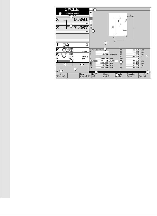
CYCLE
The CYCLE machining mode provides you with DIN-based cycles for threads, undercuts and drilling operations in the form of simple parameterization displays.
The machine manufacturer may have added other special customized cycles to this group.
The program management function allows you to store your thread and thread undercuts and call them up again whenever you need them.
STOCK REMOVAL
Stock removal mode allows machining operations based on special stock removal and grooving cycles. The machine manufacturer may also incorporate special customized cycles.
CONTOUR
In CONTOUR mode you can create and cut free contours, as well as remove residual material.
With the program management function you can store contours and call them up again whenever you need them.
2-30 |
Siemens AG, 2002. All rights reserved |
SINUMERIK 840D/810D Operator's Guide ManualTurn (BAM) – 08.02 Edition |
Loading...