


 Loading...
SINUMERIK 805
Software Version 4
PLC
Planning Guide |
11.91 |
Manufacturer Documentation
SINUMERIK 805
Software Version 4
PLC Programming
Planning Guide |
05.93 Edition |
Supplement
Order No.: 6ZB5 410-0CM02-0AN3

These sheets constitute a supplement to the edition
SINUMERIK 805
Software Version 4
PLC Programming
11.91 Edition |
Order No.: 6ZB5 410-0CM02-0AA3 |
The supplement refers to Sections 1, 3, 5, 6, 7, 8 and 9.
Please replace the following pages:
Page |
Replace |
Insert |
Delete |
|
|
|
|
|
|
Inside title page/ |
X |
|
|
|
Printing history page |
|
|
||
|
|
|
||
|
|
|
|
|
1-1 and |
1-2 |
X |
|
|
|
|
|
|
|
1-5 and |
1-6 |
X |
|
|
|
|
|
|
|
1-7 and |
1-8 |
X |
|
|
|
|
|
|
|
1-9 and 1-10 |
X |
|
|
|
|
|
|
|
|
1-11 |
|
X |
|
|
|
|
|
|
|
3-3 |
|
X |
|
|
|
|
|
|
|
3-4 to 3-8 |
|
|
X |
|
|
|
|
|
|
5-3 and |
5-4 |
X |
|
|
|
|
|
|
|
5-7 and |
5-8 |
X |
|
|
|
|
|
|
|
6-17 and |
6-18 |
X |
|
|
|
|
|
|
|
7-1 and |
7-2 |
X |
|
|
|
|
|
|
|
7-3 and |
7-4 |
X |
|
|
|
|
|
|
|
8-1 and |
8-2 |
X |
|
|
|
|
|
|
|
9-1 and |
9-2 |
X |
|
|
|
|
|
|
|
Siemens AG Automation Group
Automation Systems for Machine Tools, Robots and Special-Purpose Machines
91050 Erlangen |
Subject to change without prior |
Siemens Aktiengesellschaft |
Printed in the Fed. Rep. of Germany |
|
 Progress
 in Automation.
 Siemens

SINUMERIK 805
General Documentation
SINUMERIK |
805 |
|
|
805 |
|
Accessories |
||||||||
805 |
|
|
|
|||||||||||
|
|
|
SINUMERIK |
SINUMERIK |
SINUMERIK |
|||||||||
|
|
|
|
|
|
|||||||||
Sales Brochure |
Technical Data |
Catalog NC 34 |
Catalog NC 90 |
|||||||||||
User Documentation |
|
User/Manufacturer and Service Documentation |
||||||||||||
|
|
|
|
|
|
|
|
|
|
|
|
|
||
805 |
|
805 |
|
|
|
|
|
805 |
|
|
|
|||
|
|
|
|
|
|
|
|
|
|
|
|
|
|
|
SINUMERIK |
|
|
SINUMERIK |
|
|
|
|
|
|
SINUMERIK |
|
|
||
|
|
|
|
|
|
|
|
|
||||||
|
|
|
|
|
|
|
|
|
|
|
|
|
|
|
|
|
|
|
|
|
|
|
|
|
|
|
|
|
|
Operator©s Guide |
Programming Guide |
|
|
|
Function Manual |
|
||||||||
|
|
|
|
|
|
|
|
|
SINEC L2 Interface Module |
|
||||
|
|
|
|
|
|
|
|
|||||||
|
|
|
|
|
|
|
|
|
|
|
|
|
|
|
Manufacturer Documentation
805 |
805 |
800 |
|
|
800 |
|
|
||
805 |
|
|
|
|
|
|
|
|
|
|
|
|
|
|
|
|
|
|
|
|
|
|
|
|
|
|
|
|
|
SINUMERIK |
SINUMERIK |
|
SINUMERIK |
|
|
SINUMERIK |
|
||
SINUMERIK |
|
|
|
|
|
|
|
|
|
|
|
|
|
|
|
|
|
|
|
Instruction Manual Interface: |
PLC Programming |
Universal Interface |
CL 800 Language |
||||||
-Signals
-Cables and Connections
Service Documentation
805
SINUMERIK
Installation Guide
-Instructions
-Lists
SINUMERIK 805
Software Version 4
PLC Programming
Planning Guide
Manufacturer Documentation
05.93 Edition
SINUMERIK® documentation
Brief details of this edition and previous editions are listed below.
The status of each edition is shown by the code in the ºRemarksº column.
Status code in ºRemarksº column:
A . . . New documentation
B . . . Unrevised reprint with new Order No.
C . . . Revised edition with new status. If factual changes have been made on a page since the last edition, this is indicated by a new edition coding in the header on that page.
Edition |
Order No. |
Remarks |
01.90 |
6ZB5 410-0CM02-0BA0 |
A |
10.90 |
6ZB5 410-0CM02-0BA1 |
C |
01.91 |
6ZB5 410-0CM02-0AA2 |
C |
11.91 |
6ZB5 410-0CM02-0AA3 |
C |
05.93 |
6ZB5 410-0CM02-0AN3 |
Supplement |
Other functions not described in this documentation might be executable in the control. This does not, however, represent an obligation to supply such functions with a new control or when servicing.
This publication was produced on the Siemens 5800 Office
System.
Subject to change without prior notice.
The reproduction, transmission or use of this document or its contents is not permitted without express written authority. Offenders will be liable for damages. All rights, including rights created by patent grant or registration of a utility model or design, are reserved.
© Siemens AG 1990 All Rights Reserved
Introduction |
1 |
|||
|
|
|
|
|
Organization, Program and Sequence Blocks |
|
|||
2 |
||||
|
|
|
|
|
|
|
|
||
Data Blocks |
3 |
|||
|
|
|
||
|
|
|||
Function Blocks |
4 |
|||
|
|
|
||
|
|
|||
Program Organization |
5 |
|||
|
|
|
||
|
|
|||
Integral Function Blocks |
6 |
|||
|
|
|
||
|
|
|||
Transfer Parameters and Operating System Machine |
7 |
|||
|
|
|||
|
|
|
|
|
Error Analysis |
8 |
|||
|
|
|
||
|
|
|||
STEP 5 Command Set with Programming Examples |
9 |
|||
|
|
|
||
|
|
|||
Rules of Compatibility between LAD, CSF and STL |
10 |
|||
|
|
|
|
|
Contents
|
|
Page |
1 |
Introductory Remarks . . . . . . . . . . . . . . . . . . . . . . . . . . . . . . . . . . . |
1-1 |
1.1 |
Application, memory capacity . . . . . . . . . . . . . . . . . . . . . . . . . . . . . . |
1-1 |
1.2 |
STEP 5 programming language . . . . . . . . . . . . . . . . . . . . . . . . . . . . . |
1-2 |
1.3 |
Programming . . . . . . . . . . . . . . . . . . . . . . . . . . . . . . . . . . . . . . . . . . |
1-3 |
1.3.1 |
Program structure . . . . . . . . . . . . . . . . . . . . . . . . . . . . . . . . . . . . . . |
1-3 |
1.3.2 |
Program organization . . . . . . . . . . . . . . . . . . . . . . . . . . . . . . . . . . . . |
1-4 |
1.3.3 |
Program scanning . . . . . . . . . . . . . . . . . . . . . . . . . . . . . . . . . . . . . . |
1-5 |
1.3.4 |
Influencing factor: User program size . . . . . . . . . . . . . . . . . . . . . . . . . |
1-6 |
2 |
Organization, Program and Sequence Blocks . . . . . . . . . . . . . . . . |
2-1 |
2.1 |
Programming program blocks . . . . . . . . . . . . . . . . . . . . . . . . . . . . . . |
2-1 |
2.2 |
Calling program blocks . . . . . . . . . . . . . . . . . . . . . . . . . . . . . . . . . . . |
2-2 |
3 |
Data Blocks . . . . . . . . . . . . . . . . . . . . . . . . . . . . . . . . . . . . . . . . . |
3-1 |
3.1 |
Programming data blocks . . . . . . . . . . . . . . . . . . . . . . . . . . . . . . . . . |
3-1 |
3.2 |
Calling data blocks . . . . . . . . . . . . . . . . . . . . . . . . . . . . . . . . . . . . . . |
3-2 |
3.3 |
Data blocks created by the operating system . . . . . . . . . . . . . . . . . . . |
3-4 |
4 |
Function Blocks . . . . . . . . . . . . . . . . . . . . . . . . . . . . . . . . . . . . . . |
4-1 |
4.1 |
General remarks . . . . . . . . . . . . . . . . . . . . . . . . . . . . . . . . . . . . . . . |
4-1 |
4.2 |
Structure of function blocks . . . . . . . . . . . . . . . . . . . . . . . . . . . . . . . . |
4-2 |
4.2.1 |
Block header . . . . . . . . . . . . . . . . . . . . . . . . . . . . . . . . . . . . . . . . . . |
4-2 |
4.2.2 |
Block body . . . . . . . . . . . . . . . . . . . . . . . . . . . . . . . . . . . . . . . . . . . |
4-2 |
4.3 |
Calling and initializing function blocks . . . . . . . . . . . . . . . . . . . . . . . . . |
4-3 |
4.3.1 |
Call statement . . . . . . . . . . . . . . . . . . . . . . . . . . . . . . . . . . . . . . . . . |
4-3 |
4.3.2 |
Parameter list . . . . . . . . . . . . . . . . . . . . . . . . . . . . . . . . . . . . . . . . . . |
4-3 |
4.4 |
Programming function blocks . . . . . . . . . . . . . . . . . . . . . . . . . . . . . . . |
4-4 |
4.4.1 |
Library number . . . . . . . . . . . . . . . . . . . . . . . . . . . . . . . . . . . . . . . . . |
4-4 |
4.4.2 |
Name of the function block . . . . . . . . . . . . . . . . . . . . . . . . . . . . . . . . |
4-4 |
4.4.3 |
Formal operand (block parameter name) . . . . . . . . . . . . . . . . . . . . . . . |
4-5 |
4.4.4 |
Block parameter types . . . . . . . . . . . . . . . . . . . . . . . . . . . . . . . . . . . |
4-6 |
4.4.5 |
Block parameters and permitted actual parameters . . . . . . . . . . . . . . . |
4-7 |
5 |
Program Organization . . . . . . . . . . . . . . . . . . . . . . . . . . . . . . . . . . |
5-1 |
5.1 |
General remarks . . . . . . . . . . . . . . . . . . . . . . . . . . . . . . . . . . . . . . . |
5-1 |
5.2 |
Cyclic scanning . . . . . . . . . . . . . . . . . . . . . . . . . . . . . . . . . . . . . . . . |
5-2 |
5.2.1 |
Interrupt capability . . . . . . . . . . . . . . . . . . . . . . . . . . . . . . . . . . . . . . |
5-2 |
5.2.2 |
Response time and cycle time . . . . . . . . . . . . . . . . . . . . . . . . . . . . . . |
5-3 |
5.2.3 |
Programming the cyclic program . . . . . . . . . . . . . . . . . . . . . . . . . . . . |
5-3 |
5.2.4 |
Interface between operating system and cyclic program . . . . . . . . . . . . |
5-4 |
5.2.5 |
Basic program organization . . . . . . . . . . . . . . . . . . . . . . . . . . . . . . . . |
5-5 |
5.3 |
Interrupt processing . . . . . . . . . . . . . . . . . . . . . . . . . . . . . . . . . . . . . |
5-7 |
5.3.1 |
Programming the interrupt service routine . . . . . . . . . . . . . . . . . . . . . . |
5-7 |
5.3.2 |
Interface between operating system and the interrupt . . . . . . . . . . . . . . |
5-7 |
5.3.3 |
Response time . . . . . . . . . . . . . . . . . . . . . . . . . . . . . . . . . . . . . . . . . |
5-8 |
6 |
Integral Function Blocks . . . . . . . . . . . . . . . . . . . . . . . . . . . . . . . . |
6-1 |
||
6.1 |
General remarks . . . . |
. . . . . . . . . . . . . . . . . . . . . . . . . . . . . . . . . . . . |
6-1 |
|
6.2 |
FB identifiers . . . . . . |
. . . . . . . . . . . . . . . . . . . . . . . . . . . . . . . . . . . . |
6-2 |
|
6.3 |
Function macros . . . . |
. . . . . . . . . . . . . . . . . . . . . . . . . . . . . . . . . . . . |
6-3 |
|
|
FB 11 |
EINR-DB |
Generate data blocks . . . . . . . . . . . . . . . . . . . . |
6-4 |
|
FB 60 |
BLOCK-TR |
Block transfer . . . . . . . . . . . . . . . . . . . . . . . . . |
6-6 |
|
FB 61 |
NCD-LESE |
Read NC data |
|
|
FB 62 |
NCD-SCHR |
Write NC data . . . . . . . . . . . . . . . . . . . . . . . . . |
6-8 |
|
FB 65 |
M STACK |
Transfer flags to stack . . . . . . . . . . . . . . . . . . . |
6-18 |
|
FB 66 |
STACK M |
Flag stack to transfer flag area . . . . . . . . . . . . . |
6-18 |
7 |
Transfer Parameters and Operating System Machine Data . . . . . . |
7-1 |
||
7.1 |
Transfer parameters . |
. . . . . . . . . . . . . . . . . . . . . . . . . . . . . . . . . . . . |
7-1 |
|
7.2 |
PLC machine data SINUMERIK 805 . . . . . . . . . . . . . . . . . . . . . . . . . . |
7-4 |
||
7.3 |
PLC machine data bits SINUMERIK 805 . . . . . . . . . . . . . . . . . . . . . . . |
7-5 |
||
8 |
Error Analysis . . . . . |
. . . . . . . . . . . . . . . . . . . . . . . . . . . . . . . . . . . . |
8-1 |
|
8.1 |
Types of error . . . . . |
. . . . . . . . . . . . . . . . . . . . . . . . . . . . . . . . . . . . |
8-1 |
|
8.2 |
Interrupt stack . . . . . |
. . . . . . . . . . . . . . . . . . . . . . . . . . . . . . . . . . . . |
8-3 |
|
8.3 |
Detailed error code . . |
. . . . . . . . . . . . . . . . . . . . . . . . . . . . . . . . . . . . |
8-5 |
|
8.3.1 |
Display on programmer . . . . . . . . . . . . . . . . . . . . . . . . . . . . . . . . . . . |
8-5 |
||
8.3.2 |
Display on NC screen |
. . . . . . . . . . . . . . . . . . . . . . . . . . . . . . . . . . . . |
8-6 |
|
8.4 |
Alarm List . . . . . . . . . |
. . . . . . . . . . . . . . . . . . . . . . . . . . . . . . . . . . . |
8-7 |
|
9 |
STEP 5 Command Set with Programming Examples . . . . . . . . . . . . |
9-1 |
||
9.1 |
Memory organization . |
. . . . . . . . . . . . . . . . . . . . . . . . . . . . . . . . . . . . |
9-1 |
|
9.1.1 |
Changing the segment switch . . . . . . . . . . . . . . . . . . . . . . . . . . . . . . |
9-3 |
||
9.1.2 |
Block lists . . . . . . . . . |
. . . . . . . . . . . . . . . . . . . . . . . . . . . . . . . . . . . |
9-3 |
|
9.2 |
General notes . . . . . |
. . . . . . . . . . . . . . . . . . . . . . . . . . . . . . . . . . . . |
9-6 |
|
9.2.1 |
Numeric representation . . . . . . . . . . . . . . . . . . . . . . . . . . . . . . . . . . . |
9-6 |
||
9.2.2 |
Condition codes of the PLC . . . . . . . . . . . . . . . . . . . . . . . . . . . . . . . . |
9-8 |
||
9.2.3 |
STEP 5 command representation . . . . . . . . . . . . . . . . . . . . . . . . . . . . |
9-9 |
||
9.3 |
Basic operations . . . . |
. . . . . . . . . . . . . . . . . . . . . . . . . . . . . . . . . . . . |
9-11 |
|
9.3.1 |
Logic operations, binary . . . . . . . . . . . . . . . . . . . . . . . . . . . . . . . . . . |
9-11 |
||
9.3.2 |
Storage operations . . |
. . . . . . . . . . . . . . . . . . . . . . . . . . . . . . . . . . . . |
9-14 |
|
9.3.3 |
Load and transfer operations . . . . . . . . . . . . . . . . . . . . . . . . . . . . . . . |
9-17 |
||
9.3.4 |
Timing and counting operations . . . . . . . . . . . . . . . . . . . . . . . . . . . . . |
9-19 |
||
9.3.5 |
Comparison operations . . . . . . . . . . . . . . . . . . . . . . . . . . . . . . . . . . . |
9-27 |
||
9.3.6 |
Block calls . . . . . . . . . |
. . . . . . . . . . . . . . . . . . . . . . . . . . . . . . . . . . . |
9-31 |
|
9.3.7 |
Code operations . . . . |
. . . . . . . . . . . . . . . . . . . . . . . . . . . . . . . . . . . . |
9-33 |
|
9.3.8 |
Arithmetic operations |
. . . . . . . . . . . . . . . . . . . . . . . . . . . . . . . . . . . . |
9-34 |
|
9.3.9 |
Other operations . . . . |
. . . . . . . . . . . . . . . . . . . . . . . . . . . . . . . . . . . . |
9-35 |
|
9.4 |
Supplementary operations (with function blocks only) . . . . . . . . . . . . . . |
9-34 |
||
9.4.1 |
Logic operations, binary . . . . . . . . . . . . . . . . . . . . . . . . . . . . . . . . . . |
9-35 |
||
9.4.2 |
Setting operations . . . |
. . . . . . . . . . . . . . . . . . . . . . . . . . . . . . . . . . . . |
9-35 |
|
9.4.3 |
Timing and counting operations . . . . . . . . . . . . . . . . . . . . . . . . . . . . . |
9-36 |
||
9.4.4 |
Enabling operations for timing and counting operations . . . . . . . . . . . . . |
9-38 |
||
9.4.5 |
Bit test operations (with function blocks only) . . . . . . . . . . . . . . . . . . . |
9-39 |
9.4.6 |
Coding, load and transfer operations . . . . . . . . . . . . . . . . . . . . . . . . . |
9-40 |
9.4.7 |
Logic operations, digital . . . . . . . . . . . . . . . . . . . . . . . . . . . . . . . . . . |
9-41 |
9.4.8 |
Shift operations . . . . . . . . . . . . . . . . . . . . . . . . . . . . . . . . . . . . . . . . |
9-41 |
9.4.9 |
Conversion operations . . . . . . . . . . . . . . . . . . . . . . . . . . . . . . . . . . . |
9-42 |
9.4.10 |
Decrementing / Incrementing . . . . . . . . . . . . . . . . . . . . . . . . . . . . . . . |
9-42 |
9.4.11 |
Jump operations . . . . . . . . . . . . . . . . . . . . . . . . . . . . . . . . . . . . . . . |
9-43 |
9.4.12 |
Processing operations . . . . . . . . . . . . . . . . . . . . . . . . . . . . . . . . . . . . |
9-46 |
9.4.13 |
STEP 5 commands with direct memory access . . . . . . . . . . . . . . . . . . |
9-48 |
9.4.14 |
Other operations . . . . . . . . . . . . . . . . . . . . . . . . . . . . . . . . . . . . . . . |
9-49 |
9.5 |
Command Set with Programming Examples . . . . . . . . . . . . . . . . . . . . |
9-50 |
10 |
Rules of Compatibility between the LAD, CSF and |
|
|
STL Methods of Representation . . . . . . . . . . . . . . . . . . . . . . . . . . . |
10-1 |
10.1 |
General . . . . . . . . . . . . . . . . . . . . . . . . . . . . . . . . . . . . . . . . . . . . . . |
10-1 |
10.2Rules of compatibility for graphic program input
|
(LAD, CSF) . . . . . . . . . . . . . . . . . . . . . . . . . . . . . . . . . . . . . . . . . . . |
10-2 |
10.3 |
Rules of compatibility for program input in a statement list . . . . . . . . . . |
10-4 |
Preliminary
Notes for the reader
This manual is intended for the manufacturers of machine tools using SINUMERIK 805.
The Guide describes the program structure and the operation set of the PLC, and explains how basic PLC software and user programs, which comprise data blocks, function blocks, program blocks and organization blocks, are constructed.
The SINUMERIK documentation is organized in three levels:
·User documentation
·Manufacturer documentation and
·Service documentation
The Manufacturer Documentation for SINUMERIK 805 is divided into the following:
·Instruction Manual
·Description of interfaces Part 1: Signals
Part 2: Cables and hardware
·PLC Programming
Additional SINUMERIK publications are also available for all SINUMERIK controls (e. g. publications on the Universal Interface, Measuring Cycles, CL 800 Cycles language).
Please contact your Siemens regional office for further details.
Technical
This documentation applies to software version 4
05.93 |
1 Introductory Remarks |
1.1 Application, memory capacity
1 Introductory Remarks
1.1Application, memory capacity
The PLC is a powerful interface controller. It has no inherent hardware, and is used as ºsoftware PLCº in the SINUMERIK 805.
The PLC is responsible for control of machine-related functional sequences such as
·Controlling auxiliary axes
·Controlling tool-changers
·Gathering the signals generated by the machine©s monitoring devices.
Special features:
On the SINUMERIK 805, all NC and PLC jobs are executed by a common processor
(Intel 80 186). A specially developed coprocessor (COP) is responsible for high-speed execution of binary operations and byte and word commands of the STEP 5 user program (e. g.
A I 3.0, L FW3, etc.).
The single-processor structure calls for strict priority scheduling of NC and PLC jobs. NC functions such as position control and block preparation, but also the PLC ºInterrupt processingº function (OB 2), have highest priority, while scanning of the cyclic program (OB 1) is of lesser importance.
The amount of processor time available to the PLC has been restricted to a maximum of 20% in order to ensure that the NC can fulfill its primary objectives (positioning accuracy, short block change times) even in extreme situations, e. g. where an exceptionally long STEP 5 program or frequent interrupt servicing is involved. It is also possible to influence the manner in which the cyclic user program scanned via machine data (see Section 1.3.4).
PLC memory capacity of the SINUMERIK 805
User memory (OB, PB, FB, SB): |
8 Kbytes |
|
|
16 Kbytes (from SW 4.1, Basic Version) |
|
|
32 Kbytes (from SW 4.1, in Option N46) |
|
Data memory (DB): |
4 |
Kbytes |
|
6 |
Kbytes (from SW 4.1, Basic Version) |
|
8 |
Kbytes (from SW 4.1, in Option N46) |
© Siemens AG 1990 All Rights Reserved 6ZB5 410-0CM02 |
1±1 |
SINUMERIK 805 (PJ)

1 Introductory Remarks |
11.91 |
1.2 STEP 5 programming language
1.2STEP 5 programming language
The operations available in STEP 5 enable the user to program functions ranging from simple binary logic to complex digital functions and basic arithmetic operations.
Depending on the programmer (PG) used a STEP 5 program may be written in the form of a control system flowchart (CSF), ladder diagram (LAD) or statement list (STL) , thus enabling the programming method to be adapted to the application. The machine code (MC5) generated by the programmers is identical for all three. Depending on the programmer (PG) used, the user program can be translated from one method of representation to another by conforming to certain programming conventions (see Section10).
Ladder diagram |
Statement list |
Control system |
|
|
flowchart |
|
|
|
Programming with |
Programming with |
Programming |
symbols similar to |
using mnemonics |
with graphic |
those used in sche- |
designating |
symbols |
matic circuit dia- |
functions |
|
grams |
|
|
Complies with |
Complies with |
Complies with |
DIN 19239 |
DIN 19239 |
IEC 117 - 15 |
(draft) |
(draft) |
DIN 40700 |
|
|
DIN 40719 |
|
|
DIN 19239 |
|
|
(draft) |
LAD |
|
STL |
|
CSF |
|
|
A |
I |
& |
|
( ) |
AN |
I |
|
|
|
|||
|
A |
I |
>=1 |
|
|
|
|||
|
|
ON |
I |
|
|
|
|
||
|
|
O |
I |
|
|
|
= |
Q |
|
Methods of representing the STEP 5 programming language
1-2 |
© Siemens AG 1990 All Rights Reserved 6ZB5 410-0CM02 |
SINUMERIK 805 (PJ)
10.90 |
1 Introductory Remarks |
1.3 Programming
1.3Programming
1.3.1Program structure
The PLC software comprises the operating system, the basic software and the user program. The operating system contains all statements and declarations for internal system functions. The basic software has a flexible interface to the operating basic functions (e. g. generation of data blocks, NC-PLC interface initialization, signal interchange with the peripherals). The basic software also contains pretested function blocks written in STEP 5 and assembled to form function macros.
The operating system and the basic software are integral components of the PLC; they are supplied on EPROMs together with the NC system program, and may not be modified in any way.
The user program is the total of all statements and declarations/data programmed by the user.
The PLC structure makes structured programming essential, i. e. the program must be divided into individual, self-contained sections called blocks. This method offers the following advantages:
·Easy, lucid programming, even of large programs
·Easy standardization of program sections
·Simple program organization
·Fast, easy modification
·Simple program testing
·Easy start-up
A number of block types, each of which is used for different tasks, is available for structuring the user program:
·Organization blocks (OBs)
The OBs serve as interface between operating system and user program.
·Program blocks (PBs)
The PBs are used to break the user program down into technologically oriented sections.
·Function blocks (FBs)
The FBs are used to program frequently recurring complex functions (such as individual controls, reporting, arithmetic and PID control functions).
·Sequence blocks (SBs)
SBs are special forms of program blocks used primarily for processing sequencers.
·Data blocks (DBs)
DBs are used for storing data or texts, and differ in both function and structure from all other block types.
With the exception of the organization blocks, the maximum number of programmable blocks of each type is 255. The number of organization blocks may not exceed 64; of these, only OB 20, PB 1 and OB 2 are serviced by the operating system (cf. Section 5).
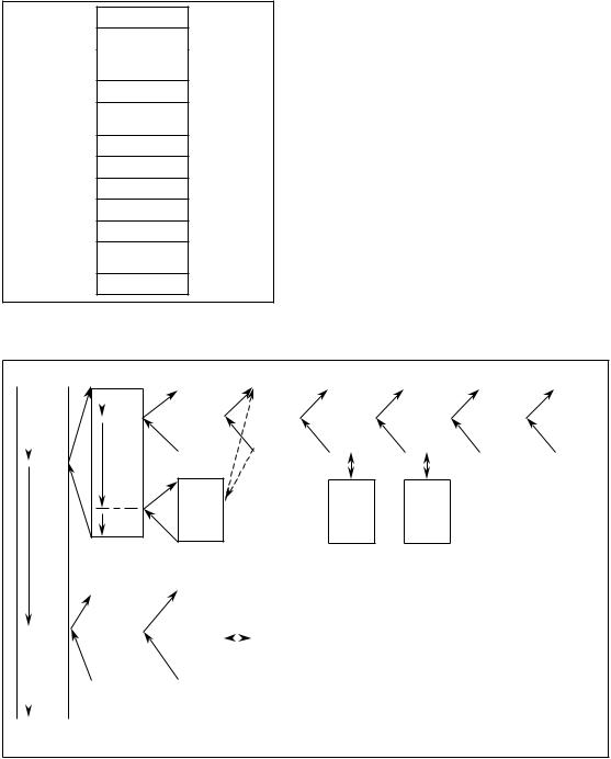
The programmer stores all programmed blocks in arbitrary order in program memory (Fig. 1.2).
© Siemens AG 1990 All Rights Reserved 6ZB5 410-0CM02 |
1-3 |
SINUMERIK 805 (PJ)
1 Introductory Remarks |
10.90 |
1.3.2 Program organization
1.3.2Program organization
The manner in which the program is organized determines whether and in what order the program, function and sequence blocks are executed. The order in which these blocks are involved is stipulated by programming the relevant calls (conditional or unconditional) in organization blocks (see Section 5.4, ºCyclic programº).
Like the other blocks, the organization blocks are stored in user memory.
PB1
PB2
·
·
FB1
·
·
DB1
·
SB10
·
FX1
·
·
OB1
Different organization blocks are provided for various methods of program execution (cf. Section 5.2).
Organization, program, function and sequence blocks can invoke other program, function and sequence blocks. The user program cannot call organization blocks. The maximum permissible nesting depth for organization blocks is 12, not including an accompanying data block, if any.
Storing the blocks in arbitrary order in program memory
OB |
|
|
|
|
|
PB |
|
|
|
|
|
|
FB |
|
|
|
FB |
|
PB |
PB |
FB |
FB |
||||||||
|
|
|
|
|
|
|
|
|
|
|
|
|
|
|
|
|
|
|
|
|
|
|
|
|
|
|
|
|
|
|
|
|
|
|
|
|
|
|
|
|
|
|
|
|
|
|
|
|
|
|
|
|
|
|
|
|
|
|
|
|
|
|
|
|
|
|
|
|
|
|
|
|
|
|
|
|
|
|
|
|
|
|
|
|
|
|
|
|
|
|
|
|
|
|
|
|
|
|
|
|
|
|
|
|
|
|
|
|
|
|
|
|
|
|
|
|
|
|
|
|
|
|
|
PB |
DB |
DB |
|
|
|
|
|
|
|
|
|
PB |
|
|
FB |
|
|
|
|
|
DB |
|
|
|
|
|
|
|
|
||||||
|
|
|
|
|
|
|
|
|
|
|
|
|
|
|
|
|
|
|
|
|
|
|
|
|
|
|
|
|
|
|
|
|
|
|
|
|
|
|
|
|
|
|
|
|
|
|
|
|
|
|
|
|
|
|
|
|
|
|
|
|
|
OB |
Organization block |
|
|
|
|
|
|
|
|
|
|
|
|
|
|
|
|
|
|
|
|
|
|
|
|
|
|
|
|
|
|
|
PB |
Program block |
|
|
|
|
|
|
|
|
|
|
|
|
|
|
|
|
|
|
|
|
|
|
|
|
|
|
|
|
|
|
|
|
|||
|
|
|
|
|
|
|
|
|
|
|
|
|
|
|
|
|
|
|
|
|
|
|
|
|
|
|
|
|
|
|||
|
|
|
|
|
|
|
|
|
|
|
|
|
|
|
|
|
|
|
|
|
|
|
|
|
|
|
|
|
FB |
Function block |
|
|
|
|
|
|
|
|
|
|
|
|
|
|
|
|
|
|
|
|
|
|
|
|
|
|
|
|
|
|
|
DB |
Data block |
|
|
|
|
|
|
|
|
|
|
|
|
|
|
|
|
|
|
|
|
|
|
|
|
|
|
|
|
|
|
|
|
|||
|
|
|
|
|
|
|
|
|
|
|
|
|
|
|
|
|
|
|
|
|
|
|
|
|
|
|
||||||
|
|
|
|
|
|
|
|
|
|
|
|
|
|
|
|
|
|
|
|
|
|
|
|
|
|
|
||||||
|
|
|
|
|
|
|
|
|
|
|
|
|
|
|
|
|
|
|
|
|
|
|
|
|
|
|
|
|
|
|
|
|
|
|
|
|
1 |
|
|
|
|
|
2 |
|
|
3 |
|
|
|
4 |
|
|
|
5 |
|
|
6 |
7 |
8 |
||||||
|
|
|
|
|
|
|
|
|
|
|
|
|
|
|
|
|
|
|
|
|
|
|
|
|
|
|
|
|
|
|
|
|
Typical program organization in STEP 5 (nesting depth 8) (max. nesting depth 12)
1-4 |
© Siemens AG 1990 All Rights Reserved 6ZB5 410-0CM02 |
|
SINUMERIK 805 (PJ) |
05.93 |
1 Introductory Remarks |
1.3.3 Program scanning
1.3.3Program scanning
The user program can be scanned in three ways:
·One-shot scan
One-shot scan in the controller©s restart routine following ºPower upº or ºHardware resetº. The statements to be executed must be programmed in OB 20.
·Cyclic scanning
For cyclic scanning 0B1 is available. This block is passed at intervals of 48 ms (up to SW4.1: 60 ms) and calls the programmed blocks.
·Interrupt scan
Event-driven, one-shot execution of the statements in OB 2, e. g. in response to an interrupt. Prerequisites for event-driven execution are as follows:
·Normal termination of the controller©s restart routine
·Interrupt enable via PLC-MD 2002, bit 0=º0º.
·A change in the interrupt input byte specified per PLC-MD 0.
Cyclic scanning can be interrupted by the high-priority NC functions© interrupt service routine or delayed pending termination of OB 2 following execution of each STEP 5 command.
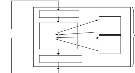
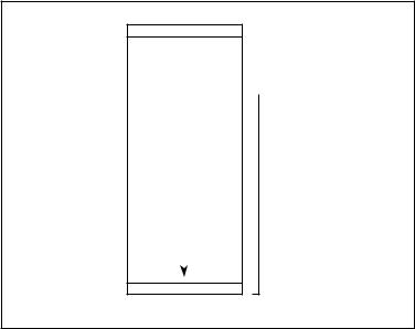
Execution of a PLC cycle; cyclic program scanning
Before OB 1 is called and started, the basic program loads the momentary state of all peripheral inputs into working memory. All input scans in the cycle which follows refer to this loaded status image. It is also known as ºProcess Input Imageº or PII for short.
OB 1 is now called. This executes the blocks that have been called one after the other. This process can be interrupted by one or several interrupt scans (OB 2).
When OB 1 has been worked through completely, the system program transferss the statuses of the outputs (resulting from program execution) from the working memory to the peripheral outputs (MDP submodules, for example).
|
Load Process Input Image |
|
|
|
|
PB 1 |
|
|
OB 1 scan |
A I 3.1 |
|
|
= Q 2.0 |
||
|
OB 1 |
||
48 (60 )ms |
BE |
||
SPA PB 1 |
|||
time base |
PLC cycle |
||
SPA FB 1 |
FB 1 |
||
|
|||
|
BE |
A F 0.1 |
|
|
= Q 3.6 |
||
|
|
BE |
|
|
Write Process Output Image |
|
© Siemens AG 1990 All Rights Reserved 6ZB5 410-0CM02 |
1±5 |
SINUMERIK 805 (PJ)
1 Introductory Remarks |
05.93 |
1.3.4 Influencing factor: User program size
1.3.4Influencing factor: User program size
As mentioned in Section 1.1, execution of the STEP 5 program should not take up more then 15 % of the total available CPU time, nor should the interrupt service routine in OB 2 take up more time than necessary because of its high priority, as this would delay execution of important NC functions.
For this purpose, the execution times of both the cyclic user program and the interrupt service routine are monitored at the hardware level. The permissible runtimes can be set in PLC MD 1 and 3, whereby confirmation of the defaults ensures that the ºintegrated PLCº will not take up more than the admissible amount of CPU time. When these values are exceeded, the PLC goes to the state specified in bit 0 or 1 of PLC MD 2003; when the defaults are used, the ºintegrated PLCº always enters the Stop mode.
When the user programs exceed the permissible execution times only slightly, program scanning can be upheld by modifying these machine data bits, but this may adversely affect the NC functions.
There are two ways of ensuring the executability of large cyclic user programs without placing an excessive load on the CPU:
·Fragmenting cyclic execution through autonomous interrupts
·Allowing cyclic execution to be interrupted by higher-priority program blocks only
The mode is set in PLC MD 2003, bit 6. The percentage in PLC MD thus assumes the following meaning as regards the scan time:
·No fragmenting (bit 6 of MD 2003 = 0 =Ã default):
15% of the cyclic program©s timing grid (48 ms) results in a permissible runtime of 7.2 ms.
·Fragmenting (bit 6 of MD 2003 = 1)
15% of 1/3 of the cyclic program©s timing grid (48 ms) results in a runtime of 2.4 ms. The cyclic program then interrupts itself autonomously, and resumes execution in the next third.
1±6 |
© Siemens AG 1990 All Rights Reserved 6ZB5 410-0CM02 |
SINUMERIK 805 (PJ)
05.93 |
1 Introductory Remarks |
1.3.4 Influencing factor: User program size
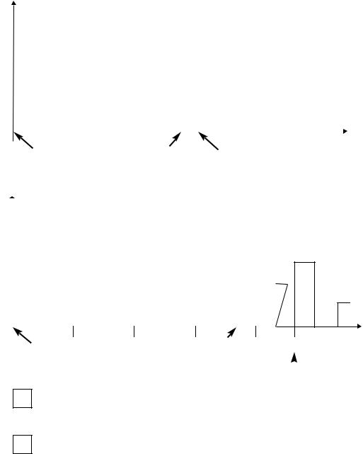
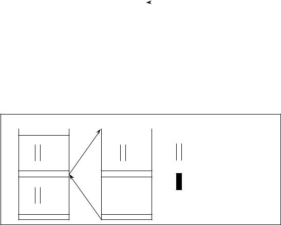
Grafic overview of the two methods for cyclic program scanning
Note: OB 1 (cyclical user program) can only be called up in the 48 ms grid (up to SW 4.1: 60 ms).
Priority |
|
No fragmenting |
PLC program is executed within the 60 ms grid. |
|||||||||
|
|
|
|
|
|
|
|
|
|
|
|
|
|
|
|
|
|
|
|
|
|
|
|
|
|
|
|
|
|
|
|
|
|
|
|
|
|
|
|
|
|
|
|
|
|
|
|
|
|
|
|
|
|
|
|
|
|
|
|
|
|
|
|
|
|
|
|
|
|
16 (20) |
|
32 (40) |
|
OB 1 |
|
48 (60) |
The PLC operating |
t/ms |
||||||||
|
|
|
|
|
|||||||||||||||||
|
|
|
|
OB 1 |
|
|
|
|
|
|
|
|
|
||||||||
|
|
|
|
|
|
|
|
|
|
|
|
|
|
||||||||
|
|
|
|
call |
|
|
|
|
|
|
|
end |
|
|
|
|
|||||
|
|
|
|
|
|
|
|
|
|
|
|
|
system (OB 1) |
|
|||||||
|
|
|
|
|
|
|
|
|
|
|
|
|
|
|
|
|
|
||||
|
|
|
|
|
|
|
|
|
|
|
|
|
|
|
|
|
|
||||
|
|
|
|
|
|
|
|
|
|
|
|
|
|
|
|
|
recalls the cyclic user program |
|
|||
|
|
|
|
|
|
|
|
|
|||||||||||||
Priority |
|
Fragmenting |
PLC program could not be executed within the 48 ms (60 ms) time |
||||||||||||||||||
|
|||||||||||||||||||||
|
|
|
|
|
|
|
|
base and therefore ºFragmentingº had to be selected. |
|
||||||||||||
|
|
|
|
|
|
|
|
|
|||||||||||||
|
|
|
|
|
|
|
|
|
|
|
|
|
|
|
|
|
|
|
|
|
|
|
|
|
|
|
|
|
|
|
|
|
|
|
|
|
|
|
|
|
|
|
|
|
|
|
|
|
|
|
|
|
|
|
|
|
|
|
|
|
|
|
|
|
|
|
|
|
|
|
|
|
|
|
|
|
|
|
|
|
|
|
|
|
|
|
|
0 |
16 (20) |
32 (40) |
48 (60) |
OB 1 call
Higher-priority NC and PLC program blocks
Cyclic user program scanning (OB 1)
Low-priority NC program blocks
|
|
64 (80) |
96 (120) |
t/ms |
|
OB 1 |
|
||||
end |
|
|
|
|
|
|
|
|
|
||
|
|
|
|
|
|
|
|
|
|
|
|
OB 1 call
If the OB 1 (cyclical useer program) is too large to be processed in the 48 ms (up to SW 4.1: 60 ms) grid, fragmentation must be selected.
© Siemens AG 1990 All Rights Reserved 6ZB5 410-0CM02 |
1±7 |
SINUMERIK 805 (PJ)
1 Introductory Remarks |
05.93 |
1.3.4 Influencing factor: User program size
The timing grid,of cyclic program scanning is 12 x the scanning time of the position control (12 x 4 ms = 48 ms; up to SW 4.1: 12 x 5 = 60 ms).
The admissible execution time of the cyclic program for both variants can also be increased by augmenting PLC MD 1 (CPU load in %).
The admissible runtime for the interrupt service routine (PLC MD 3), regardless of the cyclic execution mode, may not exceed 2000 us in an interval of 4 * scanning time (4 x 4 ms =
16 ms; up to SW 4.1: 4 x 5 = 20 ms).
The entire runtime may either be used for one-shot execution of the statements in OB 2 or, in an extreme situation, for 4-shot execution of OB 2, as the interrupt input byte is scanned for an edge change on the basis of the scanning time. If the default runtime for OB 2 proves insufficient, PLC-MD 3 must either be incremented (to max. 2500 µs) or the PLC set to the Stop mode when OB 2 exceeds the allotted time by modifying bit 1 in PLC MD 2003. The example on the next page emphasizes the difference between the two variants for a cyclic user program with a runtime time of 25 ms.
No fragmentation:
The cyclic user program may be interrupted by higher-priority NC and PLC program blocks only ( e. g. position control, interpolation, monitoring functions, programming and test functions, interrupt service routine (OB 2)). It is otherwise continued until it has terminated and all signals it generated habe been forwarded to their destinations (NC, I/Os). Only then can the low-priority functions execute.
Depending on the size of the STEP 5 program in OB 1, the remaining interval may be quite shorte, as the operating system recalls the cyclic program when 48 ms (up to SW 4.1: 60 ms) have passed. The consequence is that too little time is available for the low-priority functions, a fact which becomes immediately apparent in a sluggish ºoperator interfaceº. Display construction is extremely slow, as is the controller©s reaction to keyboard entries. In extreme situations, the low-priority functions are allatted almost no time at all to execute.
In the example, (runtime of cyclic user program = 25 ms, SW 4.2 installed) the CPU load caused by the STEP 5 program alone would escalate to value x, where
x = |
25 ms . |
100 % = |
52 % , assuming that cyclic execution |
|
48 ms |
||||
|
|
|
is terminated within 48 ms. In the example, no regard was paid to the 5% basic load resulting from data transfers prior to and following the OB 1 call.
It is obvious that a CPU load of almost 57% for the controller alone is not acceptable.
1±8 |
© Siemens AG 1990 All Rights Reserved 6ZB5 410-0CM02 |
SINUMERIK 805 (PJ)
05.93 |
1 Introductory Remarks |
1.3.4 Influencing factor: User program size
Fragmenting:
When this variant is used, the cyclic program interrupts itself autonomously. If the default is used (values for SW 4.2), the CPU load, referred to the cyclic program timing grid, would be:
x = |
2.4 ms . |
3 . 100 %=15 % |
|
||
|
48 ms |
|
The basic load for the cyclic program, about 5%, must be added to this, so that the cyclic program load on the CPU would always be 20 %. It is less than 20% when cyclic execution is not terminated within one timing period. Extremely long cyclic user programs may cause the cycle time monitor to response (default: 300 ms).
Note:
By selecting the diagnostics function (PLC MD 2003, bit 7 = 1), the user can obtain a general view of the anticipated run time for STEP 5 programs as well as the required cycle time. On the basis of these data, he can optimize the configuration of his MD as regards his job requests and the purpose for which the controller is to be used (cf. section 8 ºError Analysisº).
© Siemens AG 1990 All Rights Reserved 6ZB5 410-0CM02 |
1±9 |
SINUMERIK 805 (PJ)
1 Introductory Remarks |
11.91 |
1.4 Block overview
1.4Block overview
Organization data blocks
OB No. |
OB designation |
OB name |
|
|
|
|
|
|
|
1 |
|
OB for cyclic scanning |
|
|
|
User |
|
||
2 |
|
OB for interrupt scanning |
|
|
|
assignable |
|
||
20 |
|
OB for one-shot scan after starting |
|
|
|
|
|
||
|
|
|
|
|
Program data blocks
PB No. |
PB designation PB name |
0
User assignable
255
Function data blocks
FB No. |
FB designation |
PB name |
|
|
|
0 |
|
Reserved |
10 |
|
Reserved |
11 |
EINR-DB |
Generate data blocks |
12 |
|
Reserved |
59 |
|
Reserved |
60 |
BLOCK-TR |
Blocktransfer |
61 |
NCD-LESE |
Read NC data |
62 |
NCD-SCHR |
Write NC data |
63 |
|
Reserved |
64 |
|
Reserved |
65 |
M-STACK |
Transfer flags to stack |
66 |
STACK-M |
Flag stack to transfer flag area |
70 |
|
Reserved |
104 |
SEND |
|
105 |
RECEIVE |
SINEC L2 |
106 |
CONTROL |
|
199 |
|
Reserved |
200 |
|
User assignable |
255 |
|
User assignable |
|
|
|
1±10 |
© Siemens AG 1990 All Rights Reserved 6ZB5 410-0CM02 |
SINUMERIK 805 (PJ)

05.93 |
1 Introductory Remarks |
|
1.4 Block overview |
Data blocks
DB No. |
DB designation |
DB name |
|
|
|
0 |
|
Address list block |
1 |
|
Diagnostics DB |
2 |
|
Reserved |
27 |
|
Reserved |
28 |
|
Interface for analog output (from SW 4.2) |
29 |
|
Reserved |
35 |
|
Reserved |
36 |
|
Interface for data transfer |
37 |
|
Interface for serial interface control |
38 |
|
Reserved |
70 |
|
Reserved |
71 |
|
User assignable |
255 |
|
User assignable |
|
|
|
Sequence blocks
SB No. |
SB designation SB name |
0
User assignable
255
© Siemens AG 1990 All Rights Reserved 6ZB5 410-0CM02 |
1±11 |
SINUMERIK 805 (PJ)

01.91 |
2 Organization, Program and Sequence Blocks |
2.1 Programming program blocks
2 Organization, Program and Sequence Blocks
2.1Programming program blocks
The information presented in this Section applies to the programming of organization (OBs), program (PBs) and sequence blocks (SBs). These three block types are all programmed in the same way. Section 3 gives information on programming data blocks and Section 4 information on programming function blocks. Program, organization and sequence blocks can be programmed in all three STEP 5 modes of representation using the basic operations.
The following description deals with program blocks by way of example.
The first step in programming a program block (PB) is the specification of a program block number between 0 and 255 (example: PB 25). This is followed by the actual control program, which is terminated with a ºBEº statement.
An S5 block comprises two parts:
·Block header
·S5 operations (block body)
The block header, which the programmer generates automatically, takes up five words in program memory.
A program block should always be a self-contained program.
Logical links to other blocks serve no practical purpose.
PB25
Block header
A |
I 5.7 |
STEP 5 program
BE
Structure of a program block
© Siemens AG 1990 All Rights Reserved 6ZB5 410-0CM02 |
2-1 |
SINUMERIK 805 (PJ) |
|
2 Organization, Program and Sequence Blocks |
01.91 |
2.2 Calling blocks
2.2Calling blocks
Block calls are used to release the blocks for execution. These block calls can be programmed only in organization, sequence, program or function blocks.
(Only organization blocks may not be invoked by the user program).
A block call is comparable to a ºsubroutine branchº, and may be both conditional and unconditional.
A ºBEº statement is used to return to the block that contained the block call. No further logic operations can be carried out on the RLO following a block call or a ºBEº. The RLO (result of the logic operation) is passed to the ºnew blockº, and can be evaluated there.
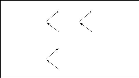
Unconditional call: for example JU PB5
The program block is executed without regard to the RLO.
Conditional call: for example JC PB6
The program block is executed in dependence on the RLO.
PB 1 |
|
|
PB 5 |
|
|
|
PB 10 |
|
|
|
|
A |
I 1.0 |
|
|
A I 2.0 |
|
JU |
PB5 |
|
|
|
|
|
|
|
|
JC |
PB10 |
|
|
|
|||
O |
I 5.3 |
|
|
|
|
|||
|
|
|
|
|
|
|
||
|
|
|
BE |
|
|
|
BE |
|
|
|
|
PB 6 |
|
|
|
|
|
A |
I 1.5 |
|
O |
I 3.0 |
|
|
|
|
|
|
|
|
|
|
|
||
JC |
PB 6 |
|
|
|
|
|
|
|
A |
I3.2 |
|
|
|
|
|
|
|
BE |
|
|
BE |
|
|
|
|
|
Block calls for enabling execution of a program block
2-2 |
© Siemens AG 1990 All Rights Reserved 6ZB5 410-0CM02 |
SINUMERIK 805 (PJ)
10.90 |
3 Data Blocks |
3.1 Programmig data blocks
3 Data Blocks
3.1Programming Data Blocks
The data required by the user program is stored in data blocks (DBs). No STEP 5 operations are programmed in these blocks.
Data may be:
·Arbitrary bit patterns, e. g. for plant status indications
·Numbers (hexadecimal, binary, decimal), e. g. for times and results of arithmetic operations
·Alphanumeric characters, e. g. for message texts
Generation of a data block on the programmer begins by specifying a data block number between 1 and 255. Each data block (example: DB99) may comprises as many as 256 data words (of 16 bits each). The data must be entered by word, beginning with data word 0.
One word is reserved in program memory for each data word. The programmer also generates a block header for each data block; the header takes up five words in program memory.
The operating system generates data blocks DB1 (diagnostics DB), DB36 (read/write job status for NC data) and DB37 (initialize the two V.24 (RS232C) interfaces) in the controller©s restart routine. The programmer (PG) prevents deletion of these blocks (message 70: DB in EPROM).
For test purposes, however, the user can invoke the ºForce Variableº programmer function if he wants to view or modify data words.
|
DB |
|
|
|
|
|
Block header |
DW0 |
|
|
|
|
|
|
|
|
|
|
|
|
|
||
|
|
|
|
|
|
||
|
|
|
|
|
|
|
|
|
|
|
|
|
|
|
|
|
O |
|
|
||||
|
|
||||||
DW1 |
3 F |
|
4 A |
|
|||
DW2 |
0110 0100 0000 1111 |
|
|
|
|
||
DW3 |
2 |
|
U |
|
|||
DW4 |
|
O |
|
||||
DW5 |
|
O |
|||||
|
|
|
|
|
|
|
Data words |
|
|
|
|||||
|
|
|
|
|
|
|
1 to 255 |
|
|
|
|
|
|
|
|
DW255
Structure of a data block
© Siemens AG 1990 All Rights Reserved 6ZB5 410-0CM02 |
3-1 |
SINUMERIK 805 (PJ)
3 Data Blocks |
10.90 |
3.2 Calling data blocks
3.2Calling data blocks
Data blocks can be called unconditionally only. Once called, a data block remains in force until the next is invoked.
User data blocks must not conflict with those required by the system.
A data block call can be programmed in an organization, program, function or sequence block. The ºA DB xxxº command calls a data block, e.g. (DB10, i.e. call from DB 10).
Example 1
Transferring the contents of data word 1, data block 10 to data word 1, data block 20.
:C |
DB10 |
|
|
DB 10 |
|
|
|
|
|
:L |
DW1 |
DW0 |
|
|
|
|
|
|
|
DW1 |
|
|
|
|
|
|
|||
:C |
DB20 |
|
|
|
|
|
|
||
|
|
|
|
|
|
|
|
||
:T |
DW1 |
|
|
|
|
|
|
|
|
|
|
DW255 |
|
|
|
|
|
|
|
|
|
DW0 |
|
DB 20 |
|
|
|
||
|
|
|
|
|
|
|
|
||
|
|
DW1 |
|
|
|
|
|
|
|
|
|
|
|
|
|
|
|
||
|
|
|
|
|
|
|
|
|
|
|
|
|
|
|
|
|
|
|
|
Calling a data block
Example 2
When a program block in which a data block has already been addressed calls another program block that addresses another data block, the latter is valid only in the program block that was called. The original data block is again valid following return to the calling block.
PB 7 |
|
|
PB 20 |
C |
DB10 |
||
DB 10 is open
SPA PB20 |
C DB11 |
DB 11 is open
|
|
|
|
|
|
BE |
BE |
|
Validity range of a selected data block
3-2 |
© Siemens AG 1990 All Rights Reserved 6ZB5 410-0CM02 |
|
SINUMERIK 805 (PJ) |

05.93 |
3 Data blocks |
3.3 Data blocks created by the system program
3.3Data blocks created by the system program
DB 1: Diagnostics DB
(for details see Section 8.1)
DB 28: Analog setpoint value output
DB 36: Status data transfer for FB 61/62
DB 37: Serial
For more detailed information on data blocks DB28, DB36 and DB37 please refer to
Interface Description Part 1, Signals.
© Siemens AG 1990 All Rights Reserved 6ZB5 410-0CM02 |
3±3 |
SINUMERIK 805 (PJ)
10.90 |
4 Function Blocks |
4.1 General remarks
4 Function Blocks
4.1General remarks
Function blocks are used to implement frequently recurring or extremely complex functions.
Functions blocks (FBs) are as much a part of the user program as, for example, program blocks. There are three basic differences between function blocks and organization, program or sequence blocks:
·Function block can be initialized, i. e. a function block©s formal parameters can be replaced by the actual operands with which the function block is called.
·In contrast to organization, program and sequence blocks, an extended operation set comprising the STEP 5 supplementary operations (see also Section 9.4) can be used to program function blocks, and only function blocks.
·The program in a function block can be generated and logged in statement list form only.
The function blocks in a user program represent complex, self-contained functions. A function block programmed in the STEP 5 language can be programmed by the user himself, or may be purchased from Siemens as a software product. In addition, a number of pretested, technology-specific function blocks can be assembled to form function macros and linked into the basic program. The user can call these macros as he would a function block, but he cannot modify them. These blocks are written in assembly language and are also referred to as ºresidentº or integral function blocksº (cf. Section 6.1).
© Siemens AG 1990 All Rights Reserved 6ZB5 410-0CM02 |
4-1 |
SINUMERIK 805 (PJ)

4 Function Blocks |
10.90 |
4.2 Structure of function blocks
4.2Structure of function blocks
A function block comprises a block header, name and parameter declaration, and the block body.
Block header
Name and parameter declarations
Block body with STEP 5 program or assembly language statements
Structure of a function block
4.2.1Block header
The block header contains all information which the programmer needs in order to display the function block in graphic form and check the operands when the function block is initialized. The user must enter the header (using the programmer) before programming the function block.
4.2.2Block body
The block body contains the actual program, i. e. describes the function to be executed in the STEP 5 language. Only the block body is processed when the function block is called.
The programmer echoes the block name and parameter declaration when integral assemblylanguage function blocks are called.
When the ºfirst executable statementº in the block body is the ºASMº STEP 5 command (switch to assembly code), the processor executes the subsequent assembly language statements immediately.
4-2 |
© Siemens AG 1990 All Rights Reserved 6ZB5 410-0CM02 |
SINUMERIK 805 (PJ)
10.90 |
4 Function Blocks |
4.3 Calling and initializing function blocks
4.3Calling and initializing function blocks
Function blocks (FBs) are present only once in memory. They can be called once or more than once by a block, and different parameters can be used for each call.
Function blocks are programmed or called by specifying a block number (FB 0 to 255).
A function block call can be programmed in an organization, sequence or program block or in another function block. A call comprises the call statement and the parameter list.
4.3.1Call statement
Unconditional call: e.g. JU FB 30
The function block is executed without regard to the RLO.
Conditional call: e.g. JC FB 35
The function block is executed only when the RLO is in signal state º1º.
4.3.2Parameter list
The parameter list immediately follows the call statement, and defines all input variables, output variables and data. The parameter list may contain no more than 40 variables.
The variables from the parameter list replace the formal parameters when the function block is executed. The programmer (PG) monitors the order in which the variables are entered in the parameter list.
The programmer automatically generates, but does not display, the jump statement that follows the FB call.
The FB call reserves two words in program memory, and each parameter one additional word.
The identifiers for the function block©s inputs and outputs and the name of the function block are displayed on the programmer when the user programs the function block.
This information is in the function block itself. It is therefore necessary that all required function blocks either be resident as function macro in the PLC©s basic software, be transferred to the program diskette, or be entered directly into the programmable controller©s program memory before function block programming can begin (for details, refer to the Operating Instructions).
© Siemens AG 1990 All Rights Reserved 6ZB5 410-0CM02 |
4-3 |
SINUMERIK 805 (PJ)
Loading...