


840D
Table of contents
 Loading...
Description of Functions 03/2004 Edition
SINUMERIK 840D/840Di/810D
Synchronized Actions


Valid for
Control Software Version
SINUMERIK 840D powerline 7
SINUMERIK 840DE powerline 7
SINUMERIK 840Di 3
SINUMERIK 840DiE (export version) 3
SINUMERIK 810D powerline 7
SINUMERIK 810DE powerline 7
03.2004 Edition
SINUMERIK 840D/840Di/810D
Synchronized Actions
Description of Functions
Brief Description 1
Detailed Description 2
Supplementary Conditions 3
Data Descriptions (MD, SD) 4
Signal Descriptions 5
Examples 6
Data Fields, Lists 7
References A
Index B

Further information is available on the Internet under:
http://www.siemens.com/motioncontrol
This publication was produced with Interleaf V7.
The reproduction, transmission or use of this document or its
contents is not permitted without express written authority. Offenders
will be liable for damages. All rights, including those created by patent
grant or registration of a utility model or design, are reserved.
Siemens AG, 1994–2004. All rights reserved
Other functions not described in this documentation might be
executable in the control. However, no claim can be made regarding
the availability of these functions when the equipment is first supplied
or for service cases.
We have checked that the contents of this document correspond to
the hardware and software described. Nonetheless, differences might
exist and therefore we cannot guarantee that they are completely
identical. The information contained in this document is, however,
reviewed regularly and any necessary changes will be included in the
next edition. We welcome suggestions for improvement.
Subject to changes without prior notice
Siemens AktiengesellschaftOrder No. 6FC5 297-7AD40-0BP0
Printed in German
y
SINUMERIK
Documentation
Printing history
Brief details of this edition and previous editions are listed below.
The status of each edition is shown by the code in the “Remarks” column.
Status code in the “Remarks” column:
A New documentation.. . . . .
B Unrevised reprint with new order no.. . . . .
C Revised edition with new status. . . . . .
If factual changes have been made on the page in relation to the same software
version, this is indicated by a new edition coding in the header on that page.
06.94 6FC5 297–0AC30–0BP0 A
08.94 6FC5 297–0AC30–0BP1 C
02.95 6FC5 297–2AC30–0BP0 C
04.95 6FC5 297–2AC30–0BP1 C
09.95 6FC5 297–3AC30–0BP0 C
03.96 6FC5 297–3AC30–0BP1 C
08.97 6FC5 297–4AD40–0BP0 A
1)
12.97 6FC5 297–4AD40–0BP1 C
12.98 6FC5 297–5AD40–0BP0 C
08.99 6FC5 297–5AD40–0BP1 C
04.00 6FC5 297–5AD40–0BP2 C
10.00 6FC5 297–6AD40–0BP0 C
09.01 6FC5 297–6AD40–0BP1 C
11.02 6FC5 297–6AD40–0BP2 C
03.04 6FC5 297–7AD40–0BP0 C
1)
This
document
replaces
the
S5
function
described
for
older
software
versions
in
the
“Description
of
Functions:
Extended
Functions”
brochure.
This book is part of the documentation on CD-ROM (DOCONCD)
Edition Order No. Remarks
03.04 6FC5 298–7CA00–0BG0 C
Trademarks
SIMATICr, SIMATIC HMIr, SIMATIC NETr, SIROTECr, SINUMERIKr and SIMODRIVEr are registered
trademarks of Siemens AG. The remaining designations in this brochure may be trademarks, the use of
which by third parties for their own purposes may violate the rights of the respective owners.
3ls

03.04
Synchronized Actions (FBSY)
v
Siemens AG, 2004. All rights reserved
SINUMERIK 840D/840Di/810D Descr. of Functions Synchronized Actions (FBSY) – 03.04 Edition
Preface
The SINUMERIK documentation is organized on three levels:
S General documentation
S User documentation
S Manufacturer/service documentation
This document is designed for machine tool manufacturers. The brochure con-
tains a detailed description of the scope of functions offered by SINUMERIK
840D/810D controllers.
The function descriptions are only valid for the specific software version or up to
the software version specified. You should request valid function descriptions
for new software versions. Old function descriptions are only partly applicable
for new software versions.
For more detailed information on SINUMERIK 840D/840Di/810D publications
and other publications covering all SINUMERIK controls (e.g. universal inter-
face, measuring cycles, etc.) please contact your local Siemens office.
Note
It may be possible to run functions that are not described in this document in your controller.
This does not, however, represent an obligation to supply such functions with a new control
or when servicing.
If you have queries regarding the control system, please contact the following
hotline:
A&D Technical Support Phone: ++49-(0)180-5050-222
Fax: ++49-(0)180-5050-223
Email: adsupport@siemens.com
If you have queries regarding documentation (suggestions, corrections), please
send a fax to the following fax address:
Fax: ++49-(0)9131-98-2176
Email: motioncontrol.docu@erlf.siemens.de
Fax form: See the feedback page at the end of the document
http://www.siemens.com/motioncontrol
Notes for the
reader
Hotline
Internet address
for SINUMERIK
09.01

03.04
Synchronized Actions (FBSY)
vi
Siemens AG, 2004. All rights reserved
SINUMERIK 840D/840Di/810D Descr. of Functions Synchronized Actions (FBSY) – 03.04 Edition
Improved-performance variants
S SINUMERIK 840D powerline and
S SINUMERIK 840DE powerline
will be available from 09.2001 onwards. For a list of available powerline
modules, please refer to Section 1.1 of the Hardware Description /PHD/.
Improved-performance variants
S SINUMERIK 810D powerline and
S SINUMERIK 810DE powerline
will be available from 12.2001 onwards. For a list of available powerline
modules, please refer to Section 1.1 of the Hardware Description /PHC/.
This document describes the synchronized actions function for SINUMERIK
840D SW 4 and later and for SINUMERIK 810D SW 2 and later. It replaces the
S5 function described for older software versions in the “Description of
Functions: Extended Functions” brochure.
The function descriptions provide the information required for configuration and
installation.
The information contained in the function descriptions is designed for:
S Design engineers
S PLC programmers creating the PLC user program with the signals listed
S Start-up engineers once the system has been configured and set up
S Maintenance personnel inspecting and interpreting status signals and
alarms
!
Important
This document is valid for the following controls:
D SINUMERIK 840D powerline,
software version 7
D SINUMERIK 810D powerline,
software version 7
D SINUMERIK 840Di,
software version 3
The SW versions indicated in this document refer to the SINUMERIK 840D and
810D controls. For detailed information about which function is enabled for
which controller, see /BU/, Catalog NC 60 (this information is not provided in this
document). Equivalents are as follows:
SINUMERIK 840D
powerline
SINUMERIK 810D
powerline
Objective
Target groups
Equivalent NC
software versions
10.0009.01

03.04
Synchronized Actions (FBSY)
vii
Siemens AG, 2004. All rights reserved
SINUMERIK 840D/840Di/810D Descr. of Functions Synchronized Actions (FBSY) – 03.04 Edition
Table 1-1 Equivalent software version
SINUMERIK 840D pow-
erline
SINUMERIK 810D pow-
erline
SINUMERIK 840Di
7.1 Corre-
sponds to
7.1 3.1
!
Danger
Indicates an imminently hazardous situation which, if not avoided, will result in
death or serious injury or in substantial property damage.
!
Warning
Indicates a potentially hazardous situation which, if not avoided, could result in
death or serious injury or in substantial property damage.
!
Caution
Used with the safety alert symbol indicates a potentially hazardous situation
which, if not avoided, may result in minor or moderate injury or in property dam-
age.
Caution
Used without safety alert symbol indicates a potentially hazardous situation
which, if not avoided, may result in property damage.
Notice
Used without the safety alert symbol indicates a potential situation which, if not
avoided, may result in an undesirable result or state.
!
Important
Important indicates an important or especially relevant item of information.
Symbols
10.0009.0109.0110.00

03.04
Synchronized Actions (FBSY)
viii
Siemens AG, 2004. All rights reserved
SINUMERIK 840D/840Di/810D Descr. of Functions Synchronized Actions (FBSY) – 03.04 Edition
Note
This note contains additional important information.
10.00

03.04
Synchronized Actions (FBSY)
ix
Siemens AG, 2004. All rights reserved
SINUMERIK 840D/840Di/810D Descr. of Functions Synchronized Actions (FBSY) – 03.04 Edition
Contents
1 Brief Description 1-13. . . . . . . . . . . . . . . . . . . . . . . . . . . . . . . . . . . . . . . . . . . . . . . . . .
2 Detailed Description 2-15. . . . . . . . . . . . . . . . . . . . . . . . . . . . . . . . . . . . . . . . . . . . . . .
2.1 Components of synchronized actions 2-15. . . . . . . . . . . . . . . . . . . . . . . . .
2.1.1 Definition of motion-synchronous actions 2-21. . . . . . . . . . . . . . . . . . . . . .
2.1.2 Execution of synchronized actions 2-21. . . . . . . . . . . . . . . . . . . . . . . . . . .
2.1.3 List of possible actions 2-22. . . . . . . . . . . . . . . . . . . . . . . . . . . . . . . . . . . . .
2.2 Real-time evaluations and calculations 2-23. . . . . . . . . . . . . . . . . . . . . . . .
2.3 Special real-time variables for synchronized actions 2-29. . . . . . . . . . . .
2.3.1 Marker/counter variables 2-29. . . . . . . . . . . . . . . . . . . . . . . . . . . . . . . . . . . .
2.3.2 Timers 2-30. . . . . . . . . . . . . . . . . . . . . . . . . . . . . . . . . . . . . . . . . . . . . . . . . . .
2.3.3 Synchronized action parameters 2-31. . . . . . . . . . . . . . . . . . . . . . . . . . . . .
2.3.4 R parameters 2-32. . . . . . . . . . . . . . . . . . . . . . . . . . . . . . . . . . . . . . . . . . . . .
2.3.5 Machine and setting data 2-32. . . . . . . . . . . . . . . . . . . . . . . . . . . . . . . . . . .
2.3.6 FIFO variables (circulating memory) 2-33. . . . . . . . . . . . . . . . . . . . . . . . . .
2.3.7 System variables saved in SRAM (SW 6.3 and later) 2-36. . . . . . . . . . .
2.3.8 Determining the path tangent in synchronized actions 2-37. . . . . . . . . . .
2.3.9 Determining the current override 2-38. . . . . . . . . . . . . . . . . . . . . . . . . . . . .
2.3.10 Capacity evaluation using time requirement for synchronized
actions 2-39. . . . . . . . . . . . . . . . . . . . . . . . . . . . . . . . . . . . . . . . . . . . . . . . . . .
2.3.11 List of system variables relevant to synchronized actions 2-42. . . . . . . .
2.4 Actions in synchronized actions 2-43. . . . . . . . . . . . . . . . . . . . . . . . . . . . . .
2.4.1 Output of M, S and H auxiliary functions to PLC 2-45. . . . . . . . . . . . . . . .
2.4.2 Setting (writing) and reading of real-time variables 2-47. . . . . . . . . . . . . .
2.4.3 Alteration of SW cam positions and times (setting data) 2-48. . . . . . . . .
2.4.4 FCTDEF 2-49. . . . . . . . . . . . . . . . . . . . . . . . . . . . . . . . . . . . . . . . . . . . . . . . .
2.4.5 Polynomial evaluation SYNFCT 2-51. . . . . . . . . . . . . . . . . . . . . . . . . . . . . .
2.4.6 Overlaid movements $AA_OFF settable (SW 6 and later) 2-56. . . . . . .
2.4.7 Online tool offset FTOC 2-58. . . . . . . . . . . . . . . . . . . . . . . . . . . . . . . . . . . .
2.4.8 RDISABLE 2-60. . . . . . . . . . . . . . . . . . . . . . . . . . . . . . . . . . . . . . . . . . . . . . . .
2.4.9 STOPREOF 2-60. . . . . . . . . . . . . . . . . . . . . . . . . . . . . . . . . . . . . . . . . . . . . .
2.4.10 DELDTG 2-60. . . . . . . . . . . . . . . . . . . . . . . . . . . . . . . . . . . . . . . . . . . . . . . . .
2.4.11 Disabling a programmed axis motion 2-62. . . . . . . . . . . . . . . . . . . . . . . . .
2.4.12 Starting command axes 2-62. . . . . . . . . . . . . . . . . . . . . . . . . . . . . . . . . . . .
2.4.13 Axial feedrate from synchronized actions 2-65. . . . . . . . . . . . . . . . . . . . . .
2.4.14 Starting/Stopping axes from synchronized actions 2-66. . . . . . . . . . . . . .
2.4.15 Spindle motions from synchronized actions 2-66. . . . . . . . . . . . . . . . . . . .
2.4.16 Setting actual values from synchronized actions 2-70. . . . . . . . . . . . . . .
2.4.17 Coupled motions and activating/deactivating couplings 2-71. . . . . . . . . .
2.4.18 Measurements from synchronized actions 2-74. . . . . . . . . . . . . . . . . . . . .
2.4.19 Setting and deletion of wait markers for channel synchronization 2-78.
2.4.20 Setting alarm/error reactions 2-79. . . . . . . . . . . . . . . . . . . . . . . . . . . . . . . .
2.4.21 Evaluating data for machine maintenance 2-80. . . . . . . . . . . . . . . . . . . . .
2.5 Calling technology cycles 2-82. . . . . . . . . . . . . . . . . . . . . . . . . . . . . . . . . . .
2.5.1 Coordination of synchronized actions, technology cycles, part
program (and PLC) 2-85. . . . . . . . . . . . . . . . . . . . . . . . . . . . . . . . . . . . . . . .
2.6 Control and protection of synchronized actions 2-87. . . . . . . . . . . . . . . . .
2.6.1 Control via PLC 2-87. . . . . . . . . . . . . . . . . . . . . . . . . . . . . . . . . . . . . . . . . . .
2.6.2 Protected synchronized actions 2-89. . . . . . . . . . . . . . . . . . . . . . . . . . . . . .
03.04

03.04
Synchronized Actions (FBSY)
x
Siemens AG, 2004. All rights reserved
SINUMERIK 840D/840Di/810D Descr. of Functions Synchronized Actions (FBSY) – 03.04 Edition
2.7 Control system response for synchronized actions in specific
operational states 2-92. . . . . . . . . . . . . . . . . . . . . . . . . . . . . . . . . . . . . . . . . .
2.7.1 POWER ON 2-92. . . . . . . . . . . . . . . . . . . . . . . . . . . . . . . . . . . . . . . . . . . . . .
2.7.2 RESET 2-92. . . . . . . . . . . . . . . . . . . . . . . . . . . . . . . . . . . . . . . . . . . . . . . . . . .
2.7.3 NC STOP 2-93. . . . . . . . . . . . . . . . . . . . . . . . . . . . . . . . . . . . . . . . . . . . . . . . .
2.7.4 Mode change 2-94. . . . . . . . . . . . . . . . . . . . . . . . . . . . . . . . . . . . . . . . . . . . .
2.7.5 End of program 2-94. . . . . . . . . . . . . . . . . . . . . . . . . . . . . . . . . . . . . . . . . . . .
2.7.6 Response of active synchronized actions to end of program and
change in operating mode 2-95. . . . . . . . . . . . . . . . . . . . . . . . . . . . . . . . . .
2.7.7 Block search 2-95. . . . . . . . . . . . . . . . . . . . . . . . . . . . . . . . . . . . . . . . . . . . . .
2.7.8 Program interruption by ASUB 2-96. . . . . . . . . . . . . . . . . . . . . . . . . . . . . . .
2.7.9 REPOS 2-96. . . . . . . . . . . . . . . . . . . . . . . . . . . . . . . . . . . . . . . . . . . . . . . . . .
2.7.10 Response to alarms 2-96. . . . . . . . . . . . . . . . . . . . . . . . . . . . . . . . . . . . . . . .
2.8 Configuration 2-97. . . . . . . . . . . . . . . . . . . . . . . . . . . . . . . . . . . . . . . . . . . . . .
2.8.1 Configurability 2-97. . . . . . . . . . . . . . . . . . . . . . . . . . . . . . . . . . . . . . . . . . . . .
2.9 Diagnostics (with MMC 102/MMC 103 only) 2-99. . . . . . . . . . . . . . . . . . .
2.9.1 Display status of synchronized actions 2-100. . . . . . . . . . . . . . . . . . . . . . . .
2.9.2 Display real-time variables 2-100. . . . . . . . . . . . . . . . . . . . . . . . . . . . . . . . . .
2.9.3 Log real-time variables 2-101. . . . . . . . . . . . . . . . . . . . . . . . . . . . . . . . . . . . .
3 Supplementary Conditions 3-103. . . . . . . . . . . . . . . . . . . . . . . . . . . . . . . . . . . . . . . . .
4 Data Descriptions (MD, SD) 4-105. . . . . . . . . . . . . . . . . . . . . . . . . . . . . . . . . . . . . . . . .
4.1 General machine data 4-105. . . . . . . . . . . . . . . . . . . . . . . . . . . . . . . . . . . . . .
4.2 Channelspecific machine data 4-107. . . . . . . . . . . . . . . . . . . . . . . . . . . . . . .
4.3 Axis/spindlespecific machine data 4-111. . . . . . . . . . . . . . . . . . . . . . . . . . .
4.4 Setting data 4-113. . . . . . . . . . . . . . . . . . . . . . . . . . . . . . . . . . . . . . . . . . . . . . .
5 Signal Descriptions 5-115. . . . . . . . . . . . . . . . . . . . . . . . . . . . . . . . . . . . . . . . . . . . . . . .
6 Examples 6-117. . . . . . . . . . . . . . . . . . . . . . . . . . . . . . . . . . . . . . . . . . . . . . . . . . . . . . . . .
6.1 Examples of conditions in synchronized actions 6-117. . . . . . . . . . . . . . . .
6.2 Reading and writing of SD/MD from synchronized actions 6-118. . . . . . .
6.3 Examples of adaptive control 6-120. . . . . . . . . . . . . . . . . . . . . . . . . . . . . . . .
6.3.1 Clearance control with variable upper limit 6-120. . . . . . . . . . . . . . . . . . . . .
6.3.2 Feedrate control 6-121. . . . . . . . . . . . . . . . . . . . . . . . . . . . . . . . . . . . . . . . . . .
6.3.3 Control velocity as a function of normalized path 6-123. . . . . . . . . . . . . . .
6.4 Monitoring of a safety clearance between two axes 6-124. . . . . . . . . . . . .
6.5 Store execution times in R parameters 6-124. . . . . . . . . . . . . . . . . . . . . . . .
6.6 “Centering” with continuous measurement 6-125. . . . . . . . . . . . . . . . . . . . .
6.7 Axis couplings via synchronized actions 6-128. . . . . . . . . . . . . . . . . . . . . . .
6.7.1 Coupling to leading axis 6-128. . . . . . . . . . . . . . . . . . . . . . . . . . . . . . . . . . . .
6.7.2 Non-circular grinding via master value coupling 6-129. . . . . . . . . . . . . . . .
6.7.3 On-the-fly parting 6-131. . . . . . . . . . . . . . . . . . . . . . . . . . . . . . . . . . . . . . . . . .
6.8 Technology cycles position spindle 6-133. . . . . . . . . . . . . . . . . . . . . . . . . . .
6.9 Synchronized actions in the TCC/MC area 6-134. . . . . . . . . . . . . . . . . . . .

03.04
Synchronized Actions (FBSY)
xi
Siemens AG, 2004. All rights reserved
SINUMERIK 840D/840Di/810D Descr. of Functions Synchronized Actions (FBSY) – 03.04 Edition
7 Data Fields, Lists 7-139. . . . . . . . . . . . . . . . . . . . . . . . . . . . . . . . . . . . . . . . . . . . . . . . . .
7.1 Interface signals 7-139. . . . . . . . . . . . . . . . . . . . . . . . . . . . . . . . . . . . . . . . . . .
7.2 Machine data 7-139. . . . . . . . . . . . . . . . . . . . . . . . . . . . . . . . . . . . . . . . . . . . .
7.3 Alarms 7-141. . . . . . . . . . . . . . . . . . . . . . . . . . . . . . . . . . . . . . . . . . . . . . . . . . .

03.04
Synchronized Actions (FBSY)
xii
Siemens AG, 2004. All rights reserved
SINUMERIK 840D/840Di/810D Descr. of Functions Synchronized Actions (FBSY) – 03.04 Edition
Notes

03.04
Synchronized Actions (FBSY)
1-13
Siemens AG, 2004. All rights reserved
SINUMERIK 840D/840Di/810D Descr. of Functions Synchronized Actions (FBSY) – 03.04 Edition
Brief Description
Motion-synchronous actions (or “synchronized actions” for short) are instruc-
tions programmed by the user, which are evaluated in the interpolation cycle of
the NCK in synchronism with part program execution. If the condition pro-
grammed in the synchronized action is fulfilled or if none is specified, then ac-
tions assigned to the instruction are activated in synchronism with the remain-
der of the part program run.
The following selection from the wide range of possible applications indicates
how actions programmed in synchronized actions can be usefully employed.
S Output of auxiliary functions to PLC
S Writing and reading of real-time variables
S Positioning of axes and spindles
S Activation of synchronous procedures such as:
– Readin disable
– Deletion of distance-to-go
– End preprocessing stop
S Activation of technology cycles
S Online calculation of function values
S Online tool offsets
S Activation/deactivation of couplings/coupled motion
S Take measurements
S Enabling/disabling of synchronized actions
All possible applications of this function are described in the “Detailed Descrip-
tion” chapter.
Definition of
synchronized
actions
Applications
1 Brief Descri
p
tion
1
03.04
Synchronized Actions (FBSY)
1-14
Siemens AG, 2004. All rights reserved
SINUMERIK 840D/840Di/810D Descr. of Functions Synchronized Actions (FBSY) – 03.04 Edition
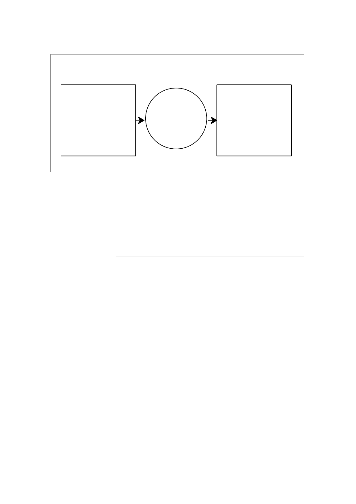
In NCK interpolation cycle:
Real-time events and
values:
– Digital inputs/signals
– Values of system
variables
– Measured values
– Drive data
Gating logic
– Evaluation of
conditions
Initiated actions:
– Non-modal
– Modal
– Static modal (across
different operating modes)
Fig. 1-1 Schematic diagram of synchronized actions
For details of how to program synchronized actions, please see
Reference: /PGA/, Programming Guide Advanced
The following chapters describe:
– Functional conditions for synchronized actions (Chapter 2),
– The required machine data (Chapter 4),
– Example applications (Chapter 6).
Note
This Description of Functions applies to the functionality provided in SW 5. The
functions of synchronized actions in SW versions up to and including 3 are
described in:
References: /FB/, S5, “Synchronized Actions”
J
1 Brief Descri
p
tion
12.98

03.04
Synchronized Actions (FBSY)
2.1 Components of synchronized actions
2-15
Siemens AG, 2004. All rights reserved
SINUMERIK 840D/840Di/810D Descr. of Functions Synchronized Actions (FBSY) – 03.04 Edition
Detailed Description
2.1 Components of synchronized actions
Component: Validity,
identifica-
tion number
Frequency G code for
cond. and
action
Condition Action
code word
(fixed)
G code for
action
Action or
technology
cycle
see 2.5
Example: IDS=1 EVERY G70 $AAA_IM[B]
> 15
DO G71 POS[X]= 100
The components of a synchronized action, i.e.:
S Validity:
– With identification number
– Without identification number
S Frequency
S G code for condition and action (SW 5 and later)
S Condition
S G code for actions (SW 5 and later)
S Action(s)/Technology cycle
are explained individually below.
There are three possible for defining the scope of validity of a synchronized
action:
S No status
S ID
S IDS
Structure of a
synchronized
action
Validity, ID number
2

03.04
2.1 Components of synchronized actions
Synchronized Actions (FBSY)
2-16
Siemens AG, 2004. All rights reserved
SINUMERIK 840D/840Di/810D Descr. of Functions Synchronized Actions (FBSY) – 03.04 Edition
Synchronized actions that have no specified validity have a non-modal action,
i.e. they apply only to the next block.
Non-modal synchronized actions are operative only in AUTOMATIC mode.
In SW 6.1 and later, non-modal synchronized actions are active modally for all
preprocessing stop blocks (incl. implicitly generated ones) and for implicitly gen-
erated intermediate blocks.
Synchronized actions with validity identifier ID are modally active in subse-
quently programmed blocks. They are operative only in AUTOMATIC mode.
Limitation:
– ID actions remain operative only until another synchronized action with
the same identification number is programmed
– Until they are canceled with CANCEL(i), see Subsection 2.5.1.
Static synchronized actions that are programmed with keyword “IDS” are active
in all operating modes. They are also referred to as s
tatic synchronized ac-
tions. Option.
Synchronized actions programmed with ID or IDS are deleted from the part pro-
gram.
For modal synchronized actions (ID, IDS) identification numbers between 1 and
255 are allocated. They are important for the functions of mutual coordination of
synchronized actions. See Subsection 2.5.1. Modal/static synchronized actions
with identification numbers between 1 and 64 can be disabled and enabled from
the PLC. See Subsection 2.6.1.
Unique identification numbers must be allocated in the channel.
Applications for static synchronized actions:
– AC grinding (also active in JOG mode)
– Gating logic for Safety Integrated
– Monitoring functions, reaction to machine states in all operating modes
– Optimization of tool change
– Cyclic machines
Examples:
IDS=1 EVERY $A_IN[1]==1 DO POS[X]=100 All operating modes
ID=2 EVERY $A_IN[1]==0 DO POS[X]=0 AUTOMATIC
Note
The following actions are operative only in AUTOMATIC mode when the
program is running:
STOPREOF,
DELDTG
No specified validity
ID
IDS
Identification
numbers
10.00

03.04
Synchronized Actions (FBSY)
2.1 Components of synchronized actions
2-17
Siemens AG, 2004. All rights reserved
SINUMERIK 840D/840Di/810D Descr. of Functions Synchronized Actions (FBSY) – 03.04 Edition
Keywords (see table) are programmed to indicate how often the subsequently
specified condition must be scanned and the associated action executed if the
condition is fulfilled. These keywords are an integral component of the synchro-
nized action condition.
Table 2-1 Effect of frequency keywords
Keyword Scanning frequency
None
If no scanning frequency is programmed, then the action is executed cyclically in every
interpolation cycle.
WHENEVER
The associated action/technology cycle is executed cyclically in every interpolation cycle
provided that the condition is fulfilled.
FROM
If the condition has been fulfilled once, the action/technology cycle is executed cycli-
cally in every interpolation cycle for as long as the synchronized action remains active.
WHEN
As soon as the condition has been fulfilled, the action/technology cycle is executed
once. Once the action has been executed a single time, the condition is no longer
checked.
EVERY
The action/technology cycle is activated once if the condition if fulfilled. The action/
technology cycle is executed every time the condition changes from the “FALSE” to
the “TRUE” state. In contrast to keyword WHEN, checking of the condition continues
after execution of the action/cycle until the synchronized action is deleted or disabled.
For details of technology cycles, please see Section 2.5.
Deselecting (deleting) an active synchronized action from the part program with
CANCEL has no effect on the active action. Positioning motions are completed
as programmed. The CANCEL command can be programmed to delete a
modal or static synchronized action. If a synchronized action is deleted while
the positioning axis motion it has initiated is still in progress, the positioning mo-
tion continues until properly executed. A channel stop also cancels the position-
ing movement from synchronized actions/technology cycles.
In SW 5 and later, G codes can be programmed in synchronized actions. This
allows defined settings to exist for the evaluation of the condition and the action/
technology cycle to be executed, independent of the current part program sta-
tus. It is necessary to separate the synchronized actions from the program envi-
ronment, because synchronized actions are required to execute their actions at
any time from a defined initial state as a result of fulfilled trigger conditions.
Applications:
Definition of the systems of measurement for condition evaluation and action
through G codes G70, G71, G700, G710.
Note
In SW 5, the use of the G codes in synchronized actions is limited to these 4 G
codes.
Frequency
Deletion
G code for
condition and
action

03.04
2.1 Components of synchronized actions
Synchronized Actions (FBSY)
2-18
Siemens AG, 2004. All rights reserved
SINUMERIK 840D/840Di/810D Descr. of Functions Synchronized Actions (FBSY) – 03.04 Edition
A G code specified for the condition is valid for the evaluation of the condition
and for the action if no separate G code is specified for the action.
Only one G code of the G code group may be programmed for each part of the
condition.
Execution of actions/technology cycles can be made dependent upon a condi-
tion (logical expression).
The condition is checked in the interpolation cycle. If no condition is pro-
grammed, the action is performed once in every IPO cycle. In SW version 3 and
earlier, two conditions are permitted, i.e. the comparison of a real-time variable
with an expression calculated during preprocessing or the comparison of two
real-time variables.
Examples:
WHENEVER $AA_IM[X] > 10.5*SIN(45) DO .... or
WHENEVER $AA_IM[X] > $$AA_IM[X1] DO ...
An additional condition is available in SW 4 and later, i.e. the linking of compari-
sons using Boolean operations. Boolean operators in NC language may be
used for this purpose:
NOT, AND, OR, XOR, B_OR, B_AND, B_XOR, B_NOT.
Examples:
WHENEVER ($A_IN[1]==1) OR ($A_IN[3]==0) DO ...
; while input 1 is applied or input 3 is not applied ...
Two or more real-time expressions may be compared with one another within
one condition.
Comparisons may be made between variables of the same type or between
partial expressions.
Example:
WHEN $AA_IM[X2] <= $AA_IM[X1] +.5 DO $AA_OVR[X1]=0
; Stop when safety clearance is exceeded
The options for applying real-time expressions are described in the “Calcula-
tions in real time” chapter. When conditions are programmed, all the system
variables listed in Subsection 2.3.11 can be addressed. In addition:
S Machine data, e.g. $$MN_..., $$MC_..., $$MA_...
S Setting data, e.g. $$SN_..., $$SC_..., $$SA_...
Note
S GUD variables cannot be used
S R parameters are addressed with $R....
S Setting and machine data whose value may vary during
machining must be programmed with $$S._... / $$M._...
Further examples of conditions can be found in Section 6.1.
Conditions

03.04
Synchronized Actions (FBSY)
2.1 Components of synchronized actions
2-19
Siemens AG, 2004. All rights reserved
SINUMERIK 840D/840Di/810D Descr. of Functions Synchronized Actions (FBSY) – 03.04 Edition
This G code may specify a G code for all actions in the block and technology
cycles, which differs from the one set in the condition. If technology cycles are
contained in the action part, the G code remains modally active for all actions
until the next G code, even after the technology cycle has been completed.
Only one G code of the G code group may be programmed for each action part.
Every synchronized action contains one or more programmed actions or one
technology cycle. These are executed when the appropriate condition is ful-
filled. If several actions are programmed in one synchronized action, they are
executed within the same interpolation cycle.
Example: WHEN $AA_IM[Y] >= 35.7 DO M135 $A_OUT[1]=1
If the actual value of the Y axis is greater than or equal to
35.7, then M135 is output to the PLC and output 1 set at the
same time.
A program (name) can also be specified as an action. This program may con-
tain any of the actions, which can be programmed individually in synchronized
actions. Such programs are also referred to as technology cycles below. A
technology cycle is a sequence of actions that are processed sequentially in the
interpolation cycle. See Section 2.5.
Application: Single axis programs, cyclic machines.
The blocks of a part program are prepared at the program preprocessing stage,
stored and then executed sequentially on the interpolation level (main run). Vari-
ables are accessed during block preparation. When real-time variables (e.g.
actual values) are used, block preparation is interrupted to allow current real-
time values up to the preceding block to be supplied. Synchronized actions are
transported to the interpolator in preprocessed form together with the prepared
block. The real-time variables used are evaluated in the interpolation cycle.
Block preparation is not interrupted.
G code for the
action
Actions
Program/technology
cycle
Machining process
03.04
2.1 Components of synchronized actions
Synchronized Actions (FBSY)
2-20
Siemens AG, 2004. All rights reserved
SINUMERIK 840D/840Di/810D Descr. of Functions Synchronized Actions (FBSY) – 03.04 Edition
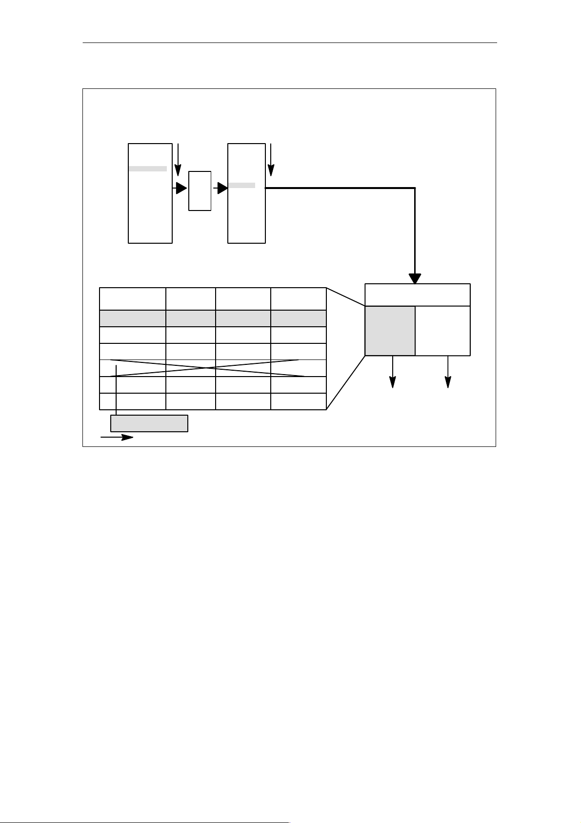
Validity, ID,
IDS
Fre-
quency
Condition
Action(s)
techn. cycles
Stored, preprocessed synchronized actions
Memory size: MD 28250: $MC_MM_NUM_SYNC_ELEMENTS
Part program
Program
preprocessing
Prepared
PP blocks
N5 block1
N10 block2
N15 ID=1
N20 block4
N25 block5
...
block1’
block2’
[ – ]
block4’
block5’
...
ID 1 WHENEVER $A_..< $A_.. M130
Main run
Movement of
axes, ...
Synchroni-
zed
action
processing
Sequence of synchronized action interpretation
SetpointsActions,
technology cycles
Deletion
Fig. 2-1 Schematic diagram illustrating processing of synchronized actions
Synchronized actions are checked in the interpolation cycle to determine
whether they contain actions to be activated. Action(s) are executed in synchro-
nism with path control if the preconditions programmed on the left of the ac-
tion(s) are fulfilled.
Within an interpolation cycle, modal synchronized action instructions are pro-
cessed in order of their ID number (i.e. block with ID number 1 before block with
ID number 2, etc.). Once the modal synchronized action instructions have been
executed, non-modal synchronized action instructions are processed in the or-
der in which they are programmed.
Processing of
synchronized
actions
Order of execution

03.04
Synchronized Actions (FBSY)
2.1 Components of synchronized actions
2-21
Siemens AG, 2004. All rights reserved
SINUMERIK 840D/840Di/810D Descr. of Functions Synchronized Actions (FBSY) – 03.04 Edition
2.1.1 Definition of motion-synchronous actions
Motion-synchronous actions can be defined in the following ways:
S In the part program
S Static synchronized actions in an asynchronous subprogram activated by
the PLC
2.1.2 Execution of synchronized actions
The actions programmed in motion-synchronous actions are executed if
S The synchronized action exists and has not been deselected with CAN-
CEL(ID) (see Subsection 2.5.1)
S The synchronized action is not disabled, i.e. no LOCK(ID) (see Subsection
2.5.1)
S Evaluation of the action is due as a result of the programmed frequency key-
word or
S The appropriate condition is fulfilled
For further details, please see the following subsections.
Defining programs
Conditions for
execution

03.04
2.1 Components of synchronized actions
Synchronized Actions (FBSY)
2-22
Siemens AG, 2004. All rights reserved
SINUMERIK 840D/840Di/810D Descr. of Functions Synchronized Actions (FBSY) – 03.04 Edition
2.1.3 List of possible actions
S Output of M, S and H auxiliary functions to the PLC
S Real-time variables can be set (written) to obtain the following functionality:
– Overlaid movement ($AA_OFF), option.
– Feedrate control ($AC_OVR, $AA_OVR),
disabling of a programmed axis motion
– ...
S Changes to SW cam positions and times (setting data) and alteration of
other setting data
S Modification of coefficients and limits from FCTDEF
S SYNFCT (polynomial evaluation)
S FTOC (online tool offsets)
S RDISABLE (read-in disable)
S STOPREOF (preprocessing stop cancellation)
S DELDTG (delete distance-to-go)
S Calculation of curve table values
S Axial feedrate from synchronized actions
S Axial frames
S Moving/positioning axes from synchronized actions
S Spindle motions from synchronized actions
S Actual-value setting from synchronized actions (Preset)
S Activation/deactivation of couplings and coupled motion
S Measurements from synchronized actions
S Setting and deletion of wait markers for channel synchronization
S Set alarm/error reactions
S Travel to fixed stop FXS (FXST, FXSW)
S Travel with limited torque FOC (FOCON/FOCOF)
S Extended stop and retract (Description of Functions M3)
S Reading and, if tagged accordingly, writing of system variables from the list
in Subsection 2.3.11.
These actions are described in detail in Section 2.4.
12.9712.9710.0012.9810.00

03.04
Synchronized Actions (FBSY)
2.2 Real-time evaluations and calculations
2-23
Siemens AG, 2004. All rights reserved
SINUMERIK 840D/840Di/810D Descr. of Functions Synchronized Actions (FBSY) – 03.04 Edition
2.2 Real-time evaluations and calculations
Calculations carried out in real time represent a subset of those calculations that
can be performed in the NC language. It is restricted to data types REAL, INT,
CHAR and BOOL.
Implicit type conversions, such as in the part program, do not take place. See
data type below.
The term “Real-time expression” refers below to all calculations that can be car-
ried out in the interpolation cycle. Real-time expressions are used in conditions
and in assignments to NC addresses and variables.
All real-time variables are evaluated (read) in the interpolation cycle and can be
written as part of an action.
Real-time variables are all variables that begin with:
$A... (main run variable) or
$V... (servo values).
So that they can be clearly identified, these variables can be programmed with
$$ in synchronized actions.
E.g. $AA_IM[X] or $$AA_IM[Y]: Actual value for X axis or Y axis in the machine
coordinate system.
Note
Setting data and machine data must be programmed with $$S... / $$M... if its
value changes during machining.
Only real-time variables of the same data type may be linked by a logic opera-
tion within the same expression. However, in order to process various types of
data, you can use the conversion routines provided for type matching (SW 5.2,
see conversion routines). In contrast to full expressions in the NC language,
calculations are performed in the data type of the real-time variables involved.
... DO $R10 = $AC_PARAM[0] ; permissible REAL, REAL
... DO $R10 = $AC_MARKER[0] ; not permissible: REAL, INT
The following examples of real-time evaluations were already available in SW
version 3.2 (they employ only real-time variables of this SW version):
On the left of the comparison, there is a comparison variable calculated in real
time and, on the right, an expression, which is none of the permitted real-time
processing variables that begin with $$.
WHEN $AA_IM[X] > $A_INA[1] DO M120
Restriction
Scope of
application
Real-time variables
Real-time variable
identifiers
Data type
Example 1 for
SW 3.2
01.00

03.04
2.2 Real-time evaluations and calculations
Synchronized Actions (FBSY)
2-24
Siemens AG, 2004. All rights reserved
SINUMERIK 840D/840Di/810D Descr. of Functions Synchronized Actions (FBSY) – 03.04 Edition
M120 is output during execution of the motion programmed in the following
block if the X axis actual value exceeds the value applied at analog input 1.
With this programming, the actual value is re-evaluated in every interpolation
cycle while the value of the analog input is generated at the instant of interpreta-
tion.
On the left of the comparison, there is a comparison variable calculated in real
time and, on the right, an expression, which is one of those permitted for the
synchronized action (beginning with $$).
WHEN $AA_IM[X] > $$A_INA[1] DO M120
The current actual value of the X axis is compared in the IPO cycle with analog
input 1 because an $$ variable is programmed on the right.
Both variables are compared to one another in the interpolation cycle.
$$ variables may also be programmed on the left of the comparison.
WHEN $$AA_IM[X] > $$A_INA[1] DO M120
Identical to example 2. The left-hand and right-hand sides are always compared
in real time.
The real-time variables available in synchronized actions are listed in Subsec-
tion 2.3.11. New system variables, which have been added in subsequent soft-
ware versions are indicated in the table.
S Machine and setting data
In the case of machine and setting data, $$S... or $$M... must be programmed
for online access. The access instruction to be evaluated during interpretation/
decoding must be preceded by a $ sign. Real-time variables that may legally be
accessed from synchronized actions are addressed preceded only by a $ sign.
There is no implicit type conversion from REAL to INT and vice versa for syn-
chronized actions. However, the user may explicitly call two conversion routines
RTOI( ) and ITOR( ) for type conversion. The functions can be called
S In the part program and
S From the synchronized action.
REAL ITOR( INT ) – Converting integer to real
The function converts the integer value transferred to a real value and returns
this value. The transferred variable is not changed.
Example:
$AC_MARKER[1] = 561
ID=1 WHEN TRUE DO $AC_PARAM[1] = ITOR( $AC_MARKER[1] )
INT RTOI( REAL ) – Converting from real to integer
Example 2 for
SW 3.2
Example 3 for
SW 3.2
Extensions in
SW 4
Conversion
routines (SW 5.2)
ITOR
RTOI
01.00

03.04
Synchronized Actions (FBSY)
2.2 Real-time evaluations and calculations
2-25
Siemens AG, 2004. All rights reserved
SINUMERIK 840D/840Di/810D Descr. of Functions Synchronized Actions (FBSY) – 03.04 Edition
The function RTOI() converts the Real value presented to a rounded INT value
and returns this integer value. If the value transferred lies outside the range that
can be unambiguously represented as an integer value, alarm 20145 “Motion-
synchronous action: Arithmetic error” is output and no conversion is performed.
The transferred variable is not changed.
Note
The function RTOI() does not produce an unambiguous result when inverted,
i.e. it is not possible to determine the original Real value from the value
returned as the decimal places are lost during conversion!
Example RTOI:
$AC_PARAM[1] = 561.4378
ID=1 WHEN TRUE DO $AC_MARKER[1] = RTOI( $AC_PARAM[1] )
; Result: 561
...
$AC_PARAM[1] = –63.867
ID=1 WHEN TRUE DO $AC_MARKER[1] = RTOI( $AC_PARAM[1] )
; Result:–64
...
$AC_MARKER[1]= 10 $AC_PARAM[1] = –6386798797.29
ID=1 WHEN TRUE DO $AC_MARKER[1] = RTOI( $AC_PARAM[1] )
;Result: Alarm 20145
;$AC_MARKER[1] = 10 (unchanged due to alarm)
In SW 6.4 and later, variables of various data types can be assigned to one
another in synchronized actions without having to call the RTOI or ITOR func-
tion, e.g. REAL to INT and vice versa.
If values outside of the interval [INT_MIN, INT_MAX] would result from the con-
version from REAL to INTEGER, alarm 20145 “Motion-synchronous action:
Arithmetic error” is output and no conversion is performed.
Examples:
Previously
$AC_MARKER[1] = 561
ID=1 WHEN TRUE DO $AC_PARAM[1] = ITOR( $AC_MARKER[1] )
In software version 6.4 and later
$AC_MARKER[1] = 561
ID=1 WHEN TRUE DO $AC_PARAM[1] = $AC_MARKER[1]
Previously
$AC_PARAM[1] = 561.4378
ID=1 WHEN TRUE DO $AC_MARKER[1] = RTOI( $AC_PARAM[1] ) ; 561
In software version 6.4 and later
$AC_PARAM[1] = 561.4378
ID=1 WHEN TRUE DO $AC_MARKER[1] = $AC_PARAM[1] : 561
Implicit type
conversion
(SW 6.4)
01.0003.02

03.04
2.2 Real-time evaluations and calculations
Synchronized Actions (FBSY)
2-26
Siemens AG, 2004. All rights reserved
SINUMERIK 840D/840Di/810D Descr. of Functions Synchronized Actions (FBSY) – 03.04 Edition
Real-time variables of the REAL and INT type can be linked logically by the fol-
lowing basic arithmetic operations:
– Addition
– Subtraction
– Multiplication
– Division
– Integer division
– Modulo division
Only variables of the same type may be linked by these operations.
Expressions from basic arithmetic operations can be bracketed and nested.
See priorities for operators on the next page.
The following relational operators may be used:
== Equal to
<> Not equal to
< Less than
> Greater than
<= Less than or equal to
>= Greater than or equal to
The following Boolean operators may be used:
NOT NOT,
AND AND,
OR OR,
XOR Exclusive OR
The following bit operators may be used:
B_OR Bit-serial OR
B_AND Bit-serial AND
B_XOR Bit-serial exclusive OR
B_NOT Bit-serial negation
Operands are variables and constants of the INT type.
Basic arithmetic
operations
Expressions
Comparisons
Boolean operators
Bit operators

03.04
Synchronized Actions (FBSY)
2.2 Real-time evaluations and calculations
2-27
Siemens AG, 2004. All rights reserved
SINUMERIK 840D/840Di/810D Descr. of Functions Synchronized Actions (FBSY) – 03.04 Edition
In order to produce the desired logical result in multiple expressions, the follow-
ing operator priorities should be observed in calculations and conditions:
1. NOT, B_NOT Negation, bit-serial negation
2. *, /, DIV, MOD Multiplication, division
3. +, – Addition, subtraction
4. B_AND Bit-serial AND
5. B_XOR Bit-serial exclusive OR
6. B_OR Bit-serial OR
7. AND AND
8. XOR Exclusive OR
9. OR OR
10. Not used
11. Relational operators
== Equal to
<> Not equal to
> Greater than
< Less than
>= Greater than or equal to
<= Less than or equal to
and parentheses should be used where necessary. The logic operation result
for a condition must be a BOOL data type.
Example of a multiple expression:
WHEN ($AA_IM[X] > VALUE) AND ($AA_IM[Y] > VALUE1) DO ...
A real-time variable of the REAL type can be used to create function values
sine, cosine, etc.
The following functions are possible:
SIN, COS, ABS, ASIN, ACOS, TAN, ATAN2,
TRUNC, ROUND, LN, EXP, ATAN, POT, SQRT,
CTAB, CTABINV
Example:
... DO $AC_PARAM[3]=COS($AA_IM[X])
For a description of how to use these functions, please see:
References: /PG/, Programming Guide
/PGA/, Programming Guide Advanced
The index of a real-time field variable can in turn be a real-time variable.
Example:
WHEN ... DO $AC_PARAM[ $AC_MARKER[1] ] = 3
The current value of the index $AC_MARKER[1] is evaluated in each interpola-
tion cycle.
Priority of
operators
Functions
Indexing

03.04
2.2 Real-time evaluations and calculations
Synchronized Actions (FBSY)
2-28
Siemens AG, 2004. All rights reserved
SINUMERIK 840D/840Di/810D Descr. of Functions Synchronized Actions (FBSY) – 03.04 Edition
Restrictions:
– It is not permissible to nest indices with real-time variables.
– A real-time index cannot be generated by a variable that is not gener-
ated itself in real time. The following programming would lead to errors:
$AC_PARAM[1]=$P_EP[$AC_MARKER[0]]

03.04
Synchronized Actions (FBSY)
2.3 Special real-time variables for synchronized actions
2-29
Siemens AG, 2004. All rights reserved
SINUMERIK 840D/840Di/810D Descr. of Functions Synchronized Actions (FBSY) – 03.04 Edition
2.3 Special real-time variables for synchronized actions
A complete list of system variables that may be addressed in synchronized
actions can be found in Subsection 2.3.11. The characteristics of a few special
real-time variables are described below:
S Marker/counter variables
– Channel-specific markers
S Timers
S Synchronized action parameters
S R parameters
S Machine and setting data
S FIFO variables (circulating memory)
Special real-time variables, i.e. timers, R parameters, machine and setting data
and FIFO variables are available in SW 4 and later.
2.3.1 Marker/counter variables
The $AC_MARKER[n] variable serves as a marker or counter in the INTEGER
data type.
n: Number of marker: 0-n
The number of markers per channel is set via machine data
MD 28256: NUM_AC_MARKER.
Markers exist once in each channel under the same name. They are stored in
the dynamic memory and reset to 0 on POWER ON, NC RESET and End of
Program, ensuring identical start conditions for every program run.
Marker variables can be read and written in synchronized actions.
In software version 6.3 and later, it is possible to select the memory location for
$AC_MARKER[n] between DRAM and SRAM using
MD 28257: MM_BUFFERED_AC_MARKER.
0: Dynamic memory DRAM, (default)
1: Static memory SRAM
A maximum value of 2000 can be assigned to machine data 28256:
NUM_AC_MARKER. One element requires 4 bytes. You must ensure that suffi-
cient memory of the correct type is available.
Markers saved in SRAM can be included in the data backup. See Subsec-
tion 2.3.7
SW 4
Channel-specific
markers
Also available in
SW 6.3 and later
06.01

03.04
2.3 Special real-time variables for synchronized actions
Synchronized Actions (FBSY)
2-30
Siemens AG, 2004. All rights reserved
SINUMERIK 840D/840Di/810D Descr. of Functions Synchronized Actions (FBSY) – 03.04 Edition
2.3.2 Timers
System variable $AC_TIMER[n] permits actions to be started after defined wait-
ing times.
n: Number of timer variable
Unit: Seconds
Data type: REAL
The number of available timer variables is programmed in machine data
MD 28258: MM_NUM_AC_TIMER.
Incrementation of a timer variable is started by means of value assignment:
$AC_TIMER[n]=value
n: Number of timer variable
Value: Start value (normally 0)
Incrementation of a timer variable can be stopped by assigning a negative
value:
$AC_TIMER[n]=–1
The current timer value can be read whether the timer variable is running or has
been stopped. Once a timer variable has been stopped by assigning –1, the
current timer value remains stored and can be read.
Output of an actual value via analog output 500 ms after detection of a digital
input:
WHEN $A_IN[1]==1 DO $AC_TIMER[1]=0 ;Reset and start timer
WHEN $AC_TIMER[1]>=0.5 DO $A_OUTA[3]=$AA_IM[X] $AC_TIMER[1]=–1
Setting timers
Stopping timers
Reading timers
Example
Loading...