


Installation and Start-Up Guide 11/2002 Edition
& simodrive
SINUMERIK 840D SIMODRIVE 611 digital


SINUMERIK 840D SIMODRIVE 611 digital
Installation and Start-Up Guide
Valid for |
|
|
Control |
Software version |
|
SINUMERIK 840D |
|
6 |
SINUMERIK 840DE (export version) |
6 |
|
SINUMERIK 840D powerline |
6 |
|
SINUMERIK 840DE powerline |
6 |
|
Drive |
|
|
SIMODRIVE 611 digital |
|
6 |
11.2002 Edition
General Preparations
Configuration
Settings, MPI / OPI
EMC / ESD Measures
Power ON and Booting
Parameterization of
Control System
PLC Start-Up
Alarm and Message Texts
Axis and Spindle Dry Run
Drive Optimization with Start-Up Tool
Data Backup
Software and Hardware
Replacement
HMI/MMC
Miscellaneous
Abbreviations
References
Index
1
2
3
4
5
6
7
8
9
10
11
12
13
14
A
B
3ls SINUMERIK Documentation
Printing history
Brief details of this edition and previous editions are listed below.
The status of each edition is shown by the code in the “Remarks” column.
Status code in the “Remarks” column:
A . . . . . New documentation.
B . . . . . Unrevised reprint with new order no. C . . . . . Revised edition with new status.
If factual changes have been made on the page in relation to the same software version, this is indicated by a new edition coding in the header on that page.
Edition |
Order No. |
Remarks |
06.94 |
6FC5 297-0AB10-0BP0 |
A |
08.94 |
6FC5 297-0AB10-0BP1 |
C |
02.95 |
6FC5 297-2AB10-0BP0 |
C |
04.95 |
6FC5 297-2AB10-0BP1 |
C |
09.95 |
6FC5 297-3AB10-0BP0 |
C |
03.96 |
6FC5 297-3AB10-0BP1 |
C |
08.97 |
6FC5 297-4AB10-0BP0 |
C |
12.97 |
6FC5 297-4AB10-0BP1 |
C |
12.98 |
6FC5 297-5AB10-0BP0 |
C |
08.99 |
6FC5 297-5AB10-0BP1 |
C |
04.00 |
6FC5 297-5AB10-0BP2 |
C |
10.00 |
6FC5 297-6AB10-0BP0 |
C |
09.01 |
6FC5 297-6AB10-0BP1 |
C |
11.02 |
6FC5 297-6AB10-0BP2 |
C |
This book is part of the documentation on CD-ROM (DOCONCD)
Edition Order No. Remarks
C
Trademarks
SIMATICr, SIMATIC HMIr, SIMATIC NETr, SIROTECr, SINUMERIKr and SIMODRIVEr are trademarks of Siemens. Other product names used in this documentation may be trademarks which, if used by third parties, could infringe the rights of their owners.
Further information is available on the Internet under: http://www.ad.siemens.de/sinumerik
This publication was produced with Interleaf V7.
The reproduction, transmission or use of this document or its contents is not permitted without express written authority. Offenders will be liable for damages. All rights, including those created by patent grant or registration of a utility model or design, are reserved.
Other functions not described in this documentation might be executable in the control. However, no claim can be made regarding the availability of these functions when the equipment is first supplied or for service cases.
We have checked that the contents of this document correspond to the hardware and software described. Nonetheless, differences might exist and therefore we cannot guarantee that they are completely identical. The information contained in this document is, however, reviewed regularly and any necessary changes will be included in the next edition. We welcome suggestions for improvement.
Siemens AG, 1994–2002. All rights reserved |
Subject to changes without prior notice |
|
|
Order No. 6FC5 297-6AB10-0BP2 |
Siemens Aktiengesellschaft |
Printed in Germany |
|
10.00 |
SINUMERIK 840D Installation & Start-Up Guide |
Preface
PREFACE
Organization of |
The SINUMERIK documentation is organized on three separate levels: |
|||
the documentation |
S |
General Documentation |
|
|
|
|
|
||
|
S |
User Documentation |
|
|
|
S |
Manufacturer/Service Documentation. |
||
Target group |
This document is intended for manufacturers of machine tools incorporating |
|||
|
SINUMERIK 840D and SIMODRIVE 611D. |
|||
Hotline |
If you have any questions about the control, please contact the hotline: |
|||
|
A&D Technical Support |
Phone: ++49-180-5050-222 |
||
|
|
|
Fax: |
++49-180-5050-223 |
|
|
|
Email: |
adsupport@siemens.com |
|
Please send any questions about the documentation (suggestions for improve- |
|||
|
ment, corrections) to the following fax number or email address: |
|||
|
|
|
Fax: |
++49-9131-98-2176 |
|
|
|
Email: |
motioncontrol.docu@erlf.siemens.de |
Fax form: see reply form at the end of the manual.
Internet address http://www.ad.siemens.de/sinumerik
SINUMERIK
SINUMERIK 840D Improved performance variants
powerline
S SINUMERIK 840D powerline and
S SINUMERIK 840DE powerline
will be available from 09.2001 onwards. For a list of available powerline modules, please refer to Section 1.1 of the Hardware Description /PHD/.
SINUMERIK 810D Improved performance variants
powerline
S SINUMERIK 810D powerline and
S SINUMERIK 810DE powerline
will be available from 12.2001 onwards. For a list of available powerline modules, please refer to Section 1.1 of the Hardware Description /PHC/.
Siemens AG, 2002. All rights reserved |
v |
SINUMERIK 840D Installation and Start-Up Guide (IAD) – 11.02 Edition |

SINUMERIK 840D Installation & Start-Up Guide |
10.00 |
|||
Preface |
|
|
|
|
Objective |
The installation and start-up guide provides the information required for start-up |
|||
|
and servicing. |
|
|
|
Standard scope |
The Guide explains the control system design and the interfaces of the |
|
||
|
individual components. It describes the procedures required to start up |
|
||
|
SINUMERIK 840D with SIMODRIVE 611D, and lists all data, signals and PLC |
|||
|
modules. |
|
|
|
|
Informationen on individual functions, function assignments, performance data |
|||
|
of the individual components can be found in special separate documents (such |
|||
|
as manuals, descriptions of functions). |
|
||
|
Separate Reference Manuals are available for user-oriented activities such as |
|||
|
creating parts programs and operating the control system. |
|
||
|
There are finally separate Reference Manuals describing how the machine |
|||
|
manufacturer is to perform certain procedures, such as configure, install and |
|||
|
program the PLC. |
|
|
|
Finding |
To help you access the information you need, this publication includes a table of |
|||
information |
contens and list of figures and tables, but also provides you with the following |
|||
|
additional information available in the appendix: |
|
||
|
1. |
List of Abbreviations |
|
|
|
2. |
List of References |
|
|
|
3. |
Index. |
|
|
|
For a list and description of alarms used in SINUMERIK 840D please see the |
|||
|
References: |
/DA/, Diagnostics Guide |
|
|
Further information for installation and start-up and troubleshooting is provided in the
References: /FB/, D1, “Diagnostics Tools”
Note |
The following notes appear in this document to draw your attention to informa- |
|
tion relevant to the subject in hand: |
Note
This symbol always appears in this documentation when important information is being conveyed.
Important
!This symbol always appears in this documentation when important information is being conveyed.
vi |
Siemens AG, 2002. All rights reserved |
SINUMERIK 840D Installation and Start-Up Guide (IAD) – 11.02 Edition |

10.00 |
SINUMERIK 840D Installation & Start-Up Guide |
10.00 |
Preface
Order data option
This symbol appears in the documentation to draw your attention to an ordering data option. The described function will be performed only if the control contains the mentioned option.
Warnings |
The following warnings with varying degrees of severity appear in this docu- |
|
ment. |
Danger
!Indicates an imminently hazardous situation which, if not avoided, will result in death or serious injury or in substantial property damage.
Caution
!Used with the safety alert symbol indicates a potentially hazardous situation which, if not avoided, may result in minor or moderate injury or in property damage.
Warning
!Indicates a potentially hazardous situation which, if not avoided, could result in death or serious injury or in substantial property damage.
Caution
Used without safety alert symbol indicates a potentially hazardous situation which, if not avoided, may result in property damage.
Notice
Used without the safety alert symbol indicates a potential situation which, if not avoided, may result in an undesirable result or state.
Siemens AG, 2002. All rights reserved |
vii |
SINUMERIK 840D Installation and Start-Up Guide (IAD) – 11.02 Edition |
SINUMERIK 840D Installation & Start-Up Guide |
10.00 |
Preface |
|
Technical Information
Trademarks |
IBM is a registered trademark by International Business Corporation. |
|
MS-DOS and WINDOWST are registered trademarks of the Microsoft |
|
Corporation. |
Notations |
The following notations and abbreviations appear in this documentation: |
|
S PLC interface signals –> IS “signal name” (signal data) |
|
Examples: |
|
– IS “MMC CPU1 ready” (DB10, DBX108.2), i.e. the signal is stored in data |
|
block 10, data byte 108, bit 2. |
|
– IS “Feed/spindle override” (DB31–48, DBB0) i.e. the signals are stored |
|
per axis / per spindle in data blocks 31 to 48, data block byte 0. |
|
S Machine data –> MD: MD_NAME (German name) |
|
S Setting data –> SD: SD_NAME (German name) |
|
S The symbol “8” means “corresponds to”. |
Effectiveness of |
Whenever you change data (e.g. machine data), please also note their activa- |
changes |
tion (e.g. after power ON or immediately). The time of activation is therefore al- |
|
ways indicated. |
viii |
Siemens AG, 2002. All rights reserved |
SINUMERIK 840D Installation and Start-Up Guide (IAD) – 11.02 Edition |
Contents
1 |
General Preparations . . . . . . . . . . . . . . . . . . . . . . . . . . . . . . . . . . . . . . . . . . . . . . . . |
1-15 |
|
|
1.1 |
Preconditions . . . . . . . . . . . . . . . . . . . . . . . . . . . . . . . . . . . . . . . . . . . . . . . |
1-15 |
|
1.2 |
Standard/export version . . . . . . . . . . . . . . . . . . . . . . . . . . . . . . . . . . . . . . |
1-16 |
2 |
Configuration . . . . . . . . . . . . . . . . . . . . . . . . . . . . . . . . . . . . . . . . . . . . . . . . . . . . . . . |
2-19 |
|
|
2.1 |
Mechanical configuration . . . . . . . . . . . . . . . . . . . . . . . . . . . . . . . . . . . . . |
2-20 |
|
2.1.1 |
Overview . . . . . . . . . . . . . . . . . . . . . . . . . . . . . . . . . . . . . . . . . . . . . . . . . . . |
2-20 |
|
2.1.2 |
Mains infeed module . . . . . . . . . . . . . . . . . . . . . . . . . . . . . . . . . . . . . . . . . |
2-21 |
|
2.1.3 |
NCU . . . . . . . . . . . . . . . . . . . . . . . . . . . . . . . . . . . . . . . . . . . . . . . . . . . . . . . |
2-22 |
|
2.1.4 |
General configuration of SINUMERIK 840D . . . . . . . . . . . . . . . . . . . . . |
2-23 |
|
2.2 |
Electrical configuration . . . . . . . . . . . . . . . . . . . . . . . . . . . . . . . . . . . . . . . |
2-23 |
|
2.2.1 |
Component connections . . . . . . . . . . . . . . . . . . . . . . . . . . . . . . . . . . . . . . |
2-23 |
|
2.2.2 |
Connection of mains infeed module (OI, I/RF) . . . . . . . . . . . . . . . . . . . |
2-25 |
|
2.2.3 |
Motor connection . . . . . . . . . . . . . . . . . . . . . . . . . . . . . . . . . . . . . . . . . . . . |
2-28 |
|
2.2.4 |
Encoder connection . . . . . . . . . . . . . . . . . . . . . . . . . . . . . . . . . . . . . . . . . . |
2-29 |
|
2.2.5 |
PCU 20 and PCU 50 connection . . . . . . . . . . . . . . . . . . . . . . . . . . . . . . . |
2-30 |
|
2.2.6 |
Configuration of components for digitizing . . . . . . . . . . . . . . . . . . . . . . . |
2-32 |
3 |
Settings, MPI / OPI . . . . . . . . . . . . . . . . . . . . . . . . . . . . . . . . . . . . . . . . . . . . . . . . . . . |
3-35 |
|
|
3.1 |
MPI/OPI, network rules . . . . . . . . . . . . . . . . . . . . . . . . . . . . . . . . . . . . . . . |
3-36 |
|
3.2 |
Standard configuration . . . . . . . . . . . . . . . . . . . . . . . . . . . . . . . . . . . . . . . |
3-38 |
|
3.2.1 |
Standard configuration for SW 3.1 and lower . . . . . . . . . . . . . . . . . . . . |
3-38 |
|
3.2.2 |
Standard configuration for SW 3.2 and higher . . . . . . . . . . . . . . . . . . . |
3-40 |
3.3Connection of a 2nd MCP/customer operator panel front and/or 1 HHU
|
(SW 3.1 and lower) . . . . . . . . . . . . . . . . . . . . . . . . . . . . . . . . . . . . . . . . . . |
3-43 |
3.3.1 |
Connection to OPI bus . . . . . . . . . . . . . . . . . . . . . . . . . . . . . . . . . . . . . . . |
3-44 |
3.3.2 |
Connection to MPI bus . . . . . . . . . . . . . . . . . . . . . . . . . . . . . . . . . . . . . . . |
3-45 |
3.3.3 |
Example of a configuration of MCP and HHU via OPI . . . . . . . . . . . . . |
3-46 |
3.3.4 |
Example of a configuration of HHU via MPI . . . . . . . . . . . . . . . . . . . . . . |
3-47 |
3.4 |
Handheld unit . . . . . . . . . . . . . . . . . . . . . . . . . . . . . . . . . . . . . . . . . . . . . . . |
3-52 |
3.4.1 |
Settings on the HHU up to 3.x . . . . . . . . . . . . . . . . . . . . . . . . . . . . . . . . . |
3-52 |
3.4.2 |
Settings on the HHU for SW 4.x and higher . . . . . . . . . . . . . . . . . . . . . |
3-53 |
3.4.3 |
Configuring the HHU, setting interface parameters . . . . . . . . . . . . . . . |
3-53 |
3.4.4 |
Example: Connecting the HHU to the SINUMERIK 840D . . . . . . . . . . |
3-55 |
3.5 |
Handheld programming unit . . . . . . . . . . . . . . . . . . . . . . . . . . . . . . . . . . . |
3-56 |
3.5.1 |
Interface signals of the HPU . . . . . . . . . . . . . . . . . . . . . . . . . . . . . . . . . . . |
3-57 |
3.5.2 |
Standard configuration of the HPU (without MCP) . . . . . . . . . . . . . . . . |
3-58 |
3.5.3 |
Deviations from the standard HPU configuration (SW 3.1 and lower) |
3-59 |
3.6 |
Machine control panel (MCP) . . . . . . . . . . . . . . . . . . . . . . . . . . . . . . . . . . |
3-66 |
3.7 |
Customer operator panel front . . . . . . . . . . . . . . . . . . . . . . . . . . . . . . . . . |
3-68 |
Siemens AG, 2002. All rights reserved |
ix |
SINUMERIK 840D Installation and Start-Up Guide (IAD) – 11.02 Edition |
SINUMERIK 840D Installation & Start-Up Guide |
11.02 |
|
||
10.00 |
||||
Contents |
|
|
|
|
|
3.8 |
2nd machine control panel . . . . . . . . . . . . . . . . . . . . . . . . . . . . . . . . . . . . |
3-69 |
|
|
3.9 |
MMC 100/MMC 103 operator panel front . . . . . . . . . . . . . . . . . . . . . . . . |
3-69 |
|
|
3.9.1 |
Settings on the MMC . . . . . . . . . . . . . . . . . . . . . . . . . . . . . . . . . . . . . . . . . |
3-69 |
|
|
3.9.2 |
Language default . . . . . . . . . . . . . . . . . . . . . . . . . . . . . . . . . . . . . . . . . . . . |
3-70 |
|
4 |
EMC / ESD Measures . . . . . . . . . . . . . . . . . . . . . . . . . . . . . . . . . . . . . . . . . . . . . . . . |
4-73 |
||
|
4.1 |
Measures to suppress interference . . . . . . . . . . . . . . . . . . . . . . . . . . . . . |
4-73 |
|
|
4.2 |
Measures to protect ESD . . . . . . . . . . . . . . . . . . . . . . . . . . . . . . . . . . . . . |
4-74 |
|
|
4.3 |
Cooling . . . . . . . . . . . . . . . . . . . . . . . . . . . . . . . . . . . . . . . . . . . . . . . . . . . . . |
4-74 |
|
5 |
Power ON and Booting . . . . . . . . . . . . . . . . . . . . . . . . . . . . . . . . . . . . . . . . . . . . . . |
5-75 |
||
|
5.1 |
Start-up sequence . . . . . . . . . . . . . . . . . . . . . . . . . . . . . . . . . . . . . . . . . . . |
5-75 |
|
|
5.2 |
Power ON and Booting . . . . . . . . . . . . . . . . . . . . . . . . . . . . . . . . . . . . . . . |
5-76 |
|
|
5.2.1 |
Power ON . . . . . . . . . . . . . . . . . . . . . . . . . . . . . . . . . . . . . . . . . . . . . . . . . . |
5-77 |
|
|
5.2.2 |
Booting . . . . . . . . . . . . . . . . . . . . . . . . . . . . . . . . . . . . . . . . . . . . . . . . . . . . . |
5-77 |
|
|
5.2.3 |
Boot PCU 20 / PCU 50 . . . . . . . . . . . . . . . . . . . . . . . . . . . . . . . . . . . . . . . |
5-80 |
|
|
5.2.4 |
Boot MMC . . . . . . . . . . . . . . . . . . . . . . . . . . . . . . . . . . . . . . . . . . . . . . . . . . |
5-81 |
|
|
5.2.5 |
Error during control boot (NC) . . . . . . . . . . . . . . . . . . . . . . . . . . . . . . . . . |
5-82 |
|
|
5.2.6 |
Machine control panel (MCP) boot . . . . . . . . . . . . . . . . . . . . . . . . . . . . . |
5-83 |
|
|
5.2.7 |
Drive system boot . . . . . . . . . . . . . . . . . . . . . . . . . . . . . . . . . . . . . . . . . . . |
5-83 |
|
|
5.2.8 |
MMC 103 BIOS setup . . . . . . . . . . . . . . . . . . . . . . . . . . . . . . . . . . . . . . . . |
5-84 |
|
6 |
Parameterization of Control System . . . . . . . . . . . . . . . . . . . . . . . . . . . . . . . . . . . |
6-85 |
||
|
6.1 |
Machine and setting data . . . . . . . . . . . . . . . . . . . . . . . . . . . . . . . . . . . . . |
6-87 |
|
|
6.2 |
Handling machine and setting data . . . . . . . . . . . . . . . . . . . . . . . . . . . . . |
6-89 |
|
|
6.3 |
Protection level concept . . . . . . . . . . . . . . . . . . . . . . . . . . . . . . . . . . . . . . |
6-90 |
|
|
6.4 |
Machine data masking filter (SW 4.2 and higher) . . . . . . . . . . . . . . . . . |
6-92 |
|
|
6.4.1 |
Function . . . . . . . . . . . . . . . . . . . . . . . . . . . . . . . . . . . . . . . . . . . . . . . . . . . . |
6-92 |
|
|
6.4.2 |
Selecting and setting the machine data masking filters . . . . . . . . . . . . |
6-92 |
|
|
6.4.3 |
Saving the filter settings . . . . . . . . . . . . . . . . . . . . . . . . . . . . . . . . . . . . . . |
6-95 |
|
|
6.5 |
Example of a start-up design concept . . . . . . . . . . . . . . . . . . . . . . . . . . . |
6-96 |
|
|
6.6 |
System data . . . . . . . . . . . . . . . . . . . . . . . . . . . . . . . . . . . . . . . . . . . . . . . . |
6-99 |
|
|
6.6.1 |
Basic settings . . . . . . . . . . . . . . . . . . . . . . . . . . . . . . . . . . . . . . . . . . . . . . . |
6-99 |
|
|
6.7 |
Memory configuration . . . . . . . . . . . . . . . . . . . . . . . . . . . . . . . . . . . . . . . . |
6-102 |
|
|
6.7.1 |
Dynamic RAM memory . . . . . . . . . . . . . . . . . . . . . . . . . . . . . . . . . . . . . . . |
6-103 |
|
|
6.7.2 |
Static RAM memory . . . . . . . . . . . . . . . . . . . . . . . . . . . . . . . . . . . . . . . . . . |
6-104 |
|
|
6.8 |
Scaling machine data . . . . . . . . . . . . . . . . . . . . . . . . . . . . . . . . . . . . . . . . |
6-106 |
|
|
6.9 |
Axes and spindles . . . . . . . . . . . . . . . . . . . . . . . . . . . . . . . . . . . . . . . . . . . |
6-108 |
|
|
6.9.1 |
Description of the axis configuration . . . . . . . . . . . . . . . . . . . . . . . . . . . . |
6-108 |
|
|
6.9.2 |
Drive configuration (FDD, SLM, MSD) . . . . . . . . . . . . . . . . . . . . . . . . . . |
6-112 |
|
|
6.9.3 |
Setting the axis-specific setpoint/actual value parameters . . . . . . . . . |
6-115 |
|
|
6.9.4 |
Drive parameterization (FDD, MSD) . . . . . . . . . . . . . . . . . . . . . . . . . . . . |
6-117 |
|
|
6.9.5 |
Parameterization of incremental measuring systems . . . . . . . . . . . . . . |
6-119 |
|
|
6.9.6 |
Parameterization of absolute measuring systems (EnDat interface) . |
6-122 |
|
|
6.9.7 |
Overview of drive optimization parameters . . . . . . . . . . . . . . . . . . . . . . |
6-125 |
|
|
6.9.8 |
Axis data . . . . . . . . . . . . . . . . . . . . . . . . . . . . . . . . . . . . . . . . . . . . . . . . . . . |
6-128 |
|
|
6.9.9 |
Velocity matching (axis) . . . . . . . . . . . . . . . . . . . . . . . . . . . . . . . . . . . . . . |
6-130 |
|
x |
Siemens AG, 2002. All rights reserved |
SINUMERIK 840D Installation and Start-Up Guide (IAD) – 11.02 Edition |
11.02 |
|
SINUMERIK 840D Installation & Start-Up Guide |
|
|
10.00 |
|
|||
|
|
|
Contents |
|
|
6.9.10 |
Position controller data (axis) . . . . . . . . . . . . . . . . . . . . . . . . . . . . . . . . . . |
6-131 |
|
|
6.9.11 |
Monitoring functions (axis) . . . . . . . . . . . . . . . . . . . . . . . . . . . . . . . . . . . . |
6-136 |
|
|
6.9.12 |
Reference point approach (axis) . . . . . . . . . . . . . . . . . . . . . . . . . . . . . . . |
6-141 |
|
|
6.9.13 |
Spindle data . . . . . . . . . . . . . . . . . . . . . . . . . . . . . . . . . . . . . . . . . . . . . . . . |
6-143 |
|
|
6.9.14 |
Spindle configuration . . . . . . . . . . . . . . . . . . . . . . . . . . . . . . . . . . . . . . . . . |
6-145 |
|
|
6.9.15 |
Encoder matching (spindle) . . . . . . . . . . . . . . . . . . . . . . . . . . . . . . . . . . . |
6-145 |
|
|
6.9.16 |
Speeds and setpoint adjustment for spindle . . . . . . . . . . . . . . . . . . . . . |
6-147 |
|
|
6.9.17 |
Spindle positioning . . . . . . . . . . . . . . . . . . . . . . . . . . . . . . . . . . . . . . . . . . . |
6-148 |
|
|
6.9.18 |
Spindle synchronization . . . . . . . . . . . . . . . . . . . . . . . . . . . . . . . . . . . . . . |
6-149 |
|
|
6.9.19 |
Spindle monitoring . . . . . . . . . . . . . . . . . . . . . . . . . . . . . . . . . . . . . . . . . . . |
6-151 |
|
|
6.9.20 |
Example: Start-up of NCK I/O devices . . . . . . . . . . . . . . . . . . . . . . . . . . |
6-153 |
|
|
6.10 |
Linear motors (1FN1 and 1FN3 motors) . . . . . . . . . . . . . . . . . . . . . . . . . |
6-155 |
|
|
6.10.1 |
General information about starting up linear motors . . . . . . . . . . . . . . . |
6-155 |
|
|
6.10.2 |
Start-up: Linear motor with one primary part . . . . . . . . . . . . . . . . . . . . . |
6-157 |
|
|
6.10.3 |
Start-up: Linear motors with two identical primary parts . . . . . . . . . . . |
6-168 |
|
|
6.10.4 |
Mechanical components . . . . . . . . . . . . . . . . . . . . . . . . . . . . . . . . . . . . . . |
6-170 |
|
|
6.10.5 |
Temperature sensors for 1FN1 and 1FN3 motors . . . . . . . . . . . . . . . . |
6-171 |
|
|
6.10.6 |
Measuring system . . . . . . . . . . . . . . . . . . . . . . . . . . . . . . . . . . . . . . . . . . . |
6-174 |
|
|
6.10.7 |
Parallel connection of linear motors . . . . . . . . . . . . . . . . . . . . . . . . . . . . |
6-177 |
|
|
6.10.8 |
Test measurements on linear motor . . . . . . . . . . . . . . . . . . . . . . . . . . . . |
6-179 |
|
|
6.11 |
AM / V/F function . . . . . . . . . . . . . . . . . . . . . . . . . . . . . . . . . . . . . . . . . . . . |
6-181 |
|
|
6.12 |
System settings for boot, RESET and parts program start . . . . . . . . . |
6-182 |
|
7 |
PLC Start-Up . . . . . . . . . . . . . . . . . . . . . . . . . . . . . . . . . . . . . . . . . . . . . . . . . . . . . . . . |
7-185 |
||
|
7.1 |
PLC start-up . . . . . . . . . . . . . . . . . . . . . . . . . . . . . . . . . . . . . . . . . . . . . . . . |
7-185 |
|
|
7.2 |
Overview of organization blocks, function blocks and DBs . . . . . . . . . |
7-188 |
|
8 |
Alarm and Message Texts . . . . . . . . . . . . . . . . . . . . . . . . . . . . . . . . . . . . . . . . . . . . |
8-189 |
||
|
8.1 |
Alarm and message texts . . . . . . . . . . . . . . . . . . . . . . . . . . . . . . . . . . . . . |
8-190 |
|
|
8.1.1 |
Alarm text files for MMC 100 . . . . . . . . . . . . . . . . . . . . . . . . . . . . . . . . . . |
8-190 |
|
|
8.1.2 |
Alarm text files for MMC 102/103 . . . . . . . . . . . . . . . . . . . . . . . . . . . . . . |
8-192 |
|
|
8.1.3 |
Alarm text files for HPU . . . . . . . . . . . . . . . . . . . . . . . . . . . . . . . . . . . . . . . |
8-194 |
|
|
8.1.4 |
Syntax for alarm text files . . . . . . . . . . . . . . . . . . . . . . . . . . . . . . . . . . . . . |
8-196 |
|
|
8.1.5 |
Properties of alarm list . . . . . . . . . . . . . . . . . . . . . . . . . . . . . . . . . . . . . . . . |
8-199 |
|
9 |
Axis and Spindle Dry Run . . . . . . . . . . . . . . . . . . . . . . . . . . . . . . . . . . . . . . . . . . . . |
9-201 |
||
|
9.1 |
Preconditions . . . . . . . . . . . . . . . . . . . . . . . . . . . . . . . . . . . . . . . . . . . . . . . |
9-201 |
|
|
9.2 |
Axis test run . . . . . . . . . . . . . . . . . . . . . . . . . . . . . . . . . . . . . . . . . . . . . . . . |
9-203 |
|
|
9.3 |
Testing the spindle . . . . . . . . . . . . . . . . . . . . . . . . . . . . . . . . . . . . . . . . . . . |
9-205 |
|
10 |
Drive Optimization with Start-Up Tool . . . . . . . . . . . . . . . . . . . . . . . . . . . . . . . . . |
10-207 |
||
|
10.1 |
Instructions for use . . . . . . . . . . . . . . . . . . . . . . . . . . . . . . . . . . . . . . . . . . . |
10-208 |
|
|
10.1.1 |
System requirements . . . . . . . . . . . . . . . . . . . . . . . . . . . . . . . . . . . . . . . . . |
10-209 |
|
|
10.1.2 |
Installation . . . . . . . . . . . . . . . . . . . . . . . . . . . . . . . . . . . . . . . . . . . . . . . . . . |
10-209 |
|
|
10.1.3 |
Starting the program . . . . . . . . . . . . . . . . . . . . . . . . . . . . . . . . . . . . . . . . . |
10-210 |
|
|
10.1.4 |
Terminating the program . . . . . . . . . . . . . . . . . . . . . . . . . . . . . . . . . . . . . . |
10-210 |
|
|
10.2 |
Measuring functions . . . . . . . . . . . . . . . . . . . . . . . . . . . . . . . . . . . . . . . . . . |
10-211 |
|
|
10.3 |
Interface signals: Drive test travel request and travel enable . . . . . . . |
10-213 |
|
|
10.4 |
Aborting measuring functions . . . . . . . . . . . . . . . . . . . . . . . . . . . . . . . . . . |
10-214 |
|
Siemens AG, 2002. All rights reserved |
xi |
SINUMERIK 840D Installation and Start-Up Guide (IAD) – 11.02 Edition |
SINUMERIK 840D Installation & Start-Up Guide |
11.02 |
|
||
10.00 |
||||
Contents |
|
|
|
|
|
10.5 |
Frequency response measurement . . . . . . . . . . . . . . . . . . . . . . . . . . . . . |
10-215 |
|
|
10.5.1 |
Measurement of torque control loop . . . . . . . . . . . . . . . . . . . . . . . . . . . . |
10-215 |
|
|
10.5.2 |
Measurement of speed control loop . . . . . . . . . . . . . . . . . . . . . . . . . . . . |
10-216 |
|
|
10.5.3 |
Measurement of position control loop . . . . . . . . . . . . . . . . . . . . . . . . . . . |
10-220 |
|
|
10.6 |
Graphic display . . . . . . . . . . . . . . . . . . . . . . . . . . . . . . . . . . . . . . . . . . . . . . |
10-223 |
|
|
10.7 |
Gantry axes (SW 5.1 and higher) . . . . . . . . . . . . . . . . . . . . . . . . . . . . . . |
10-225 |
|
|
10.7.1 |
Description . . . . . . . . . . . . . . . . . . . . . . . . . . . . . . . . . . . . . . . . . . . . . . . . . |
10-225 |
|
|
10.7.2 |
Conditions . . . . . . . . . . . . . . . . . . . . . . . . . . . . . . . . . . . . . . . . . . . . . . . . . . |
10-225 |
|
|
10.8 |
Trace function (SW 4.2 and higher) . . . . . . . . . . . . . . . . . . . . . . . . . . . . |
10-226 |
|
|
10.8.1 |
Basic display . . . . . . . . . . . . . . . . . . . . . . . . . . . . . . . . . . . . . . . . . . . . . . . . |
10-228 |
|
|
10.8.2 |
Parameterizing and activating measurements . . . . . . . . . . . . . . . . . . . . |
10-228 |
|
|
10.8.3 |
Display function . . . . . . . . . . . . . . . . . . . . . . . . . . . . . . . . . . . . . . . . . . . . . |
10-232 |
|
|
10.8.4 |
Displaying bit graphics for SI signals . . . . . . . . . . . . . . . . . . . . . . . . . . . |
10-236 |
|
|
10.8.5 |
File function . . . . . . . . . . . . . . . . . . . . . . . . . . . . . . . . . . . . . . . . . . . . . . . . . |
10-244 |
|
|
10.8.6 |
Print graphics . . . . . . . . . . . . . . . . . . . . . . . . . . . . . . . . . . . . . . . . . . . . . . . |
10-246 |
|
|
10.9 |
Analog output (DAC) . . . . . . . . . . . . . . . . . . . . . . . . . . . . . . . . . . . . . . . . . |
10-248 |
|
|
10.10 |
Automatic controller adjustment (MMC 103 only, SW 4.3 and higher) |
10-249 |
|
|
10.10.1 |
Flow chart for self-optimization . . . . . . . . . . . . . . . . . . . . . . . . . . . . . . . . |
10-251 |
|
|
10.10.2 |
Input options for self-optimization . . . . . . . . . . . . . . . . . . . . . . . . . . . . . . |
10-255 |
|
11 |
Data Backup . . . . . . . . . . . . . . . . . . . . . . . . . . . . . . . . . . . . . . . . . . . . . . . . . . . . . . . . |
11-259 |
||
|
11.1 |
General information . . . . . . . . . . . . . . . . . . . . . . . . . . . . . . . . . . . . . . . . . . |
11-259 |
|
|
11.2 |
Data backup via MMC 100 . . . . . . . . . . . . . . . . . . . . . . . . . . . . . . . . . . . . |
11-262 |
|
|
11.3 |
Data backup via MMC 103 . . . . . . . . . . . . . . . . . . . . . . . . . . . . . . . . . . . . |
11-268 |
|
|
11.3.1 |
Data backup via RS-232 on the MMC 103 . . . . . . . . . . . . . . . . . . . . . . . |
11-269 |
|
|
11.3.2 |
Output of drive data via RS-232 on MMC 102/103 . . . . . . . . . . . . . . . . |
11-271 |
|
|
11.3.3 |
Output of drive data via RS-232 on the MMC 102/103 . . . . . . . . . . . . |
11-272 |
|
|
11.3.4 |
PLC data output via RS-232 on MMC 102/103 . . . . . . . . . . . . . . . . . . . |
11-276 |
|
|
11.3.5 |
Output of MMC data via RS-232 on MMC 102/103 . . . . . . . . . . . . . . . |
11-276 |
|
|
11.3.6 |
Output of the series start-up file via RS-232 on MMC 102/103 . . . . . |
11-277 |
|
|
11.4 |
Back up hard disk via Norton GhostR (SW 4.4 and higher) . . . . . . . . |
11-279 |
|
|
11.4.1 |
Back up hard disk / Import data backup . . . . . . . . . . . . . . . . . . . . . . . . . |
11-279 |
|
|
11.4.2 |
Saving user data . . . . . . . . . . . . . . . . . . . . . . . . . . . . . . . . . . . . . . . . . . . . |
11-282 |
|
|
11.4.3 |
Back up hard disk . . . . . . . . . . . . . . . . . . . . . . . . . . . . . . . . . . . . . . . . . . . . |
11-282 |
|
|
11.4.4 |
Restore data to hard disk . . . . . . . . . . . . . . . . . . . . . . . . . . . . . . . . . . . . . |
11-284 |
|
|
11.5 |
Several SW versions on one MMC 103 (SW 5.2 and higher) . . . . . . . |
11-286 |
|
|
11.6 |
Installing a replacement hard disk (SW 4.4 and higher) . . . . . . . . . . . |
11-288 |
|
11.7Data backup with VALITEK streamer on the MMC 101/102/103
|
(SW 5.3 and lower) . . . . . . . . . . . . . . . . . . . . . . . . . . . . . . . . . . . . . . . . . . |
11-290 |
11.8 |
Line checksums and MD numbers in MD files (SW 3.2 and higher) . |
11-295 |
11.8.1 |
Line checksums (MD 11230 MD_FILE_STYLE) . . . . . . . . . . . . . . . . . . |
11-295 |
11.8.2 |
Machine data numbers . . . . . . . . . . . . . . . . . . . . . . . . . . . . . . . . . . . . . . . |
11-296 |
11.8.3 |
Aborting MD import . . . . . . . . . . . . . . . . . . . . . . . . . . . . . . . . . . . . . . . . . . |
11-296 |
11.9 |
Machine/Setting data . . . . . . . . . . . . . . . . . . . . . . . . . . . . . . . . . . . . . . . . . |
11-298 |
11.10 |
Saving PLC data . . . . . . . . . . . . . . . . . . . . . . . . . . . . . . . . . . . . . . . . . . . . |
11-298 |
xii |
Siemens AG, 2002. All rights reserved |
SINUMERIK 840D Installation and Start-Up Guide (IAD) – 11.02 Edition |
11.02 |
|
SINUMERIK 840D Installation & Start-Up Guide |
|
|
10.00 |
|
|||
|
|
|
Contents |
|
12 |
Software and Hardware Replacement . . . . . . . . . . . . . . . . . . . . . . . . . . . . . . . . . |
12-301 |
||
|
12.1 |
Software update . . . . . . . . . . . . . . . . . . . . . . . . . . . . . . . . . . . . . . . . . . . . . |
12-301 |
|
|
12.2 |
Upgrading the MMC 100/100.2 SW 4.x or lower . . . . . . . . . . . . . . . . . . |
12-302 |
|
|
12.3 |
Upgrade of MMC 103 SW 4.x or lower . . . . . . . . . . . . . . . . . . . . . . . . . . |
12-303 |
|
|
12.4 |
Upgrading the NC . . . . . . . . . . . . . . . . . . . . . . . . . . . . . . . . . . . . . . . . . . . . |
12-304 |
|
|
12.4.1 |
Standard upgrade . . . . . . . . . . . . . . . . . . . . . . . . . . . . . . . . . . . . . . . . . . . . |
12-304 |
|
|
12.4.2 |
Series start-up via NC card (SW 4.4 and higher) . . . . . . . . . . . . . . . . . |
12-305 |
|
|
12.4.3 |
DRAM for cycle storage and programs (SW 6 and higher) . . . . . . . . . |
12-307 |
|
|
12.4.4 |
SINUCOPYFFS (SW 4.4 and higher) . . . . . . . . . . . . . . . . . . . . . . . . . . . |
12-309 |
|
|
12.4.5 |
SW 6: Supplementary conditions for SW replacement . . . . . . . . . . . . |
12-313 |
|
|
12.5 |
Hardware replacement . . . . . . . . . . . . . . . . . . . . . . . . . . . . . . . . . . . . . . . |
12-314 |
|
|
12.6 |
Battery/fan replacement . . . . . . . . . . . . . . . . . . . . . . . . . . . . . . . . . . . . . . |
12-314 |
|
13 |
HMI/MMC |
. . . . . . . . . . . . . . . . . . . . . . . . . . . . . . . . . . . . . . . . . . . . . . . . . . . . . . . . . . . |
13-317 |
|
14 |
Miscellaneous . . . . . . . . . . . . . . . . . . . . . . . . . . . . . . . . . . . . . . . . . . . . . . . . . . . . . . . |
14-319 |
||
|
14.1 |
Tool box software package . . . . . . . . . . . . . . . . . . . . . . . . . . . . . . . . . . . . |
14-319 |
|
|
14.1.1 |
Content of tool box . . . . . . . . . . . . . . . . . . . . . . . . . . . . . . . . . . . . . . . . . . . |
14-319 |
|
|
14.1.2 |
Application of the tool box . . . . . . . . . . . . . . . . . . . . . . . . . . . . . . . . . . . . . |
14-319 |
|
|
14.2 |
Machine data access via parts program . . . . . . . . . . . . . . . . . . . . . . . . . |
14-320 |
|
A |
Abbreviations . . . . . . . . . . . . . . . . . . . . . . . . . . . . . . . . . . . . . . . . . . . . . . . . . . . . . . . |
A-323 |
||
B |
References . . . . . . . . . . . . . . . . . . . . . . . . . . . . . . . . . . . . . . . . . . . . . . . . . . . . . . . . . . |
B-329 |
||
|
Index . . . |
. . . . . . . . . . . . . . . . . . . . . . . . . . . . . . . . . . . . . . . . . . . . . . . . . . . . . . . . . . . . |
Index-341 |
|
Siemens AG, 2002. All rights reserved |
xiii |
SINUMERIK 840D Installation and Start-Up Guide (IAD) – 11.02 Edition |

SINUMERIK 840D Installation & Start-Up Guide |
11.02 |
10.00 |
Contents
Notes
xiv |
Siemens AG, 2002. All rights reserved |
SINUMERIK 840D Installation and Start-Up Guide (IAD) – 11.02 Edition |

General Preparations
1
1
1.1Preconditions
Introduction |
This Installation and Start-Up Guide describes the procedure for starting up the |
||
|
basic control functions including drive-related functions. More detailed informa- |
||
|
tion about special NCK, MMC, PLC or drive functions can be found in the De- |
||
|
scriptions of Functions/Manuals (see “Documentation requirements”). |
||
Software |
You will need the following software to start up the SINUMERIK 840D: |
||
requirements |
1. |
PCIN 4.4 for transmission of data to/from MMC |
|
|
|||
|
|
Order no.: 6FX2 060-4AA00-2XB0 (English, French, German), order from: |
|
|
|
WK Fürth |
|
|
2. |
Start-up tool for digital SIMODRIVE 611 (applies to MMC 100 only) |
|
|
|
Order No. 6FC5 255-jAX00-0AB0, supplied on 3.5” floppies |
|
|
3. |
SIMATIC STEP7 HiGraph |
|
|
4. |
Toolbox for SINUMERIK 840D |
|
|
|
Order No. 6FC5 252-jAX21-0AB0 |
|
|
|
Supplied on 3.5” floppies: |
|
|
|
– |
Basic PLC program |
|
|
– Standard machine data blocks |
|
|
|
– |
NC variable selector |
Equipment and accessory requirements
5.Applies only to MMC 100: Software for creating PLC alarm texts and for transmission to MMC 100 (integrated in MMC 100 system software).
You will need the following equipment and accessories to start up the SINUMERIK 840D:
1.Programming device with MPI interface (PG740)
2.MPI cable for PG740
3.RS-232 cable with 9-way connector (female).
Siemens AG, 2002. All rights reserved |
1-15 |
SINUMERIK 840D Installation and Start-Up Guide (IAD) – 11.02 Edition |

1 General Preparations |
04.00 |
10.00 |
1.2Standard/export version
1 |
Documentation |
requirements |
You will need the following documentation to start up the SINUMERIK 840D:
1.Catalog NC 60.1, Ordering Information /BU/ Order no.: E86060-K4460-A101-A6
2.Manual /PHD/
Order no.: 6FC5 297-5AC10-0BP2
3.Operator Components Manual /BH/ Order no.: 6FC5 297-5AA50-0BP2
4.Description of Functions, Basic Machine (Part 1) /FB/ Order no.: 6FC5 297-5AC20-0BP2
5.Description of Functions, Drive Functions /FBA/ Order no.: 6SN1 197-0AA80-0BP5
6.Lists /LIS/
Order no.: 6FC5 297-5AB70-0BP2
7.Description PCIN 4.4 /PI/
Order no.: 6FX2 060-4AA00-4XB0
8.Diagnostics Guide /DA/
Order no.: 6FC5 297-5AA20-0BP2.
1.2Standard/export version
Export approval On account of the approval required for certain control functions as stipulated in the German Export List, two configuration variants are available for the SINUMERIK 840D.
The standard version (840D) can contain the full scope of functions of the control but this does mean that it requires export approval with regard to its type.
In the export version (840DE) the following options are not available:
SInterpolation with more than 4 axes
S5-axis milling package
SHelical interpolation 2D + n (n greater than 2)
SOEM package.
The following restrictions apply to options that can be used:
SSag compensation is restricted to the traversing of a path of up to 10 mm.
SAdaptive control.
The corresponding option bits can be set but they have no effect (alarm when programming the functions). The export version requires no export approval with respect to its type.
Up-to-date information about types and scope of options can be found in
References: /BU/ Catalog NC 60.1.
(If a requirement exists for export approval with respect to the intended use this is not affected and might even exist in addition.)
1-16 |
Siemens AG, 2002. All rights reserved |
SINUMERIK 840D Installation and Start-Up Guide (IAD) – 11.02 Edition |

10.00 |
1 General Preparations |
1.2 |
Standard/export version |
Identification of the control
The specific nature of the control is determined by the system software that is
available in two versions (standard and export). In other words, the 1 requirements for approval of the system software (refer also to the delivery
notes or invoice for information in this respect) is handed down to the control system with the installation. This point must be observed in particular when converting or upgrading the system software because the requirements for export approval for the control can change accordingly.
In addition to the information provided on the delivery note and invoice, the hardware components supplied with the system software are also clearly identified by adhesive labels as standard or export versions.
Note
The adhesive labels supplied additionally in the packaging are intended to identify the control after installation and start-up and must be pasted into the control logbook. In the case of license orders, a corresponding number of labels is provided and the same applies to these.
When the control has been booted, the export versions can be identified by the additional character ’E’ in the Service screen (NC information). The identification of the control variants obtained by these measures is important for service personnel and can also be helpful in providing evidence of conformance for exports, in particular when making use of the negative certificates that are provided for the export version.
J
Siemens AG, 2002. All rights reserved |
1-17 |
SINUMERIK 840D Installation and Start-Up Guide (IAD) – 11.02 Edition |

1 General Preparations |
04.00 |
10.00 |
1.2Standard/export version
1 |
|
Notes |
|
|
|
|
|
|
|
|
|
|
|
|
|
|
|
|
|
|
|
|
|
|
|
|
|
|
|
|
|
|
|
|
|
|
|
|
|
|
|
|
|
|
|
|
|
|
|
|
|
|
|
|
|
|
1-18 |
Siemens AG, 2002. All rights reserved |
SINUMERIK 840D Installation and Start-Up Guide (IAD) – 11.02 Edition |

Configuration
2 2
2.1 |
Mechanical configuration . . . . . . . . . . . . . . . . . . . . . . . . . . . . . . . . . . . . . |
2-20 |
2.1.1 |
Overview . . . . . . . . . . . . . . . . . . . . . . . . . . . . . . . . . . . . . . . . . . . . . . . . . . . |
2-20 |
2.1.2 |
Mains infeed module . . . . . . . . . . . . . . . . . . . . . . . . . . . . . . . . . . . . . . . . . |
2-21 |
2.1.3 |
NCU . . . . . . . . . . . . . . . . . . . . . . . . . . . . . . . . . . . . . . . . . . . . . . . . . . . . . . . |
2-22 |
2.1.4 |
General configuration of SINUMERIK 840D . . . . . . . . . . . . . . . . . . . . . |
2-23 |
2.2 |
Electrical configuration . . . . . . . . . . . . . . . . . . . . . . . . . . . . . . . . . . . . . . . |
2-23 |
2.2.1 |
Component connections . . . . . . . . . . . . . . . . . . . . . . . . . . . . . . . . . . . . . . |
2-23 |
2.2.2 |
Connection of mains infeed module (OI, I/RF) . . . . . . . . . . . . . . . . . . . |
2-25 |
2.2.3 |
Motor connection . . . . . . . . . . . . . . . . . . . . . . . . . . . . . . . . . . . . . . . . . . . . |
2-28 |
2.2.4 |
Encoder connection . . . . . . . . . . . . . . . . . . . . . . . . . . . . . . . . . . . . . . . . . . |
2-29 |
2.2.5 |
PCU 20 and PCU 50 connection . . . . . . . . . . . . . . . . . . . . . . . . . . . . . . . |
2-30 |
2.2.6 |
Configuration of components for digitizing . . . . . . . . . . . . . . . . . . . . . . . |
2-32 |
Siemens AG, 2002. All rights reserved |
2-19 |
SINUMERIK 840D Installation and Start-Up Guide (IAD) – 11.02 Edition |
2 Configuration |
10.00 |
2.1Mechanical configuration
2.1Mechanical configuration
|
2.1.1 |
Overview |
||||||||||||
2 |
||||||||||||||
|
|
|
|
|
|
|
|
|
|
|
|
|
||
|
|
|
|
|
|
|
|
|
|
|
|
|
|
|
|
|
|
|
|
|
|
|
|
|
|
|
|
|
|
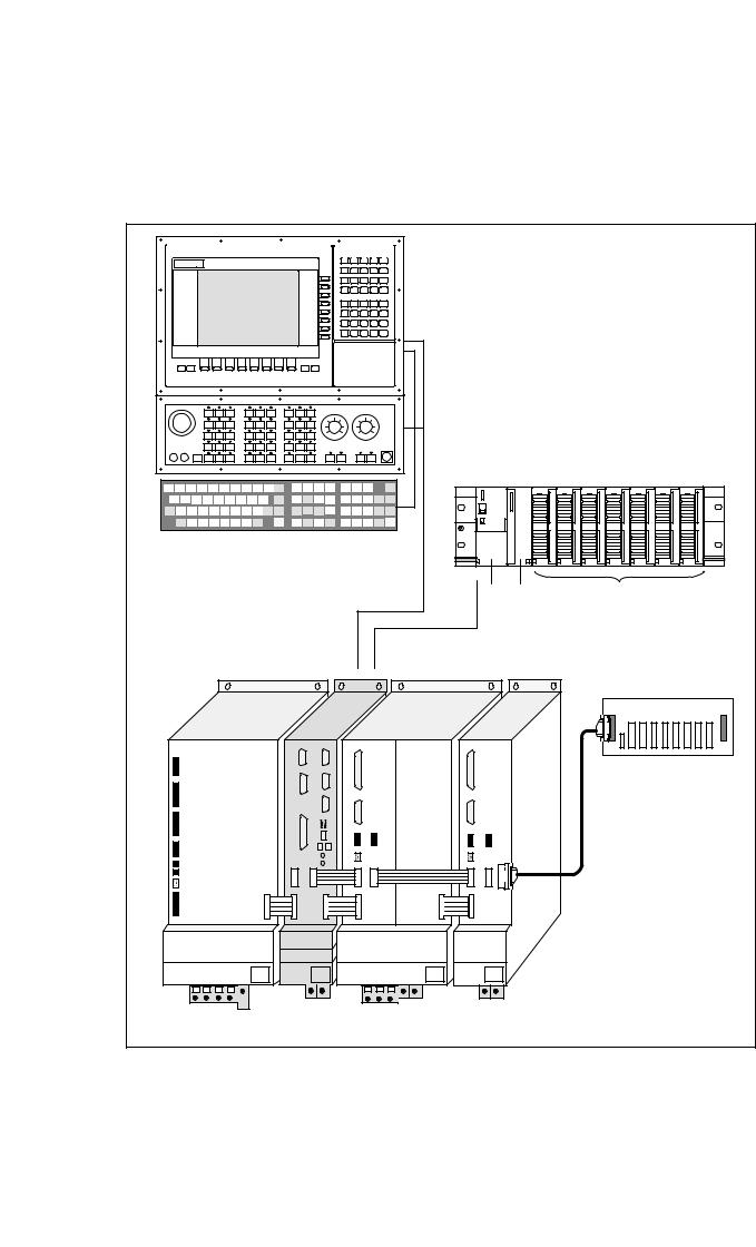
SIEMENS
Operator panel front
Machine control panel
QWERTY keyboard
PS AM |
SMs |
SIMATIC STEP 7-300 I/O devices
NCU terminal block
SIMODRIVE 611D
SINUMERIK 840D
SIEMENS |
|
|
|
SIMODRIVE |
|
|
|
MS (I/RF, OI) |
NCU |
MSD |
FDD |
Fig. 2-1 System overview of SINUMERIK 840 with SIMODRIVE 611 (diagrammatic)
2-20 |
Siemens AG, 2002. All rights reserved |
SINUMERIK 840D Installation and Start-Up Guide (IAD) – 11.02 Edition |
10.00 |
2 Configuration |
2.1 |
Mechanical configuration |
2.1.2Mains infeed module
Mains infeed module
The mains infeed module performs the following tasks: |
2 |
SSupplies power for the SINUMERIK 840D and axis modules
SGenerates the DC link voltage for the motors
SRegenerative feedback (I/RF) or braking resistor (OI) for generator-mode operation.
Open-loop control infeed module OI
Infeed/regenerative feedback module I/RF
Arrangement of mains infeed module
If the internal braking resistance is not sufficient, pulsed resistor modules can be installed.
The I/RF module feeds excess DC link energy generated during braking back into the supply system.
The I/RF or OI module is installed as the first module on the left.
References: PJ1/ Planning Guide for SIMODRIVE 611D
Siemens AG, 2002. All rights reserved |
2-21 |
SINUMERIK 840D Installation and Start-Up Guide (IAD) – 11.02 Edition |
2 Configuration |
10.00 |
2.1Mechanical configuration
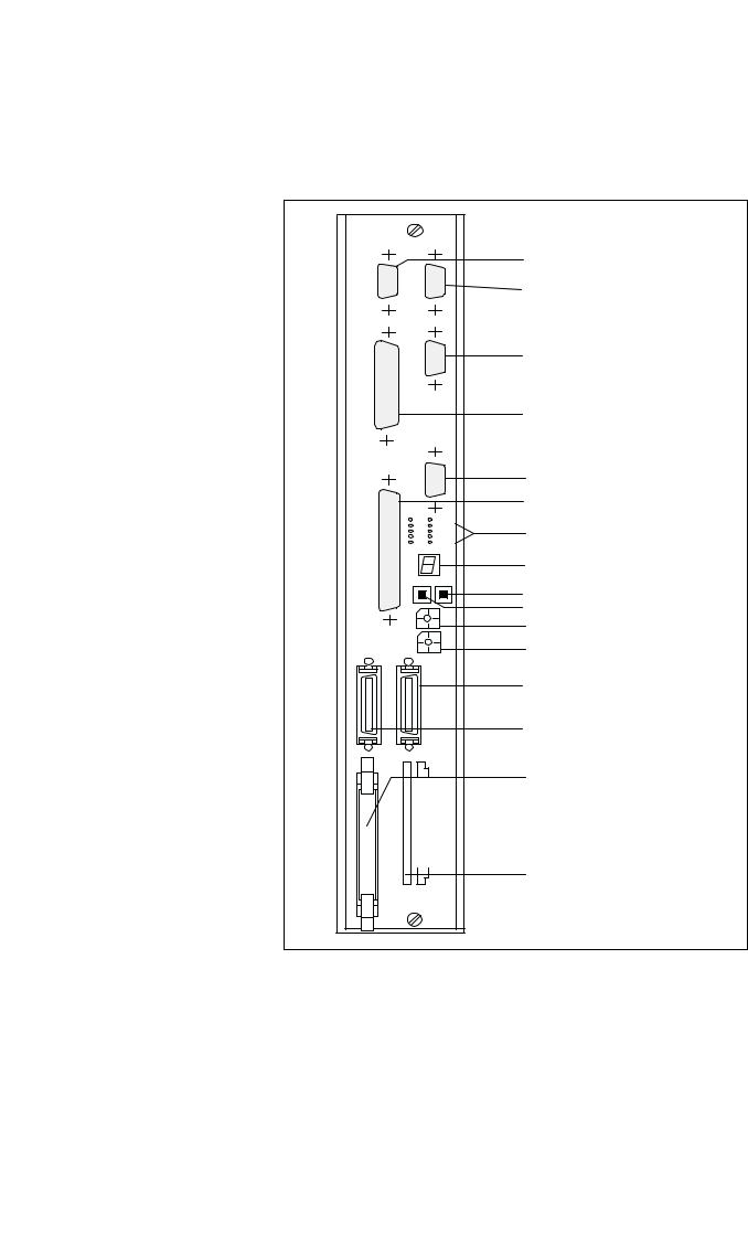
2.1.3NCU
2
|
X101 |
X102/ |
|
|
103 |
||
|
|
||
X111 |
|
|
|
|
|
X112 |
|
|
|
X122 |
|
|
|
+5 V |
PR |
|
|
NF |
PS |
X121 |
|
PF |
|
|
CF |
||
|
|
||
|
CB |
PF0 |
|
|
CP |
– |
|
|
|
|
|
|
|
RESET NMI |
|
|
|
|
S3 |
|
|
|
S4 |
|
X130B |
|
X130A |
|
X172 |
|
MEMORY CARD |
Operator panel front interface
L2DP
Reserved
P-BUS/K-BUS interface (PLC I/O devices)
PG-MPI interface I/O device interface
(cable distribution cabinet)
Various error and status LEDs (H1/H2)
7-segment display (H3)
NMI button (S2)
RESET button (S1)
NCK start-up switch
PLC start-up switch
SIMODRIVE 611D interface
Digitizing module connection
Device bus interface
PCMCIA slot (X173)
Fig. 2-2 Interfaces, control and display elements of NCU module
2-22 |
Siemens AG, 2002. All rights reserved |
SINUMERIK 840D Installation and Start-Up Guide (IAD) – 11.02 Edition |
10.00 |
2 Configuration |
2.2 Electrical configuration
2.1.4General configuration of SINUMERIK 840D
2
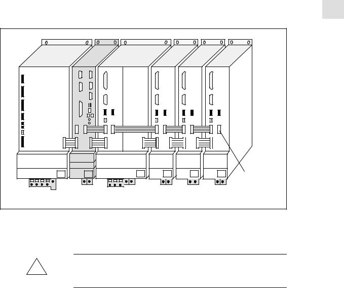
SIEMENS |
|
|
|
|
|
SIMODRIVE |
|
|
|
|
Bus terminating |
|
|
|
|
connector |
|
|
|
|
|
|
|
MS (I/RF, OI) |
NCU |
MSD |
FDD |
FDD |
FDD |
Fig. 2-3 General configuration of SINUMERIK 840D
Please note:
Caution
!When installing the drive group, please make sure to keep a space of 100mm for air circulation on top and at the bottom.
2.2Electrical configuration
2.2.1Component connections
Siemens AG, 2002. All rights reserved |
2-23 |
SINUMERIK 840D Installation and Start-Up Guide (IAD) – 11.02 Edition |

2 Configuration |
10.00 |
2.2Electrical configuration
24V power supply
2
COM1
PS/2 mouse
PS/2 keyboard
LPT1 VGA
Cover plate for PCI slot |
Cover plate for PCI/ISA |
connection |
slot connection |
|
PCU 50 |
USB |
(rear view) |
|
COM2 MPI/DP
Ethernet
MCP
X20
(rear view)
NCU
–X101 –X102
L2DP
MPI bus cable
|
|
|
–X111 |
|
|
|
|
|
|
–X112 |
|
SIMATIC S7-300 AM connecting cable |
|
|
–X122 |
||
|
|
|
|||
|
MPI cable |
|
|
|
|
HHU |
|
|
|
|
|
X1 |
X5 |
|
–X121 |
|
|
X2 |
|
|
|
|
|
|
X4 |
|
|
|
|
|
X3 |
|
|
|
|
|
HHU handwheel |
|
|
||
|
Distributor box |
Cable distribution |
X130B |
X130A |
|
SIMATIC S7-300 I/O devices |
cabinet |
||||
|
|
||||
|
|
|
|||
|
X2 |
|
–X172 |
MEMORY CARD |
|
|
|
|
|
||
Reserved for servicing
MPI cable
or
MPI-PG cable
PS AM |
SMs |
|
|
to drive bus |
|
IN |
OUT |
|
X20 |
X21 |
PG |
NCU terminal block
Fig. 2-4 Connection configuration
2-24 |
Siemens AG, 2002. All rights reserved |
SINUMERIK 840D Installation and Start-Up Guide (IAD) – 11.02 Edition |
10.00 |
|
|
2 Configuration |
|
|
|
|
2.2 |
Electrical configuration |
||
|
|
|
|
|
|
|
Note |
|
|
|
|
|
For cables and connectors, see |
|
|
|
|
|
References: |
/PHD/, Configuring Manual 840D |
|
|
2 |
|
|
|
|
|
|
|
|
|
|
|
|
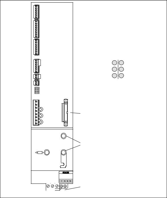
2.2.2 Connection of mains infeed module (OI, I/RF)
X111
X121
X141
X161
X171
X172
LED displays
LED displays
Electronics power |
Red |
|
Red |
5V voltage |
|
||||
|
level faulty |
|||
supply faulty |
|
|
||
|
|
|
Device ready |
|
Device is not ready, |
|
|
|
|
|
|
|
||
Green |
|
Yellow (DC link |
||
no enable signal (term. 63, |
|
|
precharged) |
|
64 or 48) |
Red |
|
|
|
Mains fault |
|
Red |
DC link over- |
|
|
|
voltage |
||
|
|
|||
|
|
|
|
|
X351
X181
Device bus
P600
DC link connection
M600
Power supply
U1 V1 W1 PE1
Fig. 2-5 Interfaces for OI and I/RF module 10–55kW
Siemens AG, 2002. All rights reserved |
2-25 |
SINUMERIK 840D Installation and Start-Up Guide (IAD) – 11.02 Edition |

2 Configuration |
10.00 |
2.2Electrical configuration
2
Relay contact for |
NC contact |
Ready message |
|
|
NO contact |
Relay contact for group message
I2t and motor overtemperature
Pulse enable Enable voltage Enable voltage Drive enable signal
Reference potential for enable voltage
P24
P15
N15
N24 M M
RESET (R+term.15)
Enable voltage
Setting-up mode Contactor energization,
start
Signaling contact from mains contactor
Enabling signal for internal mains contactor
Signaling contact for starting lockout (NC contact)
DC link power supply for mains buffering
External infeed for electronics power supply
External infeed for electronics power supply
External infeed for electronics power supply
74
73.2
73.1
72
5.3
5.2
5.1
63
9
9
64
19
7
45
44
10
15
15
R
9
112
48
111
213
113
NS1
NS2
AS1
AS2
M500
P500
2U1
1U1
2V1
1V1
2W1
1W1
–X111
–X121
–X141
–X161
–X171
–X172
LED displays
–X181
Fig. 2-6 Connection terminals on SIMODRIVE 611 mains supply module 10–55 kW
2-26 |
Siemens AG, 2002. All rights reserved |
SINUMERIK 840D Installation and Start-Up Guide (IAD) – 11.02 Edition |
10.00 |
|
2 Configuration |
|
2.2 |
Electrical configuration |
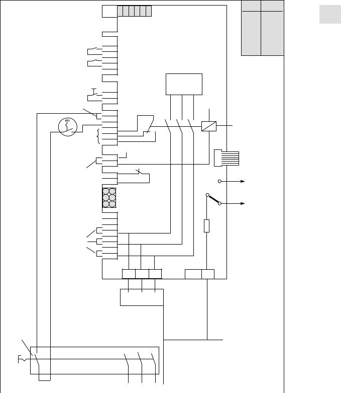
Typical circuit |
I/RF module |
|
|
|
S1.6 |
S1.5 |
S1.4 |
S1.3 |
S1.2 |
S1.1 |
S1–DIP switch |
|
S1 |
Default |
2 |
|
|
|
S1.1 |
OFF |
||||||||
|
|
|
|
|||||||||
|
|
|
X111 |
|
|
|
|
|
||||
|
|
|
|
|
|
|
|
S1.2 |
OFF |
|
||
|
|
|
|
|
|
|
|
Mains supply module |
S1.3 |
OFF |
|
|
|
|
|
|
|
|
|
|
S1.4 |
OFF |
|
||
|
|
|
|
|
|
|
|
|
|
|
||
|
|
X121 |
|
|
|
|
|
S1.5 |
OFF |
|
||
|
63 |
|
|
|
|
|
S1.6 |
OFF |
|
|||
|
|
|
|
|
|
|
|
|
|
|||
|
9 |
|
|
|
|
|
|
|
|
|
|
|
|
9 |
|
|
|
|
|
|
|
|
|
|
|
|
64 |
|
|
|
|
|
|
|
|
|
|
|
|
19 |
|
|
|
|
|
|
|
|
|
|
|
Pushbutton contact |
|
X141 |
|
|
|
Power |
|
|
|
|
||
|
|
|
|
section |
|
|
|
|
||||
|
|
|
|
|
|
|
|
|
||||
|
|
|
|
|
|
|
|
|
|
|
|
|
|
15 |
|
|
|
|
|
|
|
|
|
|
|
1) |
R |
|
|
|
|
|
|
|
L– |
|
|
|
|
|
|
|
|
|
|
|
|
|
|
|
|
|
9 |
X161 |
|
|
|
|
|
|
|
|
||
|
112 |
|
|
|
|
|
Internal mains |
|
||||
|
48 |
|
|
|
|
|
|
|
|
|
||
|
111 |
|
|
|
|
|
|
|
|
contactor |
|
|
|
213 |
|
|
|
|
|
|
|
|
|
|
|
|
113 |
|
|
|
|
|
|
|
|
|
|
|
|
|
|
|
L+ |
|
|
|
|
X351 |
|
|
|
|
NS1 |
X171 |
|
|
|
|
Device bus |
|
||||
1) |
NS2 |
|
|
|
|
|
|
|
|
|
|
|
|
|
|
|
|
|
|
|
|
|
|
|
|
|
AS1 |
X172 |
|
|
|
|
P600 |
P600 |
|
|
||
|
AS2 |
|
|
|
|
|
|
|
|
|
|
|
|
|
|
|
|
|
|
|
|
|
to the |
|
|
|
|
LEDs |
|
|
|
|
|
axis modules |
|
|||
|
|
|
|
|
|
|
|
|
|
M600 |
|
|
|
M500 |
|
|
|
|
|
|
|
M600 |
|
|
|
|
|
|
|
|
|
|
|
|
|
|
|
|
|
P500 |
X181 |
|
|
|
|
100 k |
|
|
|
||
|
2U1 |
|
|
|
|
|
|
|
|
|
|
|
|
1U1 |
|
|
|
|
|
|
|
|
|
|
|
1) |
2V1 |
|
|
|
|
|
|
|
|
|
|
|
1V1 |
|
|
|
|
|
|
|
|
|
|
|
|
|
|
|
|
|
|
|
|
|
|
|
|
|
|
2W1 |
|
|
|
|
|
|
|
|
|
|
|
|
1W1 |
|
|
|
|
|
|
|
|
|
|
|
|
|
|
U1 |
V1 |
W1 |
X131 |
PE |
|
|
|
||
|
Commutating |
1U2 |
1V2 |
1W2 |
|
|
|
|
|
|
|
|
|
|
|
|
reactor for |
|
|
|
|
|
|
|
I/RF module or |
|
|
|
|
|
|
|
|
|
|
|
|
|
|
|
OI module only |
1U1 |
1V1 |
1W1 |
|
|
|
|
Mains fuses for |
|
|
1) Jumpers inserted in |
|||
|
|
|
|
|
|
delivery state |
|
|
I/RF or OI |
|
|
|
|
|
|
|
|
|
|
|
|
|
|
Leading |
module |
|
|
|
|
|
|
contact |
Master switch |
|
|
|
|
|
|
|
|
|
|
|
|
|
|
|
|
|
|
|
|
|
|
|
|
|
|
|
|
|
Important! |
|
|
|
|
|
|
|
|
|
|
|
|
|
|
|
Terminal 48 must be de-ener- |
|
|
|
|
|
|
|
gized 10 msec before the mains |
|
|
|
|
|
|
|
contacts of the master switch |
|
|
|
|
|
|
|
open (e.g. by means of leading |
|
Supply L1 |
L2 |
L3 |
PE |
contact) |
||
|
|
||||||
|
|
|
|
|
|
|
|
Fig. 2-7 Example of three-conductor connection (standard circuit)
Siemens AG, 2002. All rights reserved |
2-27 |
SINUMERIK 840D Installation and Start-Up Guide (IAD) – 11.02 Edition |

2 Configuration |
10.00 |
2.2Electrical configuration
2.2.3Motor connection
2 |
2-axis FDD module |
1-axis FDD/MSD module |
||
|
||||
X411 |
X412 |
X411 |
|
|
Motor |
Motor encoder |
Motor |
|
|
encoder |
Axis 2 |
encoder |
|
|
Axis 1 |
|
|
||
|
|
|
||
X421 |
X422 |
X421 |
|
|
Direct position |
Direct position |
Direct position |
|
|
Axis 1 |
Axis 2 |
|
|
|
X431 |
X432 |
X431 |
X432 |
|
Relay terminals |
Relay terminals |
|||
BERO) |
BEROR- |
|||
Pulse enable |
Pulse enable |
|||
terminals |
Terminals |
|||
|
|
|||
|
X35 |
|
X35 |
|
|
X34 |
|
X34 |
|
X141 |
X341 |
X141 |
X341 |
|
|
|
|||
Drive bus |
|
Drive bus |
|
|
X151 |
|
X151 |
|
|
Device bus |
X351 |
Device bus |
X351 |
|
|
|
|||
|
P600 |
|
P600 |
|
DC link |
|
DC link |
|
|
busbar |
|
busbar |
|
|
|
M600 |
|
M600 |
|
|
Rating plate |
|
Rating plate |
|
|
|
|
||
|
Motor |
|
|
|
|
connecting |
|
|
|
|
terminals |
|
|
|
|
A1 and A2 |
Motor |
X131 |
|
|
|
|||
|
PE terminals PE1 PE2 |
connecting |
||
|
terminals |
U2 V2 W2 PE1 PE2 |
||
|
|
|||
Fig. 2-8 Design of FDD/MSD modules
2-28 |
Siemens AG, 2002. All rights reserved |
SINUMERIK 840D Installation and Start-Up Guide (IAD) – 11.02 Edition |
10.00 |
|
2 Configuration |
|
|
2.2 |
Electrical configuration |
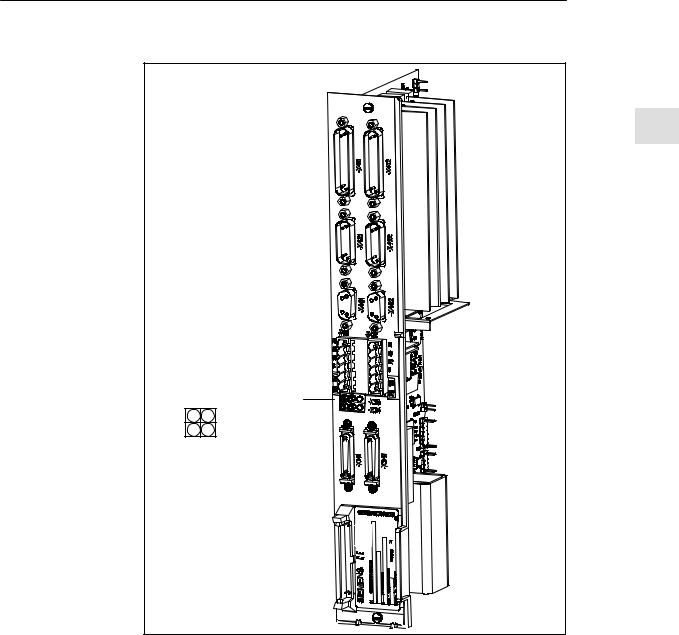
|
611D control |
|
|
|
module |
Performance 2 control |
|
|
Performance 2 |
|
|
|
(2-axis) |
|
2 |
|
|
X411 |
X412 |
|
|
Motor |
Motor encoder |
|
|
encoder |
Axis 2 |
|
|
Axis 1 |
|
|
|
X421 |
X422 |
|
|
Direct position |
|
|
|
Direct position |
|
|
|
Axis 2 |
|
|
|
Axis 1 |
|
|
|
|
|
X461 |
X462 |
|
BERO input, axis 1 |
BERO input, axis 2 |
|
X431 |
X432 |
|
Relay terminals |
||
BERO) |
||
Pulse enable |
||
terminals |
||
|
DAC assignment |
DACs |
||
DAC 1 |
DAC 2 |
||
|
|||
DAC 3 |
Ground |
|
|
X141 |
|
|
|
Drive bus
X151
Device bus
Fig. 2-9 611D control module Performance 2: Position and interface assignment
2.2.4Encoder connection
Motor measuring The motor measuring system of the connected motor must always be con- system and motor nected to connector X411 (see Fig. 2-8) of the same module. connection
Siemens AG, 2002. All rights reserved |
2-29 |
SINUMERIK 840D Installation and Start-Up Guide (IAD) – 11.02 Edition |
2 Configuration |
10.00 |
2.2Electrical configuration
|
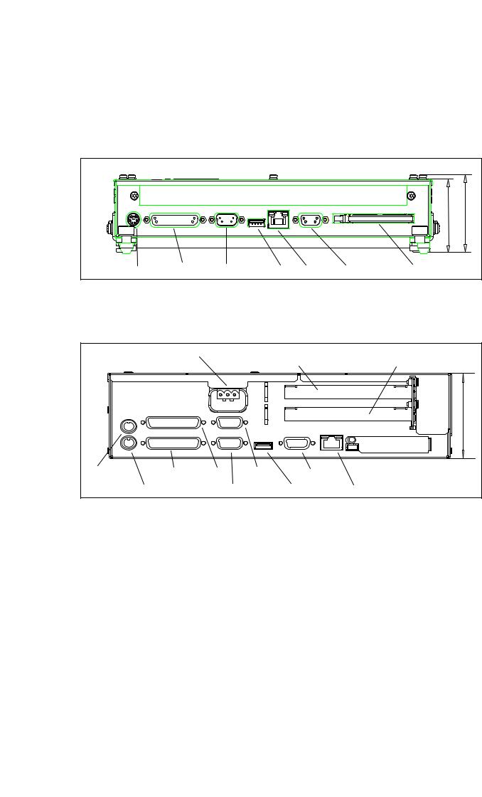
2.2.5 |
PCU 20 and PCU 50 connection |
|
2 |
PCU 20 |
|
|
|
|
53 |
Depth = 56 |
|
PS/2 mouse COM1/RS-232-C COM2/RS-232-C USB Ethernet MPI/L2-DP Flash Card/Memory Card |
||
|
Fig. 2-10 PCU 20 side view from right with interfaces |
|
|
PCU 50
24 V power supply |
Cover plate for PCI slot con- |
Cover plate for PCI/ISA |
|
nection |
slot connection |
Depth = 80
PS/2 mouse |
LPT1 |
COM1 |
COM2 |
MPI/DP |
|
|
|
|
(serial |
|
|
PS/2 keyboard |
VGA |
mouse) |
USB |
Ethernet |
|
Fig. 2-11 Side view of PCU 50 from right with interfaces
Interfaces The interfaces (e.g. pin assignments) are described and shown in detail in
References: /BH/, Operator Components Manual
2-30 |
Siemens AG, 2002. All rights reserved |
SINUMERIK 840D Installation and Start-Up Guide (IAD) – 11.02 Edition |
 Loading...