


Description of Functions 10/2004 Edition
sinumerik
SINUMERIK 840D/840Di/810D
Extended Functions

SINUMERIK 840D/840Di/ SINUMERIK 810D
Extended Functions
Description of Functions
Valid for |
|
|
Control |
Software Version |
|
SINUMERIK 840D powerline |
7 |
|
SINUMERIK 840DE powerline |
7 |
|
SINUMERIK 840Di |
|
3 |
SINUMERIK 840DiE (export version) |
3 |
|
SINUMERIK 810D powerline |
7 |
|
SINUMERIK 810DE powerline (exp.) |
7 |
|
10.2004 Edition
Digital and Analog NCK |
|
|
I/Os |
|
A4 |
Several OPs/NCUs |
|
B3 |
Operation via PC/PG |
|
B4 |
Remote Diagnostics |
|
F3 |
Manual and |
|
|
Handwheel Travel |
|
H1 |
Compensations |
|
K3 |
Mode Groups, Channels, |
|
|
Axis Replacement |
|
K5 |
Kinematic |
|
|
Transformations |
|
M1 |
Measurement |
|
M5 |
Software Cams, Position |
|
|
Switching Signals |
|
N3 |
Punching and Nibbling |
N4 |
|
Positioning Axes |
|
P2 |
Oscillation |
|
P5 |
Rotary Axes |
|
R2 |
Synchronous Spindle |
|
S3 |
Synchronized |
|
|
Actions |
s. FBSY |
|
Memory Configuration |
|
S7 |
Indexing Axes |
|
T1 |
Tool Change |
|
W3 |
Tool Compensation and |
|
|
Monitoring in Grinding |
W4 |
|
Index
3ls |
SINUMERIK Documentation |
|
Printing history
Brief details of this edition and previous editions are listed below.
The status of each edition is shown by the code in the “Remarks” columns.
Status code in the “Remarks” column:
A . . . . . New documentation.
B . . . . . Unrevised reprint with new Order No. C . . . . . Revised edition with new status.
If factual changes have been made on the page since the last edition, this is indicated by a new edition coding in the header on that page.
Edition |
Order No. |
Remarks |
06.94 |
6FC5297-0AC30-0BP0 |
A |
08.94 |
6FC5297-0AC30-0BP1 |
C |
02.95 |
6FC5297-2AC30-0BP0 |
C |
04.95 |
6FC5297-2AC30-0BP1 |
C |
03.96 |
6FC5297-3AC30-0BP0 |
C |
08.97 |
6FC5297-4AC30-0BP0 |
C |
12.97 |
6FC5297-4AC30-0BP1 |
C |
12.98 |
6FC5297-5AC30-0BP0 |
C |
08.99 |
6FC5297-5AC30-0BP1 |
C |
04.00 |
6FC5297-5AC30-0BP2 |
C |
10.00 |
6FC5297-6AC30-0BP0 |
C |
09.01 |
6FC5297-6AC30-0BP1 |
C |
11.02 |
6FC5297-6AC30-0BP2 |
C |
03.04 |
6FC5297-7AC30-0BP0 |
C |
10.04 |
6FC5297-7AC30-0BP1 |
C |
Trademarks
SIMATICr, SIMATIC HMIr, SIMATIC NETr, SIROTECr, SINUMERIKr and SIMODRIVEr are trademarks of Siemens. Other product names used in this documentation may be trademarks which, if used by third parties, could infringe the rights of their owners.
|
Other functions not described in this documentation might be |
|
executable in the control. However, no claim can be made regarding |
|
the availability of these functions when the equipment is first supplied |
Further information is available in the Internet at: |
or in the event of servicing. |
http://www.siemens.com/motioncontrol |
|
|
We have checked that the contents of this document correspond to |
This publication was produced with Interleaf V 7 |
the hardware and software described. Nevertheless, differences |
|
might exist and therefore we cannot guarantee that they are |
|
completely identical. The information given in this publication is |
|
reviewed at regular intervals and any corrections that might be |
|
necessary are made in the subsequent printings. Suggestions for |
|
improvement are also welcome. |
Siemens AG, 1994–2004. All rights reserved |
Subject to change without prior notice. |
|
|
Order No. 6FC5297-7AC30-0BP1 |
Siemens Aktiengesellschaft |
Printed in Germany |
|

10.04
Preface
Notes for the |
The SINUMERIK documentation is subdivided into 4 parts: |
|
reader |
S |
General Documentation |
|
||
|
S |
User Documentation |
|
S |
Manufacturer/Service documentation |
|
S |
OEM documentation |
This document is designed for machine tool manufacturers. It contains a detailed description of the scope of functions offered by SINUMERIK controls.
The function descriptions are only valid for the specific software version or up to the software version specified. You should request valid function descriptions for new software versions. Old function descriptions are only partly applicable for new software versions.
More detailed information about other SINUMERIK 840D/840Di/810D documents and publications for all SINUMERIK controllers (e.g. universal interface, measuring cycles, etc.) can be obtained from your local Siemens representative.
Note
It may be possible to run functions that are not described in this document in your controller. This does not, however, represent an obligation to supply such functions with a new control or when servicing.
Hotline |
If you have any questions about the control, please contact the following hotline: |
|
|
A&D Technical Support Tel.: |
+49 (180) 5050 222 |
|
Fax: |
+49 (180) 5050-223 |
|
Internet: http://www.siemens.com/automation/support-request |
|
|
If you have any queries about the documentation (suggestions, corrections), |
|
|
please fax them to the following number: |
|
|
Fax: |
+49 (9131) 98-2176 |
|
E-mail: motioncontrol.docu@erlf.siemens.de |
|
|
Fax form: See the reply form at the end of the brochure |
|
SINUMERIK |
http://www.siemens.com/motioncontrol |
|
Internet address |
|
|
Siemens AG, 2004. All rights reserved |
v |
SINUMERIK 840D/840Di/810D Descrip. of Functions Extended Functions (FB2) – 10.04 Edition |

09.01
10.04
SINUMERIK 840D |
Since 09.2001 the |
|
powerline |
S SINUMERIK 840D powerline and |
|
|
||
|
S |
SINUMERIK 840DE powerline |
|
have been available with improved performance. A list of available powerline |
|
|
modules can be found in Section 1.1 of the Hardware Reference Manual /PHD/. |
|
SINUMERIK 810D |
Since 12.2001 the |
|
powerline |
S SINUMERIK 810D powerline and |
|
|
||
|
S |
SINUMERIK 810DE powerline |
|
have been available with improved performance. A list of available powerline |
|
|
modules can be found in Section 1.1 of the Hardware Reference Manual /PHC/. |
|
Objective |
The function descriptions provide the information required for configuration and |
|
|
installation. |
|
Target groups |
The information contained in the function descriptions is designed for: |
|
|
S |
Design engineers |
S PLC programmers creating the PLC user program with the signals listed
S Start-up engineers once the system has been configured and set up
S Maintenance personnel inspecting and interpreting status signals and alarms
Notes on how to This Description of Functions is structured as follows: use this manual
SGeneral table of contents (overview) of the manual
SDescriptions of functions in alphanumeric order of the Description of Function codes
SAppendix with keyword index
Note
The Description of Functions Basic Machine (Part 1) contains both a general index as well as a reference list, a glossary of terms used and a list of abbreviations and acronyms.
Pages indicated provide the following information:
Part of the Description of Functions / Book / Chapter / Section / Subsection –
Page
vi |
Siemens AG, 2004. All rights reserved |
SINUMERIK 840D/840Di/810D Descrip. of Functions Extended Functions (FB2) – 10.04 Edition |

0910.01.04
If you need information about a particular function, you will find the function and the code under which it is sorted in the inside title page of the manual.
If you need information about a particular term, please look for the term in the section headed Index in the Appendix. The Description of Functions code, the chapter number and the number of the page on which you can find the information you need are listed in this section.
Chapters 4 and 5 of each Description of Functions contain definitions for “Active, data format, input limits”, etc. for the various signals and data.
An explanation of these definitions appears below under “Technical information”.
Important
! This documentation applies to:
D SINUMERIK 840D powerline control, software version 7
D SINUMERIK 810D powerline control, software version 7
D SINUMERIK 840Di control, software version 2
Equivalent software versions
The software versions specified in this documentation refer to the SINUMERIK 840D powerline and 810D powerline control systems with the parallel applicable software version. Whether individual functions have been approved for the control systems is not specified explicitly in each case, for further details, see /BU/, Catalog NC 60. The following applies:
Table 1-1 |
Equivalent software version |
|
|
||
|
|
|
|
|
|
SINUMERIK 840D |
|
|
SINUMERIK 810D |
SINUMERIK 840Di |
|
powerline |
|
|
powerline |
|
|
|
|
|
|
|
|
7.1 |
|
equivalent to |
|
7.1 |
3.1 |
|
|
|
|
|
|
Siemens AG, 2004. All rights reserved |
vii |
SINUMERIK 840D/840Di/810D Descrip. of Functions Extended Functions (FB2) – 10.04 Edition |

09.01
10.04
Explanation of symbols
Important
!This symbol is always displayed in this document to draw your attention to an important item of information.
Ordering Data Option
In this documentation you will find the symbol shown on the left with a reference to an ordering data option. The described function is only executable on the control if the control has the designated option.
Machine Manufacturer
This pictorial symbol appears in this document to indicate that the machine manufacturer can control or modify the function described. See machine manufacturer’s specifications.
Danger
!Indicates an imminently hazardous situation which, if not avoided, will result in death or serious injury or in substantial property damage.
Warning
!Indicates a potentially hazardous situation which, if not avoided, could result in death or serious injury or in substantial property damage.
Caution
!Used with the safety alert symbol indicates a potentially hazardous situation which, if not avoided, may result in minor or moderate injury or in property damage.
Caution
Used without safety alert symbol indicates a potentially hazardous situation which, if not avoided, may result in property damage.
viii |
Siemens AG, 2004. All rights reserved |
SINUMERIK 840D/840Di/810D Descrip. of Functions Extended Functions (FB2) – 10.04 Edition |

0910.01.04
Notice
Used without the safety alert symbol indicates a potential situation which, if not avoided, may result in an undesirable result or state.
Technical information
Notations |
The following notation and abbreviations are used in this documentation: |
|
S PLC interface signals –> IS “signal name” (signal data) |
|
E.g.: – IS “MMC-CPU1 ready” (DB10, DBX108.2) i.e. the signal is stored in |
|
data block 10, data byte 108, bit 2. |
|
– IS “Feedrate/Spindle speed override” (DB31-48, DBB0) i.e. the sig- |
|
nals for each axis/spindle are stored in data blocks 31 to 48, data block |
|
byte 0. |
|
S Machine data –> MD: MD_NAME (German name) |
|
S Setting data –> SD: SD_NAME (German name) |
|
S The symbol “8” means “corresponds to” |
Explanation of the abbreviations in Chapters 4 and 5
Values in the table
Default value
Value range (minimum and maximum)
Chapters 4 and 5 of each Description of Functions describe the data and signals which are significant for the respective function. Certain terms and abbreviations, which are used in these tabular descriptions, are explained here.
The machine data indicated in the Descriptions of Functions are always values for an NCU572.
The values for a different NCU (e.g. NCU570, NCU571, NCU573) are contained in the List Manual.
References: /LIS/, “Lists”
The machine data/setting data is preset to this value during start-up. In cases where different default values are used for different channels, this is indicated by a “ / ”.
Specifies the input limits. If no value range is specified, the data type determines the input limits and the field is marked “ ”.
Siemens AG, 2004. All rights reserved |
ix |
SINUMERIK 840D/840Di/810D Descrip. of Functions Extended Functions (FB2) – 10.04 Edition |

09.01
10.04
When changes take |
When machine data, setting data, etc. are altered, they are not immediately ac- |
||||
effect |
tive. The conditions for activation are therefore always specified. The possibili- |
||||
|
ties are shown in the following list in order of their priority: |
||||
|
S |
POWER ON (po) |
“RESET” key on front panel of the NCU module |
||
|
|
|
or switch power supply on/off |
||
|
S |
NEW_CONF (cf) |
– Reconfiguration of the PLC interface |
||
|
|
|
– “RESET” on control unit, or |
||
|
S |
RESET (re) |
“RESET” key on control unit or |
||
|
S |
Immediately (im) |
after entry of the value |
|
|
Protection level |
Protection levels 0 to 7 have been used. The lock for protection levels 0 to 3 (4 |
||||
|
to 7) can be canceled by entering the correct password (setting correct key- |
||||
|
switch position). The operator only has access to information protected by one |
||||
|
particular level and the levels below it. The machine data is assigned different |
||||
|
protection levels as a standard measure. |
|
|||
|
The table contains only the protection level for write operations. A fixed relation- |
||||
|
ship between read and write levels exists however: |
||||
|
|
|
|
|
|
|
|
Protection level for writing |
|
Protection level for reading |
|
|
|
|
|
|
|
|
|
0 |
|
|
0 |
|
|
|
|
|
|
|
|
1 |
|
|
1 |
|
|
|
|
|
|
|
|
2 |
|
|
4 |
|
|
|
|
|
|
|
References: |
/BA/, “Operator’s Guide” |
|
|
/FB/, A2, “Various Interface Signals” |
Unit |
The unit refers to the default setting of machine data SCALING_FACTOR_ |
|
|
USER_DEF_MASK and |
|
|
SCALING_FACTOR_USER_DEF. |
|
|
If the MD has no underlying unit, a “–” is shown in the box. |
|
x |
Siemens AG, 2004. All rights reserved |
SINUMERIK 840D/840Di/810D Descrip. of Functions Extended Functions (FB2) – 10.04 Edition |
0910.01.04
Data type |
The following data types are used in the control system: |
|
|
S |
DOUBLE |
|
|
Real or integer values (decimal values or whole numbers) |
|
|
Input limits from +/–4.19*10–307 to +/–1.67*10308 |
|
S |
DWORD |
|
|
Integer values |
|
|
Input limits from –2.147*109 to +2.147*109 |
|
S |
BOOLEAN |
|
|
Possible input values: true or false / 0 or 1 |
|
S |
BYTE |
|
|
Integer values from –128 to +127 |
|
S |
STRING |
|
|
Consisting of max. 16 ASCII characters (upper case letters, numbers and |
|
|
underscore) |
Data management The descriptions of the PLC interface in the individual Descriptions of Functions assume a theoretical maximum number of components:
S4 mode groups (associated signals stored in DB11)
S8 channels (associated signals stored in DB21-30)
S31 axes (associated signals stored in DB31-61)
For details of the actual number of components which can be implemented with each software version, please refer to
References: /BU/, “Order Document”, Catalog NC 60
J
Siemens AG, 2004. All rights reserved |
xi |
SINUMERIK 840D/840Di/810D Descrip. of Functions Extended Functions (FB2) – 10.04 Edition |

09.01
10.04
Notes
xii |
Siemens AG, 2004. All rights reserved |
SINUMERIK 840D/840Di/810D Descrip. of Functions Extended Functions (FB2) – 10.04 Edition |

10.04
SINUMERIK 840D/840Di/810D
Description of Functions
Extended Functions (FB2)
Digital and Analog NCK I/Os (A4)
1 |
Brief Description . . . . . . . . . . . . . . . . . . . . . . . . . . . . . . . . . . . . . . . . . . . . . . . . . . |
2/A4/1-3 |
|
2 |
Detailed Description . . . . . . . . . . . . . . . . . . . . . . . . . . . . . . . . . . . . . . . . . . . . . . . |
2/A4/2-5 |
|
|
2.1 |
General functionality . . . . . . . . . . . . . . . . . . . . . . . . . . . . . . . . . . . . . . . |
2/A4/2-5 |
|
2.2 |
Digital inputs/outputs of the NCK . . . . . . . . . . . . . . . . . . . . . . . . . . . . . |
2/A4/2-11 |
|
2.2.1 |
Digital inputs of the NCK . . . . . . . . . . . . . . . . . . . . . . . . . . . . . . . . . . . . |
2/A4/2-11 |
|
2.2.2 |
Digital outputs of the NCK . . . . . . . . . . . . . . . . . . . . . . . . . . . . . . . . . . |
2/A4/2-13 |
2.3Connecting and logic operations of fast NCK inputs/outputs . . . . . 2/A4/2-16
|
2.4 |
Analog inputs/outputs of the NCK . . . . . . . . . . . . . . . . . . . . . . . . . . . . |
2/A4/2-18 |
|
2.4.1 |
Analog inputs of the NCK . . . . . . . . . . . . . . . . . . . . . . . . . . . . . . . . . . . |
2/A4/2-18 |
|
2.4.2 |
Analog outputs of the NCK . . . . . . . . . . . . . . . . . . . . . . . . . . . . . . . . . . |
2/A4/2-21 |
|
2.5 |
PLC I/Os directly addressable from NC (SW 5 and higher) . . . . . . |
2/A4/2-24 |
|
2.6 |
Analog value representation of the analog input and |
|
|
|
output values of the NCK . . . . . . . . . . . . . . . . . . . . . . . . . . . . . . . . . . . |
2/A4/2-31 |
|
2.7 |
Comparator inputs . . . . . . . . . . . . . . . . . . . . . . . . . . . . . . . . . . . . . . . . . |
2/A4/2-33 |
3 |
Supplementary Conditions . . . . . . . . . . . . . . . . . . . . . . . . . . . . . . . . . . . . . . . . . |
2/A4/3-37 |
|
4 |
Data Descriptions (MD, SD) . . . . . . . . . . . . . . . . . . . . . . . . . . . . . . . . . . . . . . . . . |
2/A4/4-39 |
|
|
4.1 |
General machine data . . . . . . . . . . . . . . . . . . . . . . . . . . . . . . . . . . . . . . |
2/A4/4-39 |
|
4.2 |
General setting data . . . . . . . . . . . . . . . . . . . . . . . . . . . . . . . . . . . . . . . |
2/A4/4-54 |
5 |
Signal Descriptions . . . . . . . . . . . . . . . . . . . . . . . . . . . . . . . . . . . . . . . . . . . . . . . . |
2/A4/5-55 |
|
|
5.1 |
NC specific signals . . . . . . . . . . . . . . . . . . . . . . . . . . . . . . . . . . . . . . . . . |
2/A4/5-55 |
|
5.1.1 |
Overview of signals from PLC to NC (DB10) . . . . . . . . . . . . . . . . . . . |
2/A4/5-55 |
|
5.1.2 |
Description of signals from PLC to NC (DB10) . . . . . . . . . . . . . . . . . |
2/A4/5-58 |
|
5.1.3 |
Overview of signals from NC to PLC (DB10) . . . . . . . . . . . . . . . . . . . |
2/A4/5-63 |
|
5.1.4 |
Description of signals from NC to PLC (DB10) . . . . . . . . . . . . . . . . . |
2/A4/5-64 |
6 |
Example |
. . . . . . . . . . . . . . . . . . . . . . . . . . . . . . . . . . . . . . . . . . . . . . . . . . . . . . . . . . |
2/A4/7-67 |
7 |
Data Fields, Lists . . . . . . . . . . . . . . . . . . . . . . . . . . . . . . . . . . . . . . . . . . . . . . . . . . |
2/A4/7-67 |
|
|
7.1 |
Interface signals . . . . . . . . . . . . . . . . . . . . . . . . . . . . . . . . . . . . . . . . . . . |
2/A4/7-67 |
|
7.2 |
Machine Data . . . . . . . . . . . . . . . . . . . . . . . . . . . . . . . . . . . . . . . . . . . . . |
2/A4/7-68 |
Siemens AG, 2004. All rights reserved |
2/A4/i |
SINUMERIK 840D/840Di/810D Descrip. of Functions Extended Functions (FB2) – 10.04 Edition |

10.04
7.3 |
Setting data . . . . . . . . . . . . . . . . . . . . . . . . . . . . . . . . . . . . . . . . . . . . . . . |
2/A4/7-69 |
7.4 |
Interrupts . . . . . . . . . . . . . . . . . . . . . . . . . . . . . . . . . . . . . . . . . . . . . . . . . |
2/A4/7-69 |
|
|
J |
2/A4/ii |
Siemens AG, 2004. All rights reserved |
SINUMERIK 840D/840Di/810D Descrip. of Functions Extended Functions (FB2) – 10.04 Edition |
10.04 |
Digital and Analog NCK I/Os (A4) |
1 Brief Description
Brief Description |
1 |
General |
Signals can be read and output in the interpolation cycle via the ”digital and |
|
|
analog NCK I/Os”. The following functions can be executed with these signals, |
|
|
for example: |
|
|
S Several feed values in one block |
|
|
S Several auxiliary functions in a block |
|
|
S Rapid retraction on finished contour |
|
|
S Axis-specific delete distance-to-go |
|
|
S |
Program branches |
|
S |
Rapid NC start |
|
S |
Analog calipers |
|
S |
Position switching signals |
|
S |
Punching/nibbling functions |
|
S |
Analog value control |
|
S |
etc. |
Contents |
This Description of Functions describes the specifications for the digital and |
|
|
analog I/Os. |
|
|
The note “References” lists documentation relating to any function which utilizes |
|
|
these I/Os. |
|
J
Siemens AG, 2004. All rights reserved |
2/A4/1-3 |
SINUMERIK 840D/840Di/810D Descrip. of Functions Extended Functions (FB2) – 10.04 Edition |

Digital and Analog NCK I/Os (A4) |
10.04 |
1 Brief Description
Notes
2/A4/1-4 |
Siemens AG, 2004. All rights reserved |
SINUMERIK 840D/840Di/810D Descrip. of Functions Extended Functions (FB2) – 10.04 Edition |
10.04 |
Digital and |
Analog NCK I/Os (A4) |
|
2.1 |
General functionality |
Detailed Description |
2 |
2.1General functionality
General |
The ability to control or influence time-critical NC functions is dependent on |
||
|
high-speed NCK I/O interfaces or the facility to rapidly address particular PLC |
||
|
I/Os (see Section 2.5). |
|
|
|
On the SINUMERIK 840D, 840Di system, therefore, |
||
|
a) digital and analog NCK inputs and outputs can be used (see Chapter 3). |
||
|
b) specific PLC I/Os can be addressed directly (see Section 2.5). |
||
|
The hardware inputs and outputs can be read and written via system variables |
||
|
in the parts program or synchronized actions. |
||
|
Via the PLC interface, both the signal states of the digital I/Os and the values of |
||
|
the external analog I/Os can be changed by the PLC user program according to |
||
|
the application. |
|
|
840D hardware |
On the SINUMERIK 840D onboard NCU there are 4 digital NCK inputs (inputs |
||
|
1 to 4) and 4 digital NCK outputs (outputs 1 to 4). |
||
|
The digital onboard inputs and outputs are stored in the first address byte. With |
||
|
the NCK outputs, the remaining signals of this byte (NCK outputs 5 to 8) can be |
||
|
used via the PLC interface (digital NCK outputs without hardware). |
||
|
Using the “NCU terminal block” that can be coupled to the drive bus, it is |
||
|
possible to connect further digital NCK inputs/outputs and analog NCK |
||
|
inputs/outputs (hereafter called external NCK I/Os). The “NCU terminal block” |
||
|
is used as a carrier module for up to eight DP compact plug-in modules. Up to |
||
|
two “NCU terminal blocks” can be connected per NCU. |
||
|
The maximum degree of expansion of the external NCK I/Os is: |
||
|
S 32 digital NCK inputs |
(digital inputs 9 to 40) |
|
|
S 32 digital NCK outputs |
(digital outputs 9 to 40) |
|
|
S 8 analog NCK inputs |
(analog inputs 1 to 8) |
|
|
S 8 analog NCK outputs |
(analog outputs 1 to 8) |
|
|
For further information about the hardware specification see: |
||
|
References: |
/PHD/, SINUMERIK 840D, NCU Manual |
|
Siemens AG, 2004. All rights reserved |
2/A4/2-5 |
SINUMERIK 840D/840Di/810D Descrip. of Functions Extended Functions (FB2) – 10.04 Edition |

Digital and Analog NCK I/Os (A4) |
10.04 |
2.1 General functionality |
|
840 Di hardware digital I/Os
Digital inputs/outputs are provided for the SINUMERIK 840Di via the MCI Board Extension module. The following connections are available:
S2 handwheels
S2 probes
S4 digital inputs/outputs
Note
The MCI Board Extension module is an option for the SINUMERIK 840Di. The PIN assignment of the cable distribution interface (X121) matches the cable distributor assignment on the SINUMERIK 840D.
SINUMERIK 840Di |
Analog and digital inputs/outputs can be operated on the SINUMERIK 840Di by |
analog and digital |
means of SIMATIC S7 bus interface and signal boards linked via the |
inputs/outputs |
PROFIBUS-DP. |
PLC I/Os for direct |
Up to 16 bytes for digital input signals and analog input values plus a total of 16 |
addressing by |
bytes for digital output signals and analog output values can be addressed |
NCK SW 5.2 |
directly by the parts program. These bytes must be taken into account when the |
|
PLC is configured. They must be programmed consecutively. They are |
|
processed directly by the PLC operating system. As a result, the signal transfer |
|
time between the NC and PLC I/O modules is of a magnitude of 0.5 ms. |
Caution
!The output bytes specified for the NCK may not be write-accessed by the PLC user program as the access operations between the NCK and PLC would be uncoordinated.
For further details, see 2.5.
Comparator |
In addition to the digital and analog NCK inputs, 16 internal comparator inputs |
inputs |
(comparator input bytes 1 and 2) are also available. |
|
The signal state of a comparator input is formed by comparing an analog input |
|
signal with a threshold value in a setting data. |
|
For more information please refer to Section 2.7. |
Number |
The number of addressable digital NCK input/output bytes and analog |
|
inputs/outputs must be programmed by means of general machine data. |
2/A4/2-6 |
Siemens AG, 2004. All rights reserved |
SINUMERIK 840D/840Di/810D Descrip. of Functions Extended Functions (FB2) – 10.04 Edition |

10.04 |
Digital and Analog NCK I/Os (A4) |
Hardware assignment of external NCK I/Os
2.1 General functionality
Machine data ($MN_ ... ) |
Number of active ... |
Max. |
|
|
number |
|
|
|
FASTIO_DIG_NUM_INPUTS |
Digital NCK input bytes |
5 |
|
|
|
FASTIO_DIG_NUM_OUTPUTS |
Digital NCK output bytes |
5 |
|
|
|
FASTIO_ANA_NUM_INPUTS |
Analog NCK inputs |
8 |
|
|
|
FASTIO_ANA_NUM_OUTPUTS |
Analog NCK outputs |
8 |
|
|
|
Note
The 1st byte is always assigned to the 4 digital I/Os on the MCI Board Extension module on the SINUMERIK 840Di. Even if you have not connected an MCI Board Extension module to the SINUMERIK 840Di, the 1st byte is always assigned to it.
For this reason, at least 2 bytes must always be entered in machine data FASTIO_DIG_NUM... if you want to operate further I/Os via the PROFIBUS.
Corresponding alarms are generated if the parts program addresses inputs/outputs that have not been defined in the above machine data.
These NCK inputs or outputs do not have to actually exist in the hardware. If they do not, the signal states or the binary analog values are set to “zero” in a defined way inside the NCK. The values can be changed by the PLC.
The following general machine data ($MN–) are provided for assigning I/O signal modules or I/O modules to external NCK I/Os:
S MD 10366: HW_ASSIGN_DIG_FASTIN[hw] Hardware assignment for external digital inputs
SMD 10368: HW_ASSIGN_DIG_FASTOUT[hw] Hardware assignment for
external digital outputs
S MD 10362: HW_ASSIGN_ANA_FASTIN[hw] Hardware assignment for external analog inputs
SMD 10364: HW_ASSIGN_ANA_FASTOUT[hw] Hardware assignment for
external analog outputs
[hw]: Index for addressing the external digital I/O bytes (0 to 3) or the external analog inputs/outputs (0 to 7)
Note
The hardware assignment is different on the SINUMERIK 840D and 840Di controls.
The defaults for the assignment of I/Os for the SINUMERIK 840Di via machine data MD 10362 to MD 10368 are as follows:
Siemens AG, 2004. All rights reserved |
2/A4/2-7 |
SINUMERIK 840D/840Di/810D Descrip. of Functions Extended Functions (FB2) – 10.04 Edition |
Digital and Analog NCK I/Os (A4) |
10.04 |
2.1 General functionality |
|
Modification to MD for PROFIBUS DP
Machine data ($MN_ ... ) |
Meaning |
Default |
|
|
|
HW_ASSIGN_ANA_FASTIN[0] |
Assignment for analog input |
050000A0 |
... |
(16-bit access) |
|
|
|
|
HW_ASSIGN_ANA_FASTOUT[0] |
Assignment for analog output |
050000A0 |
... |
(16-bit access) |
|
|
|
|
HW_ASSIGN_DIG_FASTIN[0] |
Assignment for digital input |
05000090 |
... |
(8-bit access) |
|
|
|
|
HW_ASSIGN_DIG_FASTOUT[0] |
Assignment for digital output |
05000090 |
... |
(8-bit access) |
|
|
|
|
The machine data $MN_HW_ASSIGN_... have been modified for hardware operation on the PROFIBUS DP of the SINUMERIK 840Di.
The assignment of bytes 1 to 4 has been redefined. The machine data assignments below apply for PROFIBUS DP operation:
Byte |
New for PROFIBUS-DP |
Old meaning |
4th byte |
Segment number = 5 |
Segment number |
3rd byte |
Not used = 0 |
Module number |
2nd byte |
Logical address high |
Submodule number |
1st byte |
Logical address low |
Input/output number |
Guidelines for machine data $MN_HW_ASSIGN_...:
SLogical address in 1st and 2nd byte is specified in hexadecimal format. Example: 050001A2 (Hex) equals logical address 418 (Dec).
SAddress 0 is reserved for the PLC and cannot be used as an NC I/O.
SThe value 05000000 in MD $MN_HW_ASSIGN_... is interpreted as “Slot does not physically exist”. The input is then treated like a simulation input.
System variables The following table lists the system variables with which NCK I/Os can be read or written directly by the parts program.
The number of the NCK input/output is used for addressing.
The following applies to n:
1 n 8 * MD 10350: FASTIO_DIG_NUM_INPUTS
1 n 8 * MD 10360: FASTIO_DIG_NUM_OUTPUTS
1 n MD 10300: FASTIO_ANA_NUM_INPUTS
1 n MD 10310: FASTIO_ANA_NUM_OUTPUTS
System variable |
Meaning |
Range of [n] |
|
|
|
$A_IN[n] |
Read digital NCK input [n] |
1 to 3, 9 to 40 |
|
|
|
$A_INA[n] |
Read analog NCK input [n] |
1 to 8 |
|
|
|
$A_INCO[n] |
Read comparator input [n] |
1 to 16 |
|
|
|
PBB |
|
|
|
|
|
$A_OUT[n] |
Read/write digital NCK output [n] |
1 to 40 |
|
|
|
$A_OUTA[n] |
Read/write analog NCK output [n] |
1 to 8 |
|
|
|
2/A4/2-8 |
Siemens AG, 2004. All rights reserved |
SINUMERIK 840D/840Di/810D Descrip. of Functions Extended Functions (FB2) – 10.04 Edition |
10.04 |
Digital and |
Analog NCK I/Os (A4) |
|
2.1 |
General functionality |
Note
When this system variable is read by the parts program, a preprocess stop (STOPRE command) is initiated inside the control.
Weighting factor The weighting factors in the general machine data MD 10320: FASTIO_ANA_INPUT_WEIGHT[hw] and MD 10330: FASTIO_ANA_OUTPUT_WEIGHT[hw] allow each individual analog NCK input and output to be adapted to the AD or DA converters of the analog I/O module used.
If the correct weighting factor is set, the value set in system variable $A_OUTA[n] outputs the corresponding voltage value in millivolts at the analog output [n].
Example for 840D |
The analog value range is 10V (maximum modulation); |
|||||
|
FASTIO_ANA_OUTPUT_WEIGHT[hw] = 10000 (default on 840D) |
|||||
|
$A_OUTA[1] = 9500 |
; 9.5V is output at analog NCK output 1 |
||||
|
$A_OUTA[3] = –4120 ; –4.12V is output at analog NCK output 3 |
|||||
|
Application for analog NCK inputs/outputs without hardware: |
|||||
|
With weighting factor of 32767, the digitized analog values for parts program |
|||||
|
and PLC accesses are identical. In this way, it is possible to use the associated |
|||||
|
input or output word for a 1:1 communication between the parts program and |
|||||
|
the PLC. |
|
|
|
|
|
Assignment to |
Several NC functions are dependent on the functionality of the NCK I/Os. The |
|||||
NC functions |
NCK inputs and/or outputs used for these functions are assigned on a |
|||||
|
function-specific basis via machine data (e.g. MD 21220: |
|||||
|
MULTFEED_ASSIGN_FASTIN for “Multiple feedrates in one block”). A byte |
|||||
|
address must be specified in the machine data for the digital inputs/outputs; the |
|||||
|
assignment is always made byte by byte. |
|
|
|||
|
|
|
|
|||
|
Byte address |
|
Assignment for the digital NCK inputs/outputs |
|||
|
|
|
|
|
|
|
|
0 |
none |
|
|
|
|
|
|
|
|
|
|
|
|
840D: 1 |
1 to 4 (onboard I/Os) |
and |
5 to 8 |
(NCK-A without hardware) |
|
|
|
|
|
|
|
|
|
FM-NC: 1 |
|
1 |
to |
8 |
(NCK-A without hardware) |
|
|
|
|
|
|
|
|
2 |
|
9 |
to |
16 |
(external NCK I/Os) |
|
|
|
|
|
|
|
|
3 |
|
17 |
to |
24 |
(external NCK I/Os) |
|
|
|
|
|
|
|
|
4 |
|
25 |
to |
32 |
(external NCK I/Os) |
|
|
|
|
|
|
|
|
5 |
|
33 |
to |
40 |
(external NCK I/Os) |
|
|
|
||||
|
128 |
Inputs 1 to 8 of comparator byte 1 (see Section 2.7) |
||||
|
|
|
||||
|
129 |
Inputs 9 to 16 of comparator byte 2 (see Section 2.7) |
||||
|
|
|
|
|
|
|
Siemens AG, 2004. All rights reserved |
2/A4/2-9 |
SINUMERIK 840D/840Di/810D Descrip. of Functions Extended Functions (FB2) – 10.04 Edition |
Digital and Analog NCK I/Os (A4) |
10.04 |
2.1 General functionality |
|
Clocksynchronous processing
The I/O modules of the external NCK I/Os on the SINUMERIK 840D can be operated in one of the following two modes:
SAsynchronously, i.e. the input and output values are made available in cycles set by the terminal block which are asynchronous to the internal NC processing cycles.
SSynchronously, i.e. the input values and the output values are provided synchronously with the settable internal NC processing clock frequency.
The processing mode is selected for individual modules by means of general machine data MD 10384: HW_CLOCKED_MODULE_MASK[tb].
[tb] = Index for terminal block (0 to 1)
In synchronous processing mode, one of the following clock rates can be selected (general MD 10380: HW_UPDATE_RATE_FASTIO[tb]):
SSynchronous inputs/outputs in position control cycles (default setting)
SSynchronous inputs/outputs in interpolation cycles
It is possible to define a lead time in microseconds for the clocked NCK I/Os in general MD 10382: HW_LEAD_TIME_FASTIO[tb]. This makes it possible to consider the conversion time of the ADC for example, so that the digitized input value is available on the cycle.
The defined cycle frequency or delay time applies to all cycle-synchronous I/O modules of the terminal block addressed with [tb].
On the SINUMERIK FM-NC, the I/O modules of the external NCK I/Os always operate asychronously. They are updated in position control cycles.
Monitoring |
The following functional monitors are provided for external I/Os on the |
|
functions |
SINUMERIK 840D: |
|
|
S |
During booting: |
|
|
– Check whether the I/O modules in the terminal blocks match the MD |
|
|
assignments. |
|
S |
During cyclic operation: |
|
|
– Sign-of-life monitoring in interpolation cycles |
|
|
– Module monitoring in interpolation cycles |
|
|
– Temperature monitoring |
In the event of a fault, NC ready is canceled and an alarm is output.
Response to faults The digital and analog NCK outputs are switched to “safe” status (i.e. 0V at output) in the event of faults (e.g. NC ready = 0) in the NCU or power failures.
2/A4/2-10 |
Siemens AG, 2004. All rights reserved |
SINUMERIK 840D/840Di/810D Descrip. of Functions Extended Functions (FB2) – 10.04 Edition |
10.04 |
Digital and Analog NCK I/Os (A4) |
2.2 |
Digital inputs/outputs of the NCK |
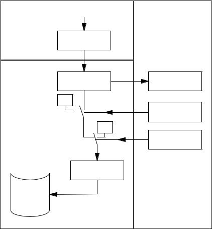
2.2Digital inputs/outputs of the NCK
2.2.1Digital inputs of the NCK
Number |
General MD 10350: FASTIO_DIG_NUM_INPUTS (number of active digital NCK |
|
input bytes) the available digital NCK inputs can be defined (in groups of 8). |
Function |
The digital NCK inputs allow external signals to be injected which can then be |
|
used, for example, to control the workpiece machining program sequence. With |
|
the system variable $A_IN[n], the signal status of the digital input [n] can be |
|
scanned directly in the parts program. |
|
The signal state at the hardware input can be changed by the PLC user |
|
program (see Fig. 2-1). |
Disable input |
The PLC user program can disable NCK inputs individually by means of |
|
interface signal “Disable digital NCK inputs” (DB10, DBB0 or DB122 ...). In this |
|
case, they are set to “0” in a defined manner inside the control. |
Set input from PLC |
The PLC can also apply interface signal “Setting digital NCK inputs on PLC” |
|
(DB10, DBB1 or DBB123 ...) to set each digital input to a defined “1” signal state |
|
(see Fig. 2-1). As soon as this interface signal is set to “1”, the signal state at |
|
the hardware input or the input disable is inactive. |
Read actual value |
The signal status of the digital NCK inputs is signaled to the PLC (interface |
|
signal “Actual value of digital NCK inputs” (DB10, DBB60, DBB186 ...)). The |
|
actual value reflects the real state of the signal at the hardware input; the |
|
influence of the PLC is therefore ignored in the “actual value” (see Fig. 2-1). |
RESET/power ON |
After power ON and reset, the signal level at the input is passed on. If |
behavior |
necessary, the PLC user program can disable or set the inputs to “1” in a |
|
defined manner as described above. |
Applications |
The program sequence can be controlled with conditional jump statements in |
|
the part program as a function of the signal status of an external hardware |
|
signal. |
Siemens AG, 2004. All rights reserved |
2/A4/2-11 |
SINUMERIK 840D/840Di/810D Descrip. of Functions Extended Functions (FB2) – 10.04 Edition |
Digital and Analog NCK I/Os (A4) |
10.04 |
2.2 Digital inputs/outputs of the NCK
For example, digital NCK inputs can be used for the following NC functions:
SDelete distance-to-go with positioning axes
SFast program branching at the end of block
SProgrammed read-in disable
SSeveral feedrates in one block
References: /FB/, S5, “Synchronized Actions”
The NCK inputs are assigned to the NC functions separately for each function and byte in the machine data. Multiple assignments of inputs are not monitored.
|
[n] |
|
|
NCK |
Hardware |
PLC |
|
input |
|||
|
|
||
|
Hardware input |
Actual value |
|
|
image |
(DB10, DBB60 ... ) |
|
|
“0” |
|
|
|
|
Disable |
|
|
|
(DB10, DBB0 ... ) |
|
|
“1” |
|
|
|
|
Setting by PLC |
|
|
|
(DB10, DBB1 ... ) |
|
Part program |
NCK value |
|
|
: |
|
|
|
$A_IN [n] |
|
|
|
: |
Digital input read in |
|
|
|
the parts program |
|
Fig. 2-1 Signal flow for digital NCK inputs
2/A4/2-12 |
Siemens AG, 2004. All rights reserved |
SINUMERIK 840D/840Di/810D Descrip. of Functions Extended Functions (FB2) – 10.04 Edition |
10.04 |
Digital and Analog NCK I/Os (A4) |
2.2 |
Digital inputs/outputs of the NCK |
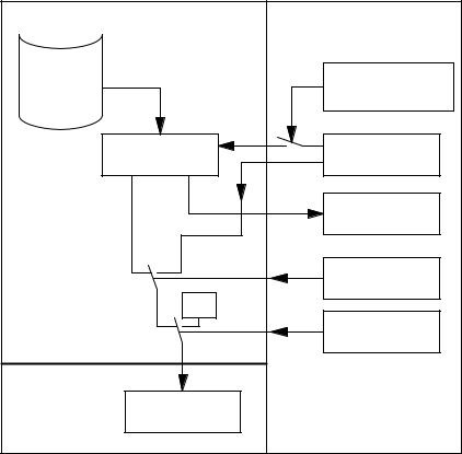
2.2.2Digital outputs of the NCK
Number |
General MD 10310: FASTIO_DIG_NUM_OUTPUTS (number of active digital |
|
NCK output bytes) the available digital NCK outputs can be defined (in groups |
|
of 8). |
Function |
The digital NCK outputs provide the option of outputting important switching |
|
commands at high speed as a function of the program processing status. With |
|
the system variable $A_OUT[n], the signal status of the digital output [n] can be |
|
set or read again directly in the parts program. |
|
There are also several ways of changing this set signal state via the PLC (see |
|
Fig. 2-2). |
Disable output |
The PLC user program is capable of disabling the digital NCK outputs |
|
individually with interface signal “Disable digital NCK outputs” (DB10, DBB4, |
|
DBB130...). In this case, the “0” signal is output at the hardware output (see |
|
Fig. 2-2). |
Overwrite screenform
Setting screen form
Every output that can be set by the NC parts program can be overwritten from the PLC using the overwrite screenform. Previous NCK values are then lost (see Fig. 2-2).
The following routine has to be carried out to overwrite the NCK value from the PLC:
1.The output in question must be preset with the required signal state at the PLC interface “PLC setting for digital NCK outputs” (DB10, DBB6, DBB132...).
2.The setting value becomes the new NCK value for the relevant output (DB10, DBB5, DBB131 ...) when the overwrite screenform is activated (signal transition 0 –> 1). This value remains operative until a new NCK value is programmed (by the PLC or from the NC part program).
Furthermore, a PLC setting for each output can determine whether the instantaneous (e.g. as specified by NC parts program) or the PLC value specified via the setting screen form (DB10, DBB7, DBB133 ...) should be sent to the hardware output (see Fig. 2-2).
The following routine has to be carried out to define the PLC value:
1.The output in question must be preset with the required signal state at the PLC interface “PLC setting for digital NCK outputs” (DB10, DBB6).
2.The setting screen form must be set to “1” for the output in question.
Unlike the overwrite screenform, the current NCK value is not lost when a value is set in the setting screen form. As soon as the PLC sets “0” in the setting screen form, the NCK value is again active.
Siemens AG, 2004. All rights reserved |
2/A4/2-13 |
SINUMERIK 840D/840Di/810D Descrip. of Functions Extended Functions (FB2) – 10.04 Edition |

Digital and Analog NCK I/Os (A4) |
10.04 |
2.2 Digital inputs/outputs of the NCK |
|
Read setpoint
RESET/
end of program
Power ON
Digital NCK outputs without hardware
Applications
Note
The same setting value (DB10, DBB6) is used at the PLC interface for the overwrite and setting screenforms. Therefore, an identical output signal state is the result if the signal state is changed simultaneously in the overwrite and setting screenform.
The instantaneous NCK value at the digital outputs can be read by the PLC user program (interface signal “setpoint of digital NCK outputs” (DB10, DBB64, DBB186 ...)). Please note that this setpoint ignores disabling and the setting screen form of the PLC. The setpoint can therefore be different from the actual signal state at the hardware output (see Fig. 2-2).
On end of program or RESET, every digital output can be defined as necessary by the PLC user program in the overwrite screenform, setting screen form or disable signal.
After power ON, the digital outputs are set to “0” in a defined manner. This can be overwritten in the PLC user program according to the application using the screen forms described above.
No alarm is output if the digital NCK outputs written from the part program have been defined in general MD 10360: FASTIO_ANA_NUM_INPUTS, but do not exist as hardware outputs. The NCK value can be read by the PLC (IS “Setpoint ...”)
This function allows digital hardware outputs to be set instantaneously by bypassing the PLC cycles. Time-critical switching functions can thus be triggered in connection with the machining process and under program control (e.g. on block change).
For example digital NCK outputs are required for the following NC functions:
SPosition signals
References: /FB/, N3, “Software Cams, Position Signals”
S Output of the comparator signals (see Section 2.7)
The NCK outputs are assigned to the NC functions separately for each function in machine data. Multiple assignments of outputs are checked during power ON and indicated by an alarm.
2/A4/2-14 |
Siemens AG, 2004. All rights reserved |
SINUMERIK 840D/840Di/810D Descrip. of Functions Extended Functions (FB2) – 10.04 Edition |
10.04 |
Digital and Analog NCK I/Os (A4) |
2.2 Digital inputs/outputs of the NCK
Part program |
NCK |
PLC |
|
Digital output set in |
|
: |
the parts program |
|
|
Overwrite screenform |
|
$A_OUT [n] |
|
|
|
(DB10, DBB5 ... ) |
|
: |
|
|
|
(Signal transition 0!1) |
|
|
|
|
|
NCK value |
Setting val. from PLC |
|
(DB10, DBB6 ... ) |
|
|
|
|
|
|
Setpoint |
|
|
(DB10, DBB64 ... ) |
|
(PLC value) |
Setting screen form |
|
|
|
|
|
(DB10, DBB7 ... ) |
|
“0” |
|
|
|
Disable |
|
|
(DB10, DBB4 ... ) |
|
Hardware |
|
|
output [n] |
|
Fig. 2-2 Signal flow for digital NCK outputs
Siemens AG, 2004. All rights reserved |
2/A4/2-15 |
SINUMERIK 840D/840Di/810D Descrip. of Functions Extended Functions (FB2) – 10.04 Edition |
Digital and Analog NCK I/Os (A4) |
10.04 |
2.3 Connecting and logic operations of fast NCK inputs/outputs |
|
2.3Connecting and logic operations of fast NCK inputs/outputs
Function |
In SW 4 and higher, the fast inputs of the NCK I/Os can be set in the software |
|
according to the signal states of the fast outputs. |
|
Overview: |
Output: |
Input: |
– Byte |
– Byte |
– Bit |
– Bit |
Alternatives:
1. Connect
2. OR operation
3. AND operation
Connect |
The fast input of the NCK I/O is set to the signal state of the assigned fast |
|
output. |
OR operation |
The fast input of the NCK I/O takes the signal state which is given by the OR |
|
operation of the output signal with the assigned input signal. |
AND operation |
The fast input of the NCK I/O takes the signal state which is given by ANDing |
|
the output signal with the assigned input signal. |
Special cases
SIf several output bits are assigned to the same input bit, then the one with the highest MD index becomes effective.
SIf inputs or outputs are specified which do not exist or are not activated, then the assignment is ignored without alarm. Checking of the active bytes of the NCK I/Os is performed via the entries in the machine data:
MD 10350: FASTIO_DIG_NUM_INPUTS and MD 10360: FASTIO_DIG_NUM_OUTPUTS.
2/A4/2-16 |
Siemens AG, 2004. All rights reserved |
SINUMERIK 840D/840Di/810D Descrip. of Functions Extended Functions (FB2) – 10.04 Edition |
10.04 |
|
|
|
|
|
Digital and Analog NCK I/Os (A4) |
|||
|
|
|
2.3 Connecting and logic operations of fast NCK inputs/outputs |
||||||
Defining |
The assignments are specified via machine data: |
|
|
||||||
assignments |
|
|
MD 10361 : FASTIO_DIG_SHORT_CIRCUIT[n]. |
||||||
|
n can assume values between 0 and 9, in other words, up to 10 assignments |
||||||||
|
can be defined. |
|
|
|
|
|
|
||
|
2 hexadecimal characters in each case are provided for the specification of the |
||||||||
|
byte and bit of an output. The type of logic operation is specified by entering |
||||||||
|
|
|
0 |
for connect |
|
|
|
|
|
|
|
|
A |
for AND operation |
|
|
|
|
|
|
|
|
B...for OR operation |
|
|
|
|
||
|
in bits 12 – 15 of the input. |
|
|
|
|
||||
|
|
|
|
|
|
|
|
|
|
|
|
|
FASTIO_DIG_SHORT_CIRCUIT[n] |
|
|
|
|
||
|
|
|
|
|
|
|
|
|
|
|
|
|
Output |
Input |
|
|
|||
|
|
|
|
|
|
|
|
|
|
|
|
|
Bit |
|
Byte |
|
Bit |
Byte |
|
|
|
|
|
|
|
↑ Type of logic op. |
|
|
|
|
Bit |
24–31 |
|
16–23 |
8–15 |
0–7 |
|||
Examples |
|
|
|
|
|
|
|
|
|
Connect: |
|
|
|
|
|
|
|||
|
MD 10361: FASTIO_DIG_SHORT_CIRCUIT = ’04010302H’ |
|
|
||||||
output 4, byte 1, connect to input 3, byte 2
AND operation:
MD 10361: FASTIO_DIG_SHORT_CIRCUIT = ’0705A201H’ output 7, byte 5 AND with
input 2, byte 1
OR operation:
MD 10361: FASTIO_DIG_SHORT_CIRCUIT = ’0103B502H’ output 1, byte 3, OR with
input 5, byte 2
Siemens AG, 2004. All rights reserved |
2/A4/2-17 |
SINUMERIK 840D/840Di/810D Descrip. of Functions Extended Functions (FB2) – 10.04 Edition |
Digital and Analog NCK I/Os (A4) |
10.04 |
2.4 Analog inputs/outputs of the NCK |
|
2.4Analog inputs/outputs of the NCK
2.4.1Analog inputs of the NCK
Number |
General MD 10300: FASTIO_ANA_NUM_INPUTS (number of active analog |
|
NCK inputs) the available analog NCK inputs can be defined. |
Function |
The system variable $A_INA[n] allows the value at the analog NCK input [n] to |
|
be directly accessed in the parts program. |
|
The analog value at the hardware input can also be influenced by the PLC user |
|
program (see Fig. 2-3). |
Disable input |
The PLC user program is capable of disabling the analog NCK inputs |
|
individually with interface signal “Disable analog NCK inputs” (DB10, DBB146). |
|
In this case, they are set to “0” in a defined manner inside the control. |
Set input from PLC |
The PLC can also specify a value for each analog NCK input by applying the |
|
interface signal “Setting screen form of analog NCK inputs” (DB10, DBB147) |
|
(see Fig. 2-3). As soon as this interface signal is set to “1”, the value set by the |
|
PLC (DB10, DBB148 to 163) becomes active for the analog input. The analog |
|
value at the hardware input or the input disable is then inactive. |
Read actual value |
The interface signal “Actual value of analog input of NCK” (DB10, DBB194 to |
|
209) transfers the analog values that are actually present at the hardware inputs |
|
to the PLC. The possible influence of the PLC is therefore ignored in the actual |
|
value (see Fig. 2-3). |
RESET/power ON |
After power ON and RESET, the analog value at the input is passed on. If |
behavior |
necessary, the PLC user program can manipulate the NCK inputs as described |
|
above in the PLC user program. |
Weighting factor |
Using the weighting factor in the general MD 10320: |
|
FASTIO_ANA_INPUT_WEIGHT[hw] it is possible to adapt each analog NCK |
|
input to the various ADCs for reading in the parts program (see Fig. 2-3). |
|
In this machine data it is necessary to enter the value x that is to be read in the |
|
parts program with the system variable $A_INA[n], if the corresponding analog |
|
input [n] is set to the maximum value or if the value 32767 is set for this input via |
|
the PLC interface. The voltage level at the analog input is then read with the |
|
system variable $A_INA[n] as a numerical value with the unit millivolts. |
2/A4/2-18 |
Siemens AG, 2004. All rights reserved |
SINUMERIK 840D/840Di/810D Descrip. of Functions Extended Functions (FB2) – 10.04 Edition |
 Loading...