


D-Link® DGS-1016D
DGS-1024D
16/24-Port 10/100/1000Mbps
Gigabit Ethernet Switch
Manual
Building Networks for People
RECYCLABLE
(March 2012)

D-Link DGS-1016D/DGS-1024D Unmanaged Gigabit Ethernet Switch
Information in this document is subject to change without notice. © 2012 D-Link Corporation. All rights reserved.
Reproduction in any manner whatsoever without the written permission of D-Link Corporation is strictly forbidden.
Trademarks used in this text: D-Link and the D-LINK logo are trademarks of D-Link Corporation; Microsoft and Windows are registered trademarks of Microsoft Corporation.
Other trademarks and trade names may be used in this document to refer to either the entities claiming the marks and names or their products. D-Link Corporation disclaims any proprietary interest in trademarks and trade names other than its own.
FCC Warning
This equipment has been tested and found to comply with the limits for a Class A digital device, pursuant to Part 15 of the FCC Rules. These limits are designed to provide reasonable protection against harmful interference when the equipment is operated in a commercial environment. This equipment generates, uses, and can radiate radio frequency energy and, if not installed and used in accordance with this user’s guide, may cause harmful interference to radio communications. Operation of this equipment in a residential area is likely to cause harmful interference in which case the user will be required to correct the interference at his own expense.
CE Mark Warning
This is a Class A product. In a domestic environment, this product may cause radio interference in which case the user may be required to take adequate measures.
Warnung!
Dies ist ein Produkt der Klasse A. Im Wohnbereich kann dieses Produkt Funkstoerungen verursachen. In diesem Fall kann vom Benutzer verlangt werden, angemessene Massnahmen zu ergreifen.
Precaución!
Este es un producto de Clase A. En un entorno doméstico, puede causar interferencias de radio, en cuyo case, puede requerirse al usuario para que adopte las medidas adecuadas.
Attention!
Ceci est un produit de classe A. Dans un environnement domestique, ce produit pourrait causer des interférences radio, auquel cas l`utilisateur devrait prendre les mesures adéquates.
Attenzione!
Il presente prodotto appartiene alla classe A. Se utilizzato in ambiente domestico il prodotto può causare interferenze radio, nel cui caso è possibile che l`utente debba assumere provvedimenti adeguati.
VCCI Warning
被要求採取某些適當的對策。
ii

CONTENTS
PREFACE………………………………………………….……………IV
NOTES, NOTICES, AND CAUTIONS ............................................................ |
IV |
SAFETY INSTRUCTIONS.............................................................................. |
V |
General Precautions for Rack-Mountable Products......................... |
vii |
Protecting Against Electrostatic Discharge ...................................... |
ix |
INTRODUCTION…………………………………………………….…1 |
|
SWITCH DESCRIPTION ............................................................................... |
1 |
Switch Features .................................................................................. |
2 |
Gigabit Ethernet Technology.............................................................. |
3 |
802.1p and QoS .................................................................................. |
3 |
D-LINK GREEN TECHNOLOGY .................................................................. |
5 |
FRONT-PANEL COMPONENTS.................................................................... |
6 |
LED Indicators ................................................................................... |
6 |
Cable Diagnostics............................................................................. |
16 |
POWER INPUT ON REAR PANEL............................................................... |
10 |
INSTALLATION………………………………………………….…….12 |
|
Package Contents ............................................................................. |
12 |
BEFORE YOU CONNECT TO THE NETWORK............................................ |
13 |
Mounting the Switch on a Rack ........................................................ |
14 |
Attaching the Rubber Feet ................................................................ |
15 |
Provide for Adequate Ventilation ..................................................... |
15 |
POWER ON ............................................................................................... |
16 |
Power Failure................................................................................... |
16 |
CONNECTING THE SWITCH………………………………………..17 |
|
Connect to an End Node ................................................................... |
18 |
Connect to Hub or Switch................................................................. |
19 |
Connect to Network Backbone or Server.......................................... |
20 |
TECHNICAL SPECIFICATIONS…………………………………….21 GLOSSARY………………………………………………………………24
iii

D-Link DGS-1016D/DGS-1024D Unmanaged Gigabit Ethernet Switch
Preface
The DGS-1016D/DGS-1024D Manual is divided into sections that describe the system installation and operating instructions with examples.
Section 1, Introduction - A description of the physical features of the Switch, including LED indicators, ports and panel descriptions.
Section 2, Installation – A description of the physical installation of the Switch, mounting the Switch in a equipment rack and powering on the Switch.
Section 3, Connecting the Switch – A description of how to connect your Switch to an end node, hub, another switch or backbone server.
Appendix Technical Specifications - The technical specifications of the DGS-1016D/DGS-1024D.
Notes, Notices, and Cautions
NOTE: A NOTE indicates important information that helps you make better use of your device.
NOTICE: A NOTICE indicates either potential damage to hardware or loss of data and tells you how to avoid the problem.
CAUTION: A CAUTION indicates the potential for property damage, personal injury or death.
iv

D-Link DGS-1016D/DGS-1024D Unmanaged Gigabit Ethernet Switch
Safety Instructions
Use the following safety guidelines to ensure your own personal safety and to help protect your system from potential damage. Throughout this safety section, the caution icon (  ) is used to indicate cautions and precautions that you need to review and follow.
Safety Cautions
To reduce the risk of bodily injury, electrical shock, fire, and damage to the equipment, observe the following precautions.
Observe and follow service markings. Do not service any product except as explained in your system documentation. Opening or removing covers that are marked with the triangular symbol with a lightning bolt may expose you to an electrical shock. Only a trained service technician should service components inside these compartments.
If any of the following conditions occur, unplug the product from the electrical outlet and replace the part or contact your trained service provider:
–The power cable, extension cable, or plug is damaged.
–An object has fallen into the product.
–The product has been exposed to water.
–The product has been dropped or damaged.
–The product does not operate correctly when you follow the operating instructions.
•Keep your system away from radiators and heat sources. Also, do not block cooling vents.
•Do not place any device on top of Switch, or place the Switch on top of any device or object that will block the free flow of air through the ventilation slots on the sides, top, and bottom of the Switch’s case.
•Keep your hand away from top and bottom of device that generates a significant amount of heat.
•Do not spill food or liquids on your system components, and never operate the product in a wet environment. If the system gets wet, see the appropriate section in your troubleshooting guide or contact your trained service provider.
•Do not push any objects into the openings of your system. Doing so can cause a fire or an electric shock by shorting out interior components.
•Use the product only with approved equipment.
•Allow the product to cool before removing covers or touching internal components.
•Operate the product only from the type of external power source indicated on the electrical ratings label. If you are not sure of the type of power source
required, consult your service provider or local power company.
v

D-Link DGS-1016D/DGS-1024D Unmanaged Gigabit Ethernet Switch
Safety Instructions (continued)
•To help avoid damaging your system, be sure the voltage selection Switch (if provided) on the power supply is set to match the power available at your location:
–115 volts (V)/60 hertz (Hz) in most of North and South America and some Far Eastern countries such as South Korea and Taiwan
–100 V/50 Hz in eastern Japan and 100 V/60 Hz in western Japan.
–230 V/50 Hz in most of Europe, the Middle East, and the Far East.
•Also be sure that attached devices are electrically rated to operate with the power available in your location.
•Use only approved power cable(s). If you have not been provided with a power cable for your system or for any AC-powered option intended for your system, purchase a power cable that is approved for use in your country. The power cable must be rated for the product and for the voltage and current marked on the product's electrical ratings label. The voltage and current rating of the cable should be greater than the ratings marked on the product.
•To help prevent an electric shock, plug the system and peripheral power cables into properly grounded electrical outlets. These cables are equipped with threeprong plugs to help ensure proper grounding. Do not use adapter plugs or remove the grounding prong from a cable. If you must use an extension cable, use a 3-wire cable with properly grounded plugs.
•Observe extension cable and power strip ratings. Make sure that the total ampere rating of all products plugged into the extension cable or power strip does not exceed 80 percent of the ampere ratings limit for the extension cable or power strip.
•To help protect your system from sudden, transient increases and decreases in electrical power, use a surge suppressor, line conditioner, or uninterruptible power supply (UPS).
•Position system cables and power cables carefully; route cables so that they cannot be stepped on or tripped over. Be sure that nothing rests on any cables.
•Do not modify power cables or plugs. Consult a licensed electrician or your power company for site modifications. Always follow your local/national wiring rules.
•When connecting or disconnecting power to hot-pluggable power supplies, if offered with your system, observe the following guidelines:
–Install the power supply before connecting the power cable to the power supply.
–Unplug the power cable before removing the power supply.
–If the system has multiple sources of power, disconnect power from the system by unplugging all power cables from the power supplies.
•Move products with care; ensure that all casters and/or stabilizers are firmly connected to the system. Avoid sudden stops and uneven surfaces.
vi

D-Link DGS-1016D/DGS-1024D Unmanaged Gigabit Ethernet Switch
Safety Instructions (continued)
General Precautions for Rack-
Mountable Products
•Observe the following precautions for rack stability and safety. Also refer to the rack installation documentation accompanying the system and the rack for specific caution statements and procedures.
•Systems are considered to be components in a rack. Thus, "component" refers to any system as well as to various peripherals or supporting hardware.
CAUTION: Installing systems in a rack without the front and side stabilizers installed could cause the rack to tip over, potentially resulting in bodily injury under certain circumstances. Therefore, always install the stabilizers before installing components in the rack.
After installing system/components in a rack, never pull more than one component out of the rack on its slide assemblies at one time. The weight of more than one extended component could cause the rack to tip over and may result in serious injury.
• Before working on the rack, make sure that the stabilizers are secured to the rack, extended to the floor, and that the full weight of the rack rests on the floor. Install front and side stabilizers on a single rack or front stabilizers for joined multiple racks before working on the rack.
vii
D-Link DGS-1016D/DGS-1024D Unmanaged Gigabit Ethernet Switch
Safety Instructions (continued)
•Always load the rack from the bottom up, and load the heaviest item in the rack first.
•Make sure that the rack is level and stable before extending a component from the rack.
•Use caution when pressing the component rail release latches and sliding a component into or out of a rack; the slide rails can pinch your fingers.
•After a component is inserted into the rack, carefully extend the rail into a locking position, and then slide the component into the rack.
•Do not overload the AC supply branch circuit that provides power to the rack. The total rack load should not exceed 80 percent of the branch circuit rating.
•Ensure that proper airflow is provided to components in the rack.
•Do not step on or stand on any component when servicing other components in a rack.
CAUTION: Never defeat the ground conductor or operate the equipment in the absence of a suitably installed ground conductor. Contact the appropriate electrical inspection authority or an electrician if you are uncertain that suitable grounding is available.
CAUTION: The system chassis must be positively grounded to the rack cabinet frame. Do not attempt to connect power to the system until grounding cables are connected. Completed power and safety ground wiring must be inspected by a qualified electrical inspector. An energy hazard will exist if the safety ground cable is omitted or disconnected.
viii

D-Link DGS-1016D/DGS-1024D Unmanaged Gigabit Ethernet Switch
Protecting Against Electrostatic Discharge
Static electricity can harm delicate components inside your system. To prevent static damage, discharge static electricity from your body before you touch any of the electronic components, such as the microprocessor. You can do so by periodically touching an unpainted metal surface on the chassis.
You can also take the following steps to prevent damage from electrostatic discharge (ESD):
1.When unpacking a static-sensitive component from its shipping carton, do not remove the component from the antistatic packing material until you are ready to install the component in your system. Just before unwrapping the antistatic packaging, be sure to discharge static electricity from your body.
2.When transporting a sensitive component, first place it in an antistatic container or packaging.
3.Handle all sensitive components in a static-safe area. If possible, use antistatic floor pads, workbench pads, and an antistatic grounding strap.
ix

SECTION 1
Introduction
Switch Description
Switch Features
D-Link Green Technology
Ports
Front-Panel Components
LED Indicators
Power Input on Rear Panel
Switch Description
The 16-port DGS-1016D and 24-port DGS-1024D Switches provide dedicated 10, 100 or 1000 Mbps Ethernet bandwidth on each port. The ports will automatically detect the speed, duplex and MDI/MDIX status of the device it is connecting to, and adjust these settings accordingly. The Switch ports can be used to network computers, printers, servers, routers, other switches or any device equipped with an Ethernet port. For best performance, use Category 5 or better Ethernet cabling.
This stand alone Switch is very easy to set up. There is no network management is required; simply power on the Switch and connect the cables.
However, please keep in mind that the standard rules of available Ethernet cable length from one device to another which cannot exceed 100 meters (or 300 feet).
1
Switch Features
The DGS-1016D 16-Port and DGS-1024D 24-port Switches do not require any management. Both Switches are designed for easy installation, flexibility and high performance. Connect devices to the Switch as the scale and volume of network traffic increases.
Support 10/100/1000 Base-T on both 16 and 24 ports models
Store and Forward Switching Method
Cable Diagnostics while boot-up
D-Link Green Technology
Auto Negotiation on Duplex Mode
Auto MDI/MDIX supported
Support Full/Half Duplex Transfer Mode on 10/100 Mbps
Support Full Duplex Transfer Mode on 1000 Mbps
Wire-Speed reception and transmission
8K absolute MAC Address
512 KBytes RAM for data buffering
Easy to read diagnostic LEDs
IEEE 802.3x Flow Control for Full-duplex mode
Back Pressure Flow Control for Half-duplex mode
IEEE 802.1p QoS (support 4 Queues, Strict Mode)
Jumbo Frame support (9600Bytes)
Support IEEE802.3az EEE & D-Link innovative EEE+ for more power saving
2
Gigabit Ethernet Technology
Gigabit Ethernet is an extension of IEEE 802.3 Ethernet utilizing the same packet structure, format, and support for CSMA/CD protocol, full duplex, flow control, and management objects, but with a tenfold increase in theoretical throughput over 100-Mbps Fast Ethernet and a hundredfold increase over 10-Mbps Ethernet. Since it is compatible with all 10-Mbps and 100-Mbps Ethernet environments, Gigabit Ethernet provides a straightforward upgrade without wasting a company’s existing investment in hardware, software and trained personnel.
The increased speed and extra bandwidth offered by Gigabit Ethernet is necessary to coping with the network bottlenecks; more computers and their bus speeds getting faster, and more applications generate more traffic in the network. Upgrading key components, such as your backbone and servers to Gigabit Ethernet can greatly improve network response times as well as significantly speed up the traffic between your subnets.
Gigabit Ethernet supports video conferencing, complex imaging and similar data-intensive applications. Likewise, since data transfers occur 10 times faster than Fast Ethernet, servers outfitted with Gigabit Ethernet NIC’s are able to perform 10 times the number of operations in the same amount of time.
802.1p and QoS
The DGS-1024D and DGS-1016D Switches support 802.1p priority queuing Quality of Service. The implementation of QoS (Quality of Service) and benefits of using 802.1p priority queuing are described here.
Advantages of QoS
QoS is an implementation of the IEEE 802.1p standard that allows network administrators a method of reserving bandwidth for important functions that require a large bandwidth or have a high priority, such as VoIP (voice-over Internet Protocol), web browsing applications, file server applications or video conferencing. Not only
3
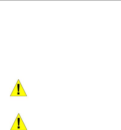
can a larger bandwidth be created, but other less critical traffic can be limited, so bandwidth can be saved. The Switch has separate hardware queues on every physical port to which packets from various applications are mapped to and assigned a priority. The illustration below shows how 802.1P priority queuing is implemented on the Switch. The eight IEEE 802.1P priority levels defined by the standard are mapped to the four class queues used in the Switch.
Mapping QoS on the Switch
The picture above shows the default priority setting for the Switch. Class-3 has the highest priority of the four priority queues on the Switch. In order to implement QoS, the user is required to instruct the Switch to examine the header of a packet to see if it has the proper identifying tag tagged. Then the user may forward these tagged packets to designated queues on the Switch where they will be emptied, based on priority.
"The DUT support strict mode for 802.1p QoS. The untagged pkt will follow the priority 0 to work (i.e. class 1)."
Understanding QoS
The Switch has four priority queues. These priority queues are labeled as 3, the high queue to 0, the lowest queue. The eight priority tags, specified in IEEE 802.1p are mapped to the Switch's priority tags as follows:
•Priority 0 is assigned to the Switch's Q1 queue.
4
•Priority 1 is assigned to the Switch's Q0 queue.
•Priority 2 is assigned to the Switch's Q0 queue.
•Priority 3 is assigned to the Switch's Q1 queue.
•Priority 4 is assigned to the Switch's Q2 queue.
•Priority 5 is assigned to the Switch's Q2 queue.
•Priority 6 is assigned to the Switch's Q3 queue.
•Priority 7 is assigned to the Switch's Q3 queue.
The Switch uses strict priority for Scheduling. Strict priority-based scheduling, any packets residing in the higher priority queues are transmitted first.
D-Link Green Technology
•IEEE 802.3az Energy-Efficient Ethernet (EEE):
It is the first standard in the history of Ethernet to address proactive reduction in energy consumption for networked devices. The IEEE 802.3 EEE standard defines mechanisms and protocols intended to reduce the energy consumption of network links during periods of low utilization, by transitioning interfaces into a low-power state without interrupting the network connection.
•EEE+:
•D-Link provides an EEE+ function allowing the user to reduce energy when the device is at low utilization and the link partner is a non-EEE compliance switch.
•By default, the EEE+ function is disabled. Users can manually turn on the EEE+ function by the switch on the front panel to enable power savings.
•Power Saving Technology:
•Power saving by link status.
If there is no link on a port, such as when there is no computer connected to the port or the connected computer is
5
powered off, D-Link’s Green Technology will enter a "sleep mode", drastically reducing power used for that port.
•Power saving by cable length: 0~20m, 21~100m.
D-Link’s Green Technology detects the length of connected Ethernet cable and adjusts power usage accordingly without affecting performance. This way, a port connected to a 20m cable only uses as much power as it needs, instead of using full power, which is only needed for 100m cables.
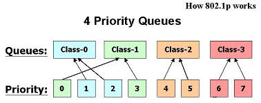
Front-Panel Components
On the front panel of the Switch you will see the following.
•LED status indicators
•16 Auto-Negotiating 10/100/1000Mbps ports on the DGS1016D
•24 Auto-Negotiating 10/100/1000Mbps ports on the DGS1024D
•EEE+ on/off switch: By default, the EEE+ mode is disabled.
Front Panel View of the Switch
LED Indicators
The LED indicators of the Switch include a Power status indicator and Link/Act/Speed indicator for each port. When the Switch is powered on or restarted, it initiates a diagnostics function as part of the boot up process. The Link/Act/Speed indicators are also used to display Cable Diagnostics information when the Switch boots up.
6

7

Cable Diagnostics
When the Switch is booted up (when the Switch is first powered on), the Cable Diagnostics function is initialized and run. The Cable Diagnostics function will detect two common faults in an Ethernet cable connecting the Switch to a remote network device: an open circuit (a lack of continuity between the pins at each end of the Ethernet cable or a disconnected cable), and a short circuit (two or more conductors short-circuited). Any of these common cable faults will be detected by the Cable Diagnostics function and the LEDs will display the results of the Cable Diagnostics function as follows:
Open or Short circuit
-Link/Act/Speed: Amber
Cable Connection in good status
-Link/Act/Speed: Green
During the diagnostics, each port is scanned to determine if the Ethernet cable and connectors is in good working order. During the diagnostics process the LED for each port blinks green in sequential order. If a cable fault is detected, the corresponding port’s Link/Act/ Speed LED will light amber. The Switch then goes for normal operation.
NOTE: the Cable Diagnostics function does not detect the length of Ethernet cabling. Remember that the length of cabling between two Ethernet devices may not exceed 100 meters (or 300 feet).
8
|
LED Indicator |
|
Description |
|
|
|
|
|
Power |
|
This lights green while the Switch is |
|
|
|
receiving power. |
|
|
|
|
|
Link/Act/Speed |
|
When connected to a 1000Mbps device, this LED |
|
|
indicator light is green when the port is connected |
|
|
|
|
|
|
|
|
to a device and will blink as data is transmitted or |
|
|
|
received. |
|
|
|
When connected to a 10/100Mbps device, this |
|
|
|
LED indicator light is amber when the port is |
|
|
|
connected to a device and will blink as data is |
|
|
|
transmitted or received. |
|
|
|
|
|
Cable Diagnostics |
|
Open or short circuit − Link/Act/Speed |
|
(during boot up only) |
|
LED light amber |
|
|
|
|
9
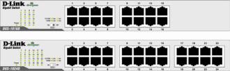
Power Input on Rear Panel
The power cable connection is located on the rear panel of the Switch.
Rear panel view of the Switch
Switch power input is provided by and internal universal power supply (100-240VAC, 50-60Hz, 0.4A Max : 12V/2A).
The AC power connector is a standard three-pronged connector that supports the power cord. Please see the Power On section below for instructions on how to properly connect the Switch to a power source.
 Kensington Security Slot
DGS-1016D/24D has been giving customers the best option for physical security through a Kensington Security Slot in the rear panel. The Kensington Security Slot adds value to DGS-1016D/24D by offering customers a simple, built-in security solution.
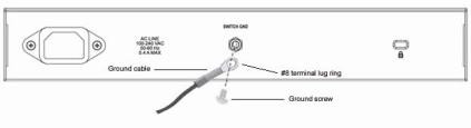
Grounding the Switch
This section describes how to connect the switch to ground. You must complete this procedure before powering your switch.
Required Tools and Equipment
Ground screws (included in the accessory kit): One M4 x 6 mm (metric) pan-head screw
10
Ground cable (not included in the accessory kit): The grounding cable should be sized according to local and national installation requirements. Depending on the power supply and system, a 12 to 6 AWG copper conductor is required for U.S installation. Commercially available 6 AWG wire is recommended. The length of the cable depends on the proximity of the switch to proper grounding facilities.
A screwdriver (not included in the accessory kit)
The following steps let you connect the switch to a protective ground:
Step 1: Verify if the system power is off.
Step 2: Use the ground cable to place the #8 terminal lug ring on top of the ground-screw opening, as seen in the figure below.
Step 3: Insert the ground screw into the ground-screw opening.
Step 4: Using a screwdriver, tighten the ground screw to secure the ground cable to the switch.
Step 5: Attach the terminal lug ring at the other end of the grounding cable to an appropriate grounding stud or bolt on rack where the switch is installed.
Step 6: Verify if the connections at the ground connector on the switch and the rack are securely attached.
11
SECTION 2
Installation
Package Contents
Before You Connect to the Network
Installing the Switch
Power On
Package Contents
Open the shipping carton of the Switch and carefully unpack its contents. The carton should contain the following items:
•One DGS-1016D 16-Port/DGS-1024D 24-Port 10/100/1000BASE-T Gigabit Ethernet Switch
•Four rubber feet with adhesive backing
•One power Cord
•Mounting ears for rack-mounting
•Quick Install Guide
If any item is found missing or damaged, please contact your local D- Link reseller for replacement.
12
Before You Connect to the Network
The site where you install the Switch may greatly affect its performance. Please follow these guidelines for setting up the Switch.
•Install the Switch on a sturdy, level surface that can support at least 3 kg (6.6 lbs) of weight. Do not place heavy objects on the Switch.
•The power outlet should be within 1.82 meters (6 feet) of the Switch.
•Visually inspect the power cord and see that it is fully secured to the AC power port.
•Make sure that there is adequate space for proper heat dissipation from and adequate ventilation around the Switch. Leave at least 10 cm (4 inches) of space at the front and rear of the Switch for ventilation.
•Do not place any device on top of Switch, or place the Switch on top of any device or object that will block the free flow of air through the ventilation slots on the sides, top, and bottom of the Switch’s case.
•Keep your hand away from top and bottom of device that generates a significant amount of heat.
•Install the Switch in a fairly cool and dry place for the acceptable temperature and humidity operating ranges.
•Install the Switch in a site free from strong electromagnetic field generators (such as motors), vibration, dust, and direct exposure to sunlight.
•When installing the Switch on a level surface, attach the rubber feet to the bottom of the device. The rubber feet cushion the Switch, protect the casing from scratches and prevent it from scratching other surfaces.
13

Mounting the Switch on a Rack
The DGS-1016D/1024D can easily be mounted on a rack. Two mounting ears are provided for this purpose. Make sure that the front panel is exposed in order to view the LEDs. Please refer to the following illustrations:
Mounting the Switch to a Rack
1.Attach the ears to each side of the Switch, using the screwholes located on the side of the device.
14
 Loading...