


Information in this document is subject to change without notice. Reproduction in any manner whatsoever, without the written permission of D-Link Corporation, is strictly forbidden.
Trademarks used in this text: D-Link and the D-LINK logo are trademarks of D-Link Corporation; Microsoft and Windows are registered trademarks of Microsoft Corporation.
Other trademarks and trade names may be used in this document to refer to either the entities claiming the marks and names or their products. D-Link Corporation disclaims any proprietary interest in trademarks and trade names other than its own.
© 2014 D-Link Corporation. All rights reserved. December, 2013 P/N 651GS1510015G
FCC Warning
This equipment has been tested and found to comply with the limits for a Class A digital device, pursuant to Part 15 of the FCC Rules. These limits are designed to provide reasonable protection against harmful interference when the equipment is operated in a commercial environment. This equipment generates, uses, and can radiate radio frequency energy and, if not installed and used in accordance with this manual, may cause harmful interference to radio communications. Operation of this equipment in a residential area is likely to cause harmful interference in which case the user will be required to correct the interference at his expense.
CE Mark Warning
This is a Class A product. In a domestic environment, this product may cause radio interference in which case the user may be required to take adequate measures.
Warnung!
Dies ist ein Produkt der Klasse A. Im Wohnbereich kann dieses Produkt Funkstoerungen verursachen. In diesem Fall kann vom Benutzer verlangt werden, angemessene Massnahmen zu ergreifen.
Precaución!
Este es un producto de Clase A. En un entorno doméstico, puede causar interferencias de radio, en cuyo case, puede requerirse al usuario para que adopte las medidas adecuadas.
Attention!
Ceci est un produit de classe A. Dans un environnement domestique, ce produit pourrait causer des interférences radio, auquel cas l`utilisateur devrait prendre les mesures adéquates.
Attenzione!
Il presente prodotto appartiene alla classe A. Se utilizzato in ambiente domestico il prodotto può causare interferenze radio, nel cui caso è possibile che l`utente debba assumere provvedimenti adeguati.
VCCI Warning
A VCCI-A
BSMI Notice
採取某些適當的對策。

DGS-1510 Series Gigabit Ethernet SmartPro Switch Hardware Installation Guide
Table of Contents
Table of Contents................................................................................................................................................................. |
iii |
|
|
Intended Readers .............................................................................................................................................................. |
v |
|
Typographical Conventions ............................................................................................................................................... |
v |
|
Notes, Notices, and Cautions ............................................................................................................................................ |
v |
|
Safety Instructions ............................................................................................................................................................ |
vi |
|
Safety Precautions....................................................................................................................................................... |
vi |
|
General Precautions for Rack-Mountable Products ......................................................................................................... |
vii |
|
Protecting Against Electrostatic Discharge...................................................................................................................... |
viii |
1. |
Introduction................................................................................................................................................................. |
9 |
|
Switch Description ............................................................................................................................................................. |
9 |
|
Package Contents.............................................................................................................................................................. |
9 |
|
Features ........................................................................................................................................................................... |
10 |
|
Front-Panel Components................................................................................................................................................. |
11 |
|
Ports............................................................................................................................................................................ |
12 |
|
LED Indicators ............................................................................................................................................................ |
13 |
|
Rear Panel Components.................................................................................................................................................. |
14 |
|
Side Panel Components .................................................................................................................................................. |
15 |
|
Smart Fans ................................................................................................................................................................. |
16 |
2. |
Installation................................................................................................................................................................. |
18 |
|
Installation Guidelines...................................................................................................................................................... |
18 |
|
Installing the Switch without a Rack ........................................................................................................................... |
18 |
|
Attaching Brackets to a Switch for Rack Mounting..................................................................................................... |
19 |
|
Installing the Switch in a Standard 19" Rack.............................................................................................................. |
19 |
|
Installing Tranceivers into the Transceiver Ports........................................................................................................ |
20 |
|
Power On (AC Power) ..................................................................................................................................................... |
20 |
|
Power Failure (AC Power) .......................................................................................................................................... |
21 |
|
Installing Power Cord Clip .......................................................................................................................................... |
21 |
3. |
Connecting the Switch ............................................................................................................................................. |
24 |
|
Switch to End Node ......................................................................................................................................................... |
24 |
|
Switch to another Switch.................................................................................................................................................. |
24 |
|
Connect to a Network Backbone or Server ..................................................................................................................... |
25 |
4. |
Introduction to Switch Management....................................................................................................................... |
26 |
|
Management Options....................................................................................................................................................... |
26 |
|
Connecting the Console Port........................................................................................................................................... |
26 |
|
Connecting to the Switch for the First Time................................................................................................................ |
27 |
|
Creating a User Account............................................................................................................................................. |
28 |
|
Configuring the IP Address......................................................................................................................................... |
29 |
|
SNMP Settings................................................................................................................................................................. |
30 |
|
Traps........................................................................................................................................................................... |
31 |
|
Management Information Base (MIB)......................................................................................................................... |
31 |
|
D-Link Network Assistant (DNA)...................................................................................................................................... |
32 |
5. |
Web-based Switch Configuration ........................................................................................................................... |
33 |
|
Introduction ...................................................................................................................................................................... |
33 |
|
Logging onto the Web Manager ...................................................................................................................................... |
33 |
|
Web-based User Interface ............................................................................................................................................... |
34 |
|
|
iii |

DGS-1510 Series Gigabit Ethernet SmartPro Switch Hardware Installation Guide |
|
Areas of the User Interface......................................................................................................................................... |
34 |
Web Pages ................................................................................................................................................................. |
35 |
Appendix A – Technical Specifications ............................................................................................................................ |
36 |
General ............................................................................................................................................................................ |
36 |
Physical and Environmental............................................................................................................................................. |
37 |
Performance..................................................................................................................................................................... |
38 |
LED Indicators ................................................................................................................................................................. |
38 |
Port Functions.................................................................................................................................................................. |
40 |
Appendix B – Cables and Connectors.............................................................................................................................. |
43 |
Ethernet Cable ................................................................................................................................................................. |
43 |
Console Cable ................................................................................................................................................................. |
44 |
Warranties & Technical Support........................................................................................................................................ |
45 |
iv

DGS-1510 Series Gigabit Ethernet SmartPro Switch Hardware Installation Guide
Intended Readers
Intended Readers
Typographical Conventions
Notes, Notices, and Cautions
Safety Instructions
General Precautions for Rack-Mountable Products
Protecting Against Electrostatic Discharge
The DGS-1510 Series Hardware Installation Guide contains information about the configuration and management of the switch. This manual is intended for network administrators familiar with network management concepts and terminology. For all practical reasons all the switches in this series will simply be referred to as the Switch throughout this manual. All example screenshots are taken from the DGS- 1510-28P switch.
Typographical Conventions
|
Convention |
|
|
Description |
|
|
|
|
|
||
|
|
|
|
|
|
[ ] |
|
|
In a command line, square brackets indicate an optional entry. For |
|
|
|
|
|
|
example: [copy filename] means that optionally you can type copy |
|
|
|
|
|
followed by the name of the file. Do not type the brackets. |
|
|
|
|
|
|
|
|
Bold Font |
|
|
Indicates a button, a toolbar icon, menu, or menu item. For example: |
|
|
|
|
|
Open the File menu and choose Cancel. Used for emphasis. May also |
|
|
|
|
|
indicate system messages or prompts appearing on screen. For |
|
|
|
|
|
example: You have mail. |
|
|
|
|
|
|
|
|
|
|
|
|
|
|
Courier New Font |
|
|
Indicates commands and responses to prompts that must be typed |
|
|
|
|
|
|
|
|
|
|
|
exactly as printed in the manual. |
|
|
|
|
|
|
|
|
Initial capital letter |
|
|
Indicates a window name. Names of keys on the keyboard have initial |
|
|
|
|
|
capitals. For example: Click Enter. |
|
|
|
|
|
|
|
|
Italics |
|
|
Indicates a window name or a field. Also can indicate a variables or |
|
|
|
|
|
parameter that is replaced with an appropriate word or string. For |
|
|
|
|
|
example: type filename means that the actual filename should be typed |
|
|
|
|
|
instead of the word shown in italic. |
|
|
|
|
|
|
|
|
Menu Name > Menu Option |
|
|
Menu Name > Menu Option indicates the menu structure. Device > |
|
|
|
|
|
Port > Port Properties means the Port Properties menu option under |
|
|
|
|
|
the Port menu option that is located under the Device menu. |
|
|
|
|
|
|
|
Notes, Notices, and Cautions
NOTE: A note indicates important information that helps you make better use of your device.
v

DGS-1510 Series Gigabit Ethernet SmartPro Switch Hardware Installation Guide
NOTICE: A notice indicates either potential damage to hardware or loss of data and tells you how to avoid the problem.
CAUTION: A caution indicates a potential for property damage, personal injury, or death.
Safety Instructions
Use the following safety guidelines to ensure your own personal safety and to help protect your system
from potential damage. Throughout this safety section, the caution icon ( ) is used to indicate precautions that need to be reviewed and followed.
Safety Precautions
To reduce the risk of bodily injury, electrical shock, fire, and damage to the equipment observe the following precautions:
•Observe and follow service markings.
•Do not service any product except as explained in the system documentation.
•Opening or removing covers that are marked with the triangular symbol with a lightning bolt may expose the user to electrical shock.
oOnly a trained service technician should service components inside these compartments.
•If any of the following conditions occur, unplug the product from the electrical outlet and replace the part or contact your trained service provider:
oDamage to the power cable, extension cable, or plug.
o An object has fallen into the product.
o The product has been exposed to water.
o The product has been dropped or damaged.
oThe product does not operate correctly when the operating instructions are correctly followed.
•Keep your system away from radiators and heat sources. Also, do not block cooling vents.
•Do not spill food or liquids on system components, and never operate the product in a wet environment. If the system gets wet, see the appropriate section in the troubleshooting guide or contact your trained service provider.
•Do not push any objects into the openings of the system. Doing so can cause fire or electric shock by shorting out interior components.
•Use the product only with approved equipment.
•Allow the product to cool before removing covers or touching internal components.
•Operate the product only from the type of external power source indicated on the electrical ratings label. If unsure of the type of power source required, consult your service provider or local power company.
•To help avoid damaging the system, be sure the voltage selection switch (if provided) on the power supply is set to match the power available at the Switch’s location:
vi

DGS-1510 Series Gigabit Ethernet SmartPro Switch Hardware Installation Guide
o115 volts (V)/60 hertz (Hz) in most of North and South America and some Far Eastern countries such as South Korea and Taiwan
o100 V/50 Hz in eastern Japan and 100 V/60 Hz in western Japan
o230 V/50 Hz in most of Europe, the Middle East, and the Far East
•Also, be sure that attached devices are electrically rated to operate with the power available in your location.
•Use only approved power cable(s). If you have not been provided with a power cable for your system or for any AC-powered option intended for your system, purchase a power cable that is approved for use in your country. The power cable must be rated for the product and for the voltage and current marked on the product's electrical ratings label. The voltage and current rating of the cable should be greater than the ratings marked on the product.
•To help prevent electric shock, plug the system and peripheral power cables into properly grounded electrical outlets. These cables are equipped with three-prong plugs to help ensure proper grounding. Do not use adapter plugs or remove the grounding prong from a cable. If using an extension cable is necessary, use a 3-wire cable with properly grounded plugs.
•Observe extension cable and power strip ratings. Make sure that the total ampere rating of all products plugged into the extension cable or power strip does not exceed 80 percent of the ampere ratings limit for the extension cable or power strip.
•To help protect the system from sudden, transient increases and decreases in electrical power, use a surge suppressor, line conditioner, or uninterruptible power supply (UPS).
•Position system cables and power cables carefully; route cables so that they cannot be stepped on or tripped over. Be sure that nothing rests on any cables.
•Do not modify power cables or plugs. Consult a licensed electrician or your power company for site modifications. Always follow your local/national wiring rules.
•When connecting or disconnecting power to hot-pluggable power supplies, if offered with your system, observe the following guidelines:
oInstall the power supply before connecting the power cable to the power supply.
o Unplug the power cable before removing the power supply.
oIf the system has multiple sources of power, disconnect power from the system by unplugging all power cables from the power supplies.
•Move products with care; ensure that all casters and/or stabilizers are firmly connected to the system. Avoid sudden stops and uneven surfaces.
General Precautions for Rack-Mountable Products
Observe the following precautions for rack stability and safety. Also, refer to the rack installation documentation accompanying the system and the rack for specific caution statements and procedures.
•Systems are considered to be components in a rack. Thus, "component" refers to any system as well as to various peripherals or supporting hardware.
CAUTION: Installing systems in a rack without the front and side stabilizers installed could cause the rack to tip over, potentially resulting in bodily injury under certain circumstances. Therefore, always install the stabilizers before installing components in the rack. After installing system/components in a rack, never pull more than one component out of the rack on its slide assemblies at one time. The weight of more than one extended component could cause the rack to tip over and may result in serious injury.
vii

DGS-1510 Series Gigabit Ethernet SmartPro Switch Hardware Installation Guide
•Before working on the rack, make sure that the stabilizers are secured to the rack, extended to the floor, and that the full weight of the rack rests on the floor. Install front and side stabilizers on a single rack or front stabilizers for joined multiple racks before working on the rack.
•Always load the rack from the bottom up, and load the heaviest item in the rack first.
•Make sure that the rack is level and stable before extending a component from the rack.
•Use caution when pressing the component rail release latches and sliding a component into or out of a rack; the slide rails can pinch your fingers.
•After a component is inserted into the rack, carefully extend the rail into a locking position, and then slide the component into the rack.
•Do not overload the AC supply branch circuit that provides power to the rack. The total rack load should not exceed 80 percent of the branch circuit rating.
•Ensure that proper airflow is provided to components in the rack.
•Do not step on or stand on any component when servicing other components in a rack.
NOTE: A qualified electrician must perform all connections to DC power and to safety grounds. All electrical wiring must comply with applicable local or national codes and practices.
CAUTION: Never defeat the ground conductor or operate the equipment in the absence of a suitably installed ground conductor. Contact the appropriate electrical inspection authority or an electrician if uncertain that suitable grounding is available.
CAUTION: The system chassis must be positively grounded to the rack cabinet frame. Do not attempt to connect power to the system until grounding cables are connected. Completed power and safety ground wiring must be inspected by a qualified electrical inspector. An energy hazard will exist if the safety ground cable is omitted or disconnected.
Protecting Against Electrostatic Discharge
Static electricity can harm delicate components inside the system. To prevent static damage, discharge static electricity from your body before touching any of the electronic components, such as the microprocessor. This can be done by periodically touching an unpainted metal surface on the chassis.
The following steps can also be taken prevent damage from electrostatic discharge (ESD):
1.When unpacking a static-sensitive component from its shipping carton, do not remove the component from the antistatic packing material until ready to install the component in the system. Just before unwrapping the antistatic packaging, be sure to discharge static electricity from your body.
2.When transporting a sensitive component, first place it in an antistatic container or packaging.
3.Handle all sensitive components in a static-safe area. If possible, use antistatic floor pads, workbench pads and an antistatic grounding strap.
viii

DGS-1510 Series Gigabit Ethernet SmartPro Switch Hardware Installation Guide
1. Introduction
Switch Description
Package Contents
Features
Front-Panel Components
Rear Panel Components
Side Panel Components
This Hardware Installation Guide is a detailed document explaining information about the hardware installation, configuration, specifications, guidelines, and maintenance of a D-Link switch.
Switch Description
The DGS-1510 Series is D-Link’s next generation SmartPro Switch. It features built-in 10Gbps SFP+ ports targeted for SME/SMB core deployment to improve connectivity between core switches and edge switches. The DGS-1510 Series also implements D-Link’s innovative 3rd generation Green Ethernet technology (IEEE 802.3az) by not only saving power over inactive links, but also turning off LEDs on a customized schedule and allowing ports to enter a hibernative state automatically.
In the DGS-1510 Series, the following switches are available: DGS-1510-20, DGS-1510-28, DGS-1510- 28P, and DGS-1510-52. Some features, throughout this guide, will apply to all the switches within the DGS-1510 Series. When referring to these universal features, we’ll simply refer to the product as the
Switch.
Package Contents
When purchasing a D-Link DGS-1510 Series Switch, a list of items will be included in the package of the Switch. Open the shipping carton of the Switch and carefully unpack its contents. The carton should contain the following items:
•One D-Link DGS-1510 Series Switch.
•One Quick Installation Guide.
•One AC power cord.
•One console cable.
•One power cord cable clip.
•One mounting mit (two brackets and screws).
•Four rubber feet with adhesive backing.
•One CD that includes a digital copy of the CLI Reference Guide, Web UI Reference Guide, Hardware Installation Guide, D-View module, D-Link Network Assistant, and D-Link Network Assistant Guide.
NOTE: If any item is missing or damaged, please contact your local D-Link Reseller for replacement.
9

DGS-1510 Series Gigabit Ethernet SmartPro Switch Hardware Installation Guide
Features
The list of features below highlights the significant features of the Switch.
•Supports Virtual Stacking. D-Link Single IP Management (SIM).
•Supports Physical Stacking, using the SFP+ ports with 40G (Full Duplex) in topologies Linear and Ring.
•Supports a 16K MAC address table.
•Supports Flow Control (802.3x) in full-duplex compliant.
•Supports Jumbo Frames of up to 9Kbytes
•Supports Spanning Tree with 802.1D 2004 STP/RSTP and 802.1Q 2005 MSTP.
•Supports Loopback Detection (LBD).
•Supports Link Aggregation (802.3ad and 802.3AX) with a maximum of 32 groups per Switch.
•Supports Port Mirroring.
•Supports Layer 2 Multicast Filtering.
•Supports IGMP Snooping (v1, v2, v3 awareness) with up to 512 snooping groups and 128 static multicast addresses. MLD Snooping (v1, v2 awareness) with up to 512 snooping groups and 128 static multicast addresses. IGMP Snooping and MLD Snooping share 128 static groups and 512 snooping groups.
•Supports Virtual LAN (802.1Q) with up to 4K static VLAN groups and 4K dynamic VLAN groups.
•Supports Port-based VLAN.
•Supports Asymmetric VLAN.
•Supports Auto Voice and Surveillance VLAN.
•Supports IP Interfaces with up to 8 IP interfaces.
•Supports Gratuitous ARP.
•Supports IPv6 Ready Phase 2 compliancy.
•Supports Static Routing.
•Supports Quality of Service (QoS) with Queue Handling and Class of Service (CoS).
•Supports Access Control List (ACL) with Ingress ACL, Time-based ACL, and ACL Statistics.
•Supports Secure Shell (SSHv2) with IPv4/IPv6 access.
•Supports Secure Sockets Layer (SSL) versions 1, 2, and 3 with IPv4/IPv6 access.
•Supports Port Security of up to 128 MAC addresses.
•Supports Broadcast and Multicast Storm Control.
•Supports Traffic Segmentation
•Supports D-Link SafeGuard Engine.
•Supports ARP Spoofing Prevention.
•Supports IP-MAC-Port Binding (IMPB). This feature includes DHCP Snooping, IP Source Guard, Dynamic ARP Inspection, DHCPv6 Guard, RA Guard, IPv6 Snooping, IPv6 Source Guard, and IPv6 ND Snooping.
•Supports DoS Attack Prevention.
10
DGS-1510 Series Gigabit Ethernet SmartPro Switch Hardware Installation Guide
•Supports Port-based Network Access Control (PNAC) better known as 802.1X. This feature includes Local and RADIUS databasis, Port-based Access Control, and MAC-based Access Control (MAC).
•Supports Web-based Access Control (WAC).
•Supports Japanese Web-based Access Control (JWAC).
•Supports Guest VLAN.
•Supports 15 User Account Privilege Levels.
•Supports Compound Authentication.
•Supports Link Layer Discovery Protocol (LLDP) with LLDP-MED.
•Supports Accessibility using multiple interfaces like the Command Line Interface (CLI), Webbased Graphical User Interface (Web-based GUI), and more.
•Supports Telnet Server and Client from IPv4 and IPv6.
•Supports Trivial File Transfer Protocol (TFTP) Client.
•Supports Simple Network Management Protocol (SNMP) version 1, 2c, and 3. Also supports SNMP Traps.
•Supports DHCP Client.
•Supports Dynamic Host Configuration Protocol (DHCP) Relay.
•Supports Traps and Logs.
•Support Multiple Images.
•Supports Password Encryption.
•Supports Simple Network Time Protocol (SNTP).
•Support Power Saving using the Link Status Mode.
•Support Time-based Power-over-Ethernet (PoE).
•Supports IEEE 802.3az compliance.
•Supports Optical Transceiver Digital Diagnostic Monitoring (DDM).
•Supports D-Link Discovery Protocol (DDP).
•Supports MIBs like MIBII, Bridge MIB, SNMPv2 MIB, RMON MIB, RMONv2 MIB, Ether-like MIB, 802.3 MAU MIB, 802.1p MIB, RADIUS Authentication Client MIB, Ping MIB, L2 Specific MIB, Private MIB, Entity MIB, and ZoneDefense MIB.
Front-Panel Components
The Front Panel of the Switch features a variety of Ports and LED Indicators that will be discussed in detail in this section. Also located on the front panel of the Switch is a Reset button, that can be pressed and holded for 5 seconds to perform a factory reset on the Switch after which the Switch will reboot. This will clear all the software modifications done on the Switch to their factory default settings.
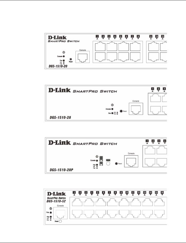
Figure 1–1 Front panel view of a DGS-1510-20 Switch
11
DGS-1510 Series Gigabit Ethernet SmartPro Switch Hardware Installation Guide
Figure 1–2 Front panel view of a DGS-1510-28 Switch
Figure 1–3 Front panel view of a DGS-1510-28P Switch
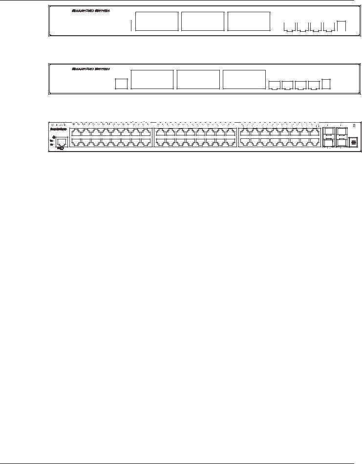
Figure 1–4 Front panel view of a DGS-1510-52 Switch
Ports
The Type and Number of ports available on the Switch are listed out below:
•DGS-1510-20:
oSixteen Copper Ports (10BASE-T/100BASE-TX/1000BASE-T),
oTwo SFP Ports (1000BASE),
oTwo Dual Speed SFP+ Ports (1000BASE/10GBASE),
oOne Console Port (RJ-45),
•DGS-1510-28:
oTwenty-four Copper Ports (10BASE-T/100BASE-TX/1000BASE-T),
oTwo SFP Ports (1000BASE),
oTwo Dual Speed SFP+ Ports (1000BASE/10GBASE),
oOne Console Port (RJ-45),
•DGS-1510-28P:
oTwenty-four Copper PoE Ports (10BASE-T/100BASE-TX/1000BASE-T),
oTwo SFP Ports (1000BASE),
oTwo Dual Speed SFP+ Ports (1000BASE/10GBASE),
oOne Console Port (RJ-45),
•DGS-1510-52:
oFourty-eight Copper Ports (10BASE-T/100BASE-TX/1000BASE-T),
o Two SFP Ports (1000BASE),
o Two Dual Speed SFP+ Ports (1000BASE/10GBASE),
o One Console Port (RJ-45),
12
DGS-1510 Series Gigabit Ethernet SmartPro Switch Hardware Installation Guide
LED Indicators
The Switch’s front panel presents LED indicators for Power, Console, Master (Stack Control), Stack ID and Link/Act indicators for all the ports. The DGS-1510-28P switches are equipt with an additional PoE light, to indication whether the ports are running in Power over Ethernet mode.
Figure 1–5 LED indicators for a DGS-1510-20 Switch
Figure 1–6 LED indicators for a DGS-1510-28 Switch
Figure 1–7 LED indicators for a DGS-1510-28P Switch
Figure 1–8 LED indicators for a DGS-1510-52 Switch
13

DGS-1510 Series Gigabit Ethernet SmartPro Switch Hardware Installation Guide
A separate table below describes LED indicators in more detail.
LED |
Description |
|
|
Power |
This LED will light green after powering the Switch on to indicate the |
|
ready state of the device. The indicator is dark when the Switch is no |
|
longer receiving power (i.e. powered off). |
|
|
Console |
This LED will blink green during the Power-On Self Test (POST). |
|
When the POST is finished, the LED goes dark. The indicator will light |
|
steady green when a user is logged in through the console port. |
|
|
Fan |
This LED will light green after the diagnostics have passed with no |
|
errors. This LED blinks red when any of the fans has failed. |
|
|
Link/Act LEDs |
The Switch has LED indicators for Link and Activity. |
|
Copper Ports: The LED will light steady green when there is a secure |
|
connection (or link) to a 1000Mbps Ethernet device or steady orange |
|
when there is a secure connection (or link) to a 10/100Mbps Ethernet |
|
device at any of the copper ports. The LED will blink green when a |
|
1000Mbps port is active or blink orange when a 10/100Mbps port is |
|
active. The LED remains dark when there is no link or activity. |
|
SFP Ports: The LED will light steady green when there is a secure |
|
connection (or link) to a 1000Mbps Ethernet device at any of the SFP |
|
ports. The LED remains dark when there is no link or activity. |
|
SFP+ Ports: The LED will light steady green when there is a secure |
|
connection (or link) to a 10Gbps Ethernet device or steady orange |
|
when there is a secure connection (or link) to a 1Gbps Ethernet device |
|
at any of the SFP+ ports. The LED will blink green when a 10Gbps |
|
port is active or blink orange when a 1Gbps port is active. The LED |
|
remains dark when there is no link or activity. |
|
|
PoE |
Only the DGS-1510-28P switches are equipt with a PoE LED. When |
|
this light is on with a solid green light, it means that the corresponding |
|
ports are feeding power to the PoE devices plugged in. When this light |
|
is on with a solid orange light, it means that the port is in an error |
|
condition state. When this light is off, it means that the ports are not |
|
supplying power to the devices plugged into the ports. |
|
|
Stack ID |
For standalone Switches, this will display number “1”. For stacked |
|
Switches, this indicates the position in the stacking box ID. The box ID |
|
is assigned either by the user (static mode) or by the system |
|
(automatic mode). When “1” to “6” is displayed, this indicates the |
|
stacking position of the switch. An “H” indicates the device was |
|
assigned as the stacking Master. “h“ means the device was selected to |
|
be the Backup Master. A “G” is displayed when the Safeguard Engine |
|
feature enters the exhausted mode. An “E” is displayed when an error |
|
was found during the system self-test. |
|
|
For more information about LED Indicators, refer to LED Indicators.
Rear Panel Components
The rear panel contains an AC power socket and a security lock.
14
DGS-1510 Series Gigabit Ethernet SmartPro Switch Hardware Installation Guide
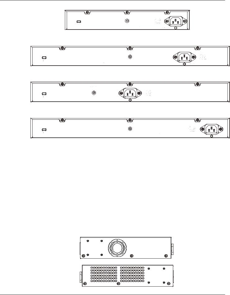
Figure 1–9 Rear panel view of a DGS-1510-20 Switch
Figure 1–10 Rear panel view of a DGS-1510-28 Switch
Figure 1–11 Rear panel view of a DGS-1510-28P Switch
Figure 1–12 Rear panel view of a DGS-1510-52 Switch
The AC power connector is a standard three-pronged connector that supports the power cord. Plug-in the female connector of the provided power cord into this socket, and the male side of the cord into a power outlet. The Switch automatically adjusts the power setting to any supply voltage in the range from 100~240 VAC at 50~60 Hz.
Side Panel Components
The system heat vents located on the sides of the Switch dissipate heat. Do not block these openings. Leave at least 6 inches of space at the rear and sides of the Switch for proper ventilation. Without proper heat dissipation and air circulation, system components might overheat which could lead to system failure or even severely damaged components.
15

DGS-1510 Series Gigabit Ethernet SmartPro Switch Hardware Installation Guide
Figure 1–13 Side panels view of a DGS-1510-20 Switch
Figure 1–14 Side panels view of a DGS-1510-28 Switch
Figure 1–15 Side panels view of a DGS-1510-28P Switch
Figure 1–16 Side panels view of a DGS-1510-52 Switch
Smart Fans
The DGS-1510 Series Switches includes smart fans that will automatically change their speed depending on the internal temperature detected by the sensors built-in the Switch’s hardware. These smart fans support three states. They can either be off, running at a low speed, or running at a high speed.
The following will explain when these fans will toggle between low and high speeds:
•DGS-1510-20: When the internal temperature, detected by the sensor, rises above 47°C, the fan will automatically change to the high speed. When the internal temperature, detected by the sensor, falls below 43°C, the fan will automatically change to the low speed.
•DGS-1510-28: When the internal temperature, detected by the sensor, rises above 48°C, the fan will automatically change to the high speed. When the internal temperature, detected by the sensor, falls below 43°C, the fan will automatically change to the low speed.
16

DGS-1510 Series Gigabit Ethernet SmartPro Switch Hardware Installation Guide
•DGS-1510-28P: When the internal temperature, detected by the sensor, rises above 42°C, the fan will automatically change to the high speed. When the internal temperature, detected by the sensor, falls below 39°C, the fan will automatically change to the low speed.
•DGS-1510-52: When the internal temperature, detected by the sensor, rises above 47°C, the fan will automatically change to the high speed. When the internal temperature, detected by the sensor, falls below 43°C, the fan will automatically change to the low speed.
17
DGS-1510 Series Gigabit Ethernet SmartPro Switch Hardware Installation Guide
2. Installation
Installation Guidelines
Power On (AC Power)
Installation Guidelines
Please follow these guidelines for setting up the Switch:
•Install the Switch on a sturdy, level surface that can support at least 3kg (6.6lb). Do not place heavy objects on the Switch.
•The power outlet should be within 1.82 meters (6 feet) of the Switch.
•Visually inspect the power cord and see that it is fully secured to the AC power port.
•Make sure that there is proper heat dissipation from and adequate ventilation around the Switch. Leave at least 10 cm (4 inches) of space at the front and rear of the Switch for ventilation.
•Install the Switch in a fairly cool and dry place for the acceptable temperature and humidity operating ranges.
•Install the Switch in a site free from strong electromagnetic field generators (such as motors), vibration, dust, and direct exposure to sunlight.
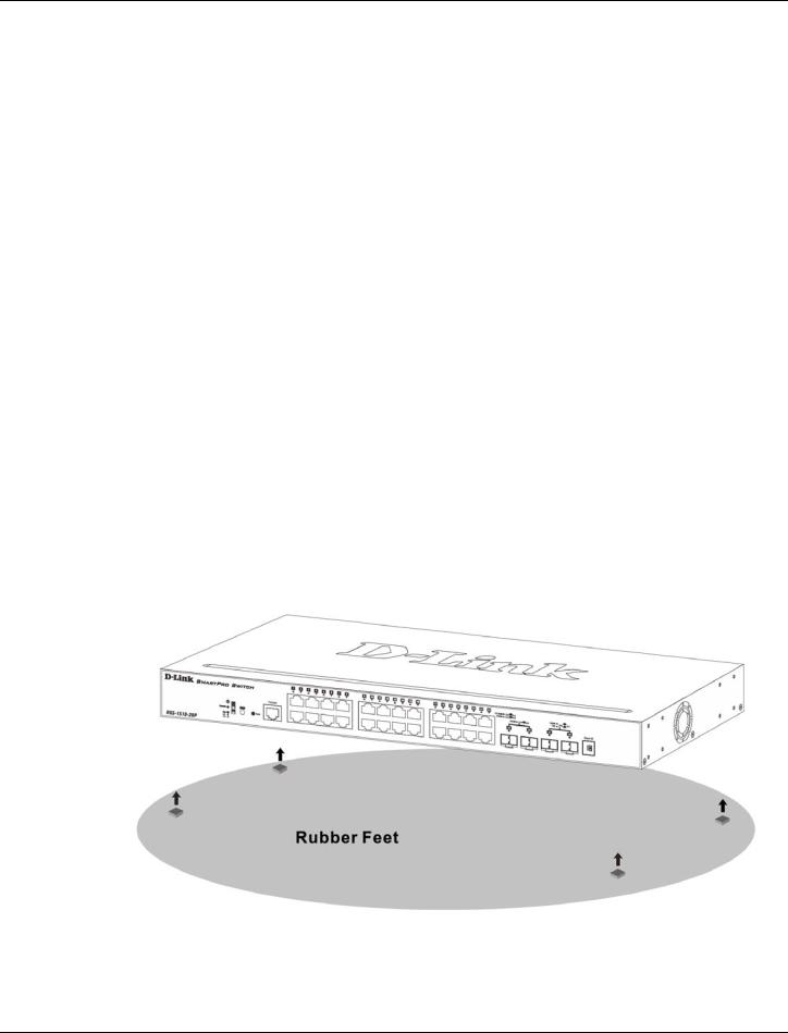
•When installing the Switch on a level surface, attach the rubber feet to the bottom of the device. The rubber feet cushion the Switch, protect the casing from scratches and prevent it from scratching other surfaces.
Installing the Switch without a Rack
First, attach the rubber feet included with the Switch if installing on a desktop or shelf. Attach these cushioning feet on the bottom at each corner of the device. Allow enough ventilation space between the Switch and any other objects in the vicinity.
Figure 2–1 Attach rubber feet to the Switch.
18
DGS-1510 Series Gigabit Ethernet SmartPro Switch Hardware Installation Guide
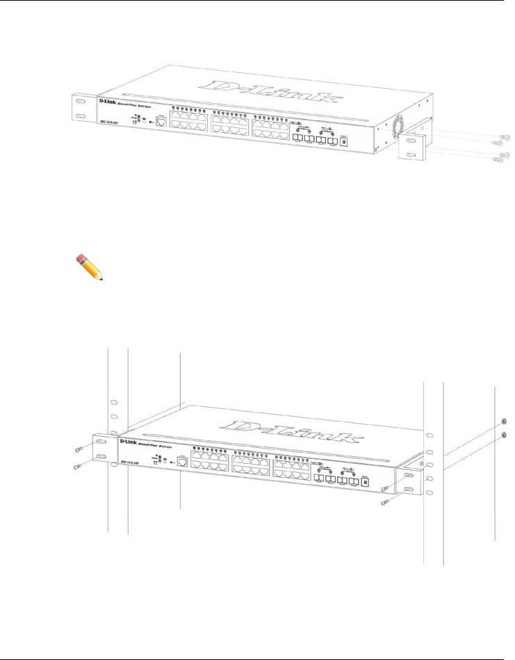
Attaching Brackets to a Switch for Rack Mounting
The Switch is mounted to a standard 19" rack using mounting brackets. Use the following diagrams as a guide.
Figure 2–2 Attach mounting brackets to the Switch
Fasten the mounting brackets to the Switch using the screws provided. With the brackets attached securely, the Switch can be mounted in a standard rack, as shown below.
NOTE: Please review the Installation Guidelines above before installing the Switch in a rack. Make sure there is adequate space around the Switch to allow for proper air flow, ventilation and cooling.
Installing the Switch in a Standard 19" Rack
Figure 2–3 Mount the Switch in a rack
19
DGS-1510 Series Gigabit Ethernet SmartPro Switch Hardware Installation Guide
CAUTION: Installing systems in a rack without the front and side stabilizers installed could cause the rack to tip over, potentially resulting in bodily injury under certain circumstances. Therefore, always install the stabilizers before installing components in the rack. After installing components in a rack, do not pull more than one component out of the rack on its slide assemblies at one time. The weight of more than one extended component could cause the rack to tip over and may result in injury.
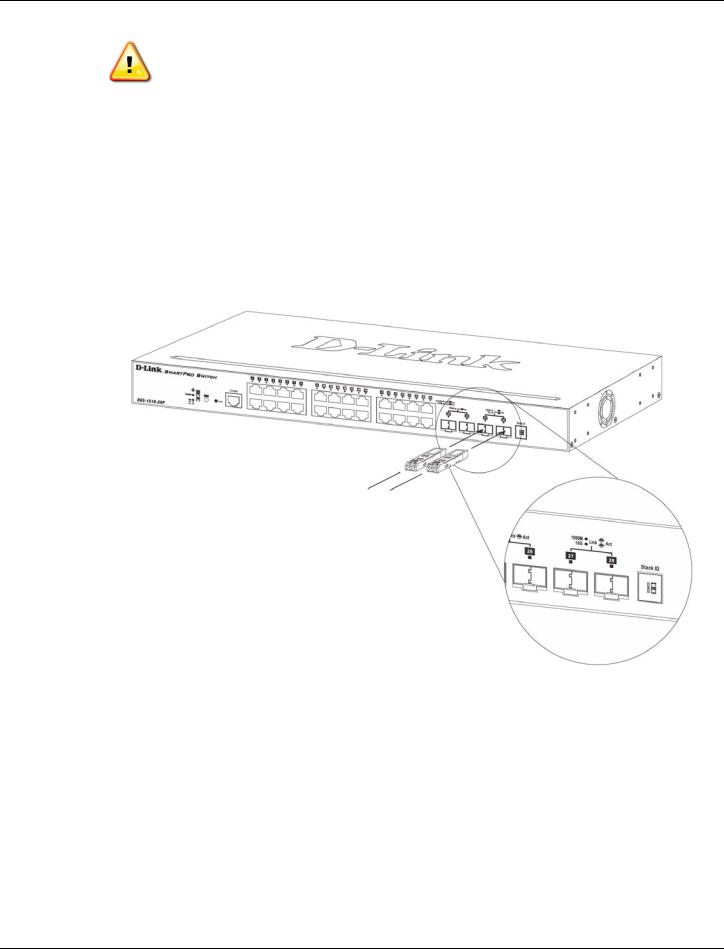
Installing Tranceivers into the Transceiver Ports
The Switch is equipped with SFP (Small Form Factor Portable) and SFP+ ports, which are used with fiber-optical transceiver cabling.SFP ports support full-duplex transmissions, auto-negotiation, and can be uplinked with various other switches across a gigabit network. The SFP ports support data rates of up to 1Gbit/s and the SFP+ ports support data rates of up to 10Gbit/s.
See the figure below for installing the transceiver in the transceiver port on the Switch.
Figure 2–4 Inserting fiber-optic transceivers into a Switch
For a full list of supported transceivers, compatible with this switch series, refer to Port Functions.
Power On (AC Power)
Plug one end of the AC power cord into the power socket of the Switch and the other end into the local power source outlet. After the system powered on, the LED’s blink green to indicate that the system is booting up.
20
 Loading...