


 Loading...
Copyright and Trademarks
Information in this document is subjected to change without notice. © 2013 D-Link Corporation. All rights reserved.
Reproduction in any manner whatsoever without the written permission of D-Link Corporation is strictly forbidden.
Trademarks used in this text: D-Link and the D-LINK logo are trademarks of D-Link Corporation; Microsoft and Windows are registered trademarks of Microsoft Corporation.
Other trademarks and trade names may be used in this document to refer to either the entities claiming the marks and names or their products. D-Link Corporation disclaims any proprietary interest in trademarks and trade names other than its own.
CE Mark Warning
This is a Class A product. In a domestic environment, this product may cause radio interference in which case the user may be required to take adequate measures.
Warnung!
Dies ist ein Produkt der Klasse A. Im Wohnbereich kann dieses Produkt Funkstoerungen verursachen. In diesem Fall kann vom Benutzer verlangt werden, angemessene Massnahmen zu ergreifen.
Precaución!
Este es un producto de Clase A. En un entorno doméstico, puede causar interferencias de radio, en cuyo case, puede requerirse al usuario para que adopte las medidas adecuadas.
Attention!
Ceci est un produit de classe A. Dans un environnement domestique, ce produit pourrait causer des interférences radio, auquel cas l`utilisateur devrait prendre les mesures adéquates.
Attenzione!
Il presente prodotto appartiene alla classe A. Se utilizzato in ambiente domestico il prodotto può causare interferenze radio, nel cui caso è possibile che l`utente debba assumere provvedimenti adeguati.
SFP (Mini-GBIC), XENPAK, and XFP Regulatory Compliance
Networks pluggable optical modules meet the following regulatory requirements: UL recognized Optical Transceiver product, Rated Laser Class I. 3.3Vdc. EN60825-1:2007 2nd Ed. or later, European standard.
FCC 21 CFR Chapter 1, Subchapter J in accordance with FDA & CDRH requirements. 47 CFR Part 15, Class A.
Application of CE Mark in accordance with 2004/108/EEC EMC Directive and the 2006/95/EC Low Voltage Directives.

Table of Contents |
D-Link Web Smart Switch User Manual |
Table of Contents |
|
Table of Contents ............................................................................................................................................. |
i |
Intended Readers............................................................................................................................................. |
1 |
Terms/Usage.................................................................................................................................................. |
1 |
Safety Instructions.......................................................................................................................................... |
1 |
General Precautions for Rack-Mountable Products ...................................................................................... |
2 |
Protecting Against Electrostatic Discharge.................................................................................................... |
3 |
Product Introduction................................................................................................................................ |
4 |
DGS-1210-08P............................................................................................................................................... |
5 |
Front Panel ................................................................................................................................................. |
5 |
Rear Panel.................................................................................................................................................. |
5 |
DGS-1210-16 ................................................................................................................................................. |
6 |
Front Panel ................................................................................................................................................. |
6 |
Rear Panel.................................................................................................................................................. |
6 |
DGS-1210-24 ................................................................................................................................................. |
6 |
Front Panel ................................................................................................................................................. |
6 |
Rear Panel.................................................................................................................................................. |
7 |
DGS-1210-24P............................................................................................................................................... |
7 |
Front Panel ................................................................................................................................................. |
7 |
Rear Panel.................................................................................................................................................. |
8 |
DGS-1210-48 ................................................................................................................................................. |
8 |
Front Panel ................................................................................................................................................. |
8 |
Rear Panel.................................................................................................................................................. |
8 |
Hardware Installation ............................................................................................................................... |
9 |
Step 1: Unpacking.......................................................................................................................................... |
9 |
Step 2: Switch Installation.............................................................................................................................. |
9 |
Desktop or Shelf Installation....................................................................................................................... |
9 |
Rack Installation ......................................................................................................................................... |
9 |
Step 3: Plugging in the AC Power Cord with Power Cord Clip.................................................................... |
10 |
Power Failure ........................................................................................................................................... |
13 |
Getting Started........................................................................................................................................ |
14 |
Management Options................................................................................................................................... |
14 |
Using Web-based Management .................................................................................................................. |
14 |
Supported Web Browsers ........................................................................................................................ |
14 |
Connecting to the Switch.......................................................................................................................... |
14 |
Login Web-based Management ............................................................................................................... |
15 |
Smart Wizard ............................................................................................................................................... |
15 |
Web-based Management............................................................................................................................. |
15 |
D-Link Network Assistant (DNA).................................................................................................................. |
15 |
Configuration .......................................................................................................................................... |
17 |
Smart Wizard Configuration......................................................................................................................... |
17 |
IP Information ........................................................................................................................................... |
17 |
Password.................................................................................................................................................. |
18 |
SNMP ....................................................................................................................................................... |
19 |
Web-based Management............................................................................................................................. |
20 |
Tool Bar > Save Menu ................................................................................................................................. |
21 |
Save Configuration................................................................................................................................... |
21 |
Save Log .................................................................................................................................................. |
21 |
i |
|
Table of Contents |
D-Link Web Smart Switch User Manual |
Tool Bar > Tools Menu................................................................................................................................. |
21 |
|
Reset ........................................................................................................................................................ |
21 |
|
Reset System ........................................................................................................................................... |
21 |
|
Reboot Device .......................................................................................................................................... |
22 |
|
Configuration Backup and Restore .......................................................................................................... |
22 |
|
Firmware Backup and Upgrade................................................................................................................ |
22 |
|
Language Management ........................................................................................................................... |
23 |
|
Tool Bar > Smart Wizard.............................................................................................................................. |
24 |
|
Tool Bar > Online Help................................................................................................................................. |
24 |
|
Function Tree ............................................................................................................................................... |
25 |
|
Device Information.................................................................................................................................... |
25 |
|
System > System Settings ....................................................................................................................... |
26 |
|
System > Password.................................................................................................................................. |
27 |
|
System > Port Settings............................................................................................................................. |
27 |
|
System > DHCP Auto Configuration ........................................................................................................ |
29 |
|
System > SysLog Host ............................................................................................................................. |
29 |
|
System > Time Profile .............................................................................................................................. |
29 |
|
System > Power Saving ........................................................................................................................... |
30 |
|
System > IEEE802.3az EEE Settings ...................................................................................................... |
31 |
|
System > DNS Resolver Settings ............................................................................................................ |
32 |
|
VLAN > 802.1Q VLAN.............................................................................................................................. |
32 |
|
VLAN > 802.1Q VLAN PVID .................................................................................................................... |
33 |
|
VLAN > 802.1Q Management VLAN........................................................................................................ |
33 |
|
VLAN > Voice VLAN > Voice VLAN Global Settings ............................................................................... |
33 |
|
VLAN > Voice VLAN > Voice VLAN Port Settings ................................................................................... |
35 |
|
VLAN > Voice VLAN > Voice Device List................................................................................................. |
36 |
|
VLAN > Auto Surveillance VLAN ............................................................................................................. |
36 |
|
L2 |
Functions > Jumbo Frame................................................................................................................... |
37 |
L2 |
Functions > Port Mirroring................................................................................................................... |
37 |
L2 |
Functions > Loopback Detection......................................................................................................... |
38 |
L2 |
Functions > MAC Address Table > Static MAC .................................................................................. |
39 |
L2 |
Functions > MAC Address Table > Dynamic Forwarding Table ......................................................... |
39 |
L2 |
Functions > Spanning Tree > STP Global Settings ............................................................................ |
40 |
L2 |
Functions > Spanning Tree > STP Port Settings ................................................................................ |
41 |
L2 |
Functions > Link Aggregation > Port Trunking.................................................................................... |
43 |
L2 |
Functions > Link Aggregation > LACP Port Settings .......................................................................... |
43 |
L2 |
Functions > Multicast > IGMP Snooping............................................................................................. |
44 |
L2 |
Functions > Multicast > MLD Snooping .............................................................................................. |
46 |
L2 |
Functions > Multicast > Multicast Forwarding ..................................................................................... |
48 |
L2 |
Functions > Multicast > Multicast Filtering Mode ................................................................................ |
49 |
L2 |
Functions > SNTP > Time Settings ..................................................................................................... |
49 |
L2 |
Functions > SNTP > Time Zone Settings............................................................................................ |
50 |
L2 |
Functions > LLDP > LLDP Global Settings ......................................................................................... |
51 |
L2 |
Functions > LLDP > LLDP MED Settings (DGS-1210-24P only)........................................................ |
51 |
L2 |
Functions > LLDP > LLDP Port Settings............................................................................................. |
52 |
L2 |
Functions > LLDP > 802.1 Extension TLV .......................................................................................... |
52 |
L2 |
Functions > LLDP > 802.3 Extension TLV .......................................................................................... |
53 |
L2 |
Functions > LLDP > LLDP Management Address Settings ................................................................ |
54 |
L2 Functions > LLDP > LLDP Management Address Table .................................................................... |
55 |
|
|
ii |
|

Table of Contents |
D-Link Web Smart Switch User Manual |
L2 Functions > LLDP > LLDP Local Port Table ....................................................................................... |
56 |
L2 Functions > LLDP > LLDP Remote Port Table ................................................................................... |
57 |
L2 Functions > LLDP > LLDP Statistics ................................................................................................... |
59 |
L3 Functions > IPv6 System Settings ...................................................................................................... |
61 |
L3 Functions > IPv6 Route Settings......................................................................................................... |
61 |
L3 Functions > IPv6 Neighbor Settings.................................................................................................... |
62 |
L3 Functions > DHCP > DHCP Relay Settings........................................................................................ |
62 |
L3 Functions > DHCP > DHCPv6 Relay Settings .................................................................................... |
63 |
QoS > Bandwidth Control......................................................................................................................... |
64 |
QoS > 802.1p/DSCP/ToS......................................................................................................................... |
65 |
QoS > IPv6 Traffic Class Priority Settings................................................................................................ |
66 |
QoS > TCP/UDP Port Priority Settings .................................................................................................... |
66 |
Security > Trusted Host............................................................................................................................ |
66 |
Security > Port Security............................................................................................................................ |
67 |
Security > DoS Attack Prevention ............................................................................................................ |
68 |
Security > Traffic Segmentation ............................................................................................................... |
69 |
Security > Safeguard Engine.................................................................................................................... |
69 |
Security > Storm Control .......................................................................................................................... |
70 |
Security > ARP Spoofing Prevention ....................................................................................................... |
70 |
Security > DHCP Server Screening ......................................................................................................... |
71 |
Security > SSL.......................................................................................................................................... |
72 |
Security > Smart Binding > Smart Binding Settings................................................................................. |
72 |
Security > Smart Binding > Smart Binding............................................................................................... |
73 |
Security > Smart Binding > White List...................................................................................................... |
74 |
Security > Smart Binding > Black List ...................................................................................................... |
74 |
AAA > 802.1X > 802.1X Settings ............................................................................................................. |
75 |
AAA > 802.1X > Guest VLAN Settings..................................................................................................... |
77 |
AAA > 802.1X > RADIUS > RADIUS Server Settings ............................................................................. |
77 |
ACL > ACL Wizard ................................................................................................................................... |
78 |
ACL > Access Profile List ......................................................................................................................... |
79 |
ACL > ACL Finder .................................................................................................................................... |
91 |
PoE > PoE Global Settings (DGS-1210-08P/24P only) ........................................................................... |
92 |
PoE > PoE Port Settings (DGS-1210-08P/24P only)............................................................................... |
92 |
SNMP > SNMP > SNMP Global Settings ................................................................................................ |
93 |
SNMP > SNMP > SNMP User ................................................................................................................. |
94 |
SNMP > SNMP > SNMP Group ............................................................................................................... |
95 |
SNMP > SNMP > SNMP View ................................................................................................................. |
95 |
SNMP > SNMP > SNMP Community....................................................................................................... |
96 |
SNMP > SNMP > SNMP Host.................................................................................................................. |
96 |
SNMP > SNMP > SNMP Engine ID ......................................................................................................... |
97 |
SNMP > RMON > RMON Global Settings ............................................................................................... |
97 |
SNMP > RMON > RMON Statistics ......................................................................................................... |
97 |
SNMP > RMON > RMON History............................................................................................................. |
98 |
SNMP > RMON > RMON Alarm .............................................................................................................. |
98 |
SNMP > RMON > RMON Event............................................................................................................... |
99 |
Monitoring > Port Statistics....................................................................................................................... |
99 |
Monitoring > Cable Diagnostics ............................................................................................................. |
101 |
Monitoring > System Log........................................................................................................................ |
102 |
Command Line Interface ..................................................................................................................... |
103 |
iii |
|
Table of Contents |
D-Link Web Smart Switch User Manual |
To connect a switch via TELNET:.............................................................................................................. |
103 |
To connect a switch via SSH: .................................................................................................................... |
103 |
Logging on to the Command Line Interface:.............................................................................................. |
103 |
CLI Commands: ......................................................................................................................................... |
103 |
?.............................................................................................................................................................. |
104 |
download ................................................................................................................................................ |
105 |
upload..................................................................................................................................................... |
106 |
config ipif System ................................................................................................................................... |
107 |
logout...................................................................................................................................................... |
107 |
ping......................................................................................................................................................... |
108 |
ping6....................................................................................................................................................... |
109 |
reboot ..................................................................................................................................................... |
109 |
reset config ............................................................................................................................................. |
110 |
show ipif.................................................................................................................................................. |
110 |
show switch ............................................................................................................................................ |
111 |
config account admin password ............................................................................................................. |
111 |
save ........................................................................................................................................................ |
112 |
debug info............................................................................................................................................... |
112 |
Appendix A - Ethernet Technology............................................................................................................ |
114 |
Gigabit Ethernet Technology ..................................................................................................................... |
114 |
Fast Ethernet Technology.......................................................................................................................... |
114 |
Switching Technology ................................................................................................................................ |
114 |
Appendix B - Technical Specifications ..................................................................................................... |
115 |
Hardware Specifications ............................................................................................................................ |
115 |
Key Components / Performance ............................................................................................................ |
115 |
Port Functions ........................................................................................................................................ |
115 |
Physical & Environment ......................................................................................................................... |
115 |
Emission (EMI) Certifications ................................................................................................................. |
115 |
Safety Certifications................................................................................................................................ |
115 |
Features ..................................................................................................................................................... |
115 |
L2 Features ............................................................................................................................................ |
115 |
L3 Features ............................................................................................................................................ |
116 |
VLAN ...................................................................................................................................................... |
116 |
QoS (Quality of Service)......................................................................................................................... |
116 |
AAA ........................................................................................................................................................ |
116 |
ACL......................................................................................................................................................... |
116 |
Security................................................................................................................................................... |
116 |
Smart Binding ......................................................................................................................................... |
116 |
OAM ....................................................................................................................................................... |
116 |
Management........................................................................................................................................... |
116 |
D-Link Green Technology ...................................................................................................................... |
116 |
iv
Intended Readers |
D-Link Web Smart Switch User Manual |
Intended Readers
This guide provides instructions to install the D-Link Gigabit Web Smart Switch DGS-1210-08P/16/24/24P/48, how to configure Web-based Management step-by-step.
NOTE: The model you have purchased may appear slightly different from the illustrations shown in the document. Refer to the Product Instruction and Technical Specification sections for detailed information about your switch, its components, network connections, and technical specifications.
This guide is mainly divided into three parts:
1.Hardware Installation: Step-by-step hardware installation procedures.
2.Getting Started: A startup guide for basic switch installation and settings.
3.Configuration: Information about the function descriptions and configuration settings.
Terms/Usage
In this guide, the term “Switch” (first letter capitalized) refers to the Smart Switch, and “switch” (first letter lower case) refers to other Ethernet switches. Some technologies refer to terms “switch”, “bridge” and “switching hubs” interchangeably, and both are commonly accepted for Ethernet switches.
A NOTE indicates important information that helps a better use of the device.
A NOTICE indicates either potential damage to hardware or loss of data and tells how to avoid the problem.
A CAUTION indicates potential property damage or personal injury.
Safety Instructions
Use the following safety guidelines to ensure your own personal safety and to help protect your system from
potential damage. Throughout this safety section, the caution icon ( ) is used to indicate cautions and precautions that need to be reviewed and followed.
CAUTION: Only trained and qualified service personnel should install, replace or perform maintenance on D-Link switches.
To reduce the risk of bodily injury, electrical shock, fire, or damage to the equipment, observe the following precautions.
•Observe and follow service markings.
o Do not service any product except as explained in your system documentation.
o Opening or removing covers that are marked with the triangular symbol with a lightning bolt may expose you to electrical shock.
o Only a trained service technician should service components inside these compartments.
•If any of the following conditions occur, unplug the product from the electrical outlet and replace the part or contact your trained service provider:
o The power cable, extension cable, or plug is damaged.
1

Product Introduction |
D-Link Web Smart Switch User Manual |
o An object has fallen into the product.
o The product has been exposed to water.
o The product has been dropped or damaged.
oThe product does not operate correctly when you follow the operating instructions.
•Keep your system away from radiators and heat sources. Also, do not block cooling vents.
•Do not spill food or liquids on your system components, and never operate the product in a wet environment. If the system gets wet, see the appropriate section in your troubleshooting guide or contact your trained service provider.
•Do not push any objects into the openings of your system. Doing so can cause fire or electric shock by shorting out interior components.
•Use the product only with approved equipment.
•Allow the product to cool before removing covers or touching internal components.
•Operate the product only from the type of external power source indicated on the electrical ratings label. If you are not sure of the type of power source required, consult your service provider or local power company.
•To help avoid damaging your system, be sure the voltage on the power supply is set to match the power available at your location:
o115 volts (V)/60 hertz (Hz) in most of North and South America and some Far Eastern countries such as South Korea and Taiwan
o 100 V/50 Hz in eastern Japan and 100 V/60 Hz in western Japan
o 230 V/50 Hz in most of Europe, the Middle East, and the Far East
•Also, be sure that attached devices are electrically rated to operate with the power available in your location.
•Use only approved power cable(s). If you have not been provided with a power cable for your system or for any AC-powered option intended for your system, purchase a power cable that is approved for use in your country. The power cable must be rated for the product and for the voltage and current marked on the product's electrical ratings label. The voltage and current rating of the cable should be greater than the ratings marked on the product.
•To help prevent electric shock, plug the system and peripheral power cables into properly grounded electrical outlets. These cables are equipped with three-prong plugs to help ensure proper grounding. Do not use adapter plugs or remove the grounding prong from a cable. If you must use an extension cable, use a 3-wire cable with properly grounded plugs.
•Observe extension cable and power strip ratings. Make sure that the total ampere rating of all products plugged into the extension cable or power strip does not exceed 80 percent of the ampere ratings limit for the extension cable or power strip.
•To help protect your system from sudden, transient increases and decreases in electrical power, use a surge suppressor, line conditioner, or uninterruptible power supply (UPS).
•Position system cables and power cables carefully; route cables so that they cannot be stepped on or tripped over. Be sure that nothing rests on any cables.
•Do not modify power cables or plugs. Consult a licensed electrician or your power company for site modifications. Always follow your local/national wiring rules.
•When connecting or disconnecting power to hot-pluggable power supplies, if offered with your system, observe the following guidelines:
o Install the power supply before connecting the power cable to the power supply. o Unplug the power cable before removing the power supply.
oIf the system has multiple sources of power, disconnect power from the system by unplugging all power cables from the power supplies.
•Move products with care; ensure that all casters and/or stabilizers are firmly connected to the system. Avoid sudden stops and uneven surfaces.
General Precautions for Rack-Mountable Products
Observe the following precautions for rack stability and safety. Also, refer to the rack installation documentation accompanying the system and the rack for specific caution statements and procedures.
2
Product Introduction |
D-Link Web Smart Switch User Manual |
•Systems are considered to be components in a rack. Thus, "component" refers to any system as well as to various peripherals or supporting hardware.
•Before working on the rack, make sure that the stabilizers are secured to the rack, extended to the floor, and that the full weight of the rack rests on the floor. Install front and side stabilizers on a single rack or front stabilizers for joined multiple racks before working on the rack.
•Always load the rack from the bottom up, and load the heaviest item in the rack first.
•Make sure that the rack is level and stable before extending a component from the rack.
•Use caution when pressing the component rail release latches and sliding a component into or out of a rack; the slide rails can pinch your fingers.
•After a component is inserted into the rack, carefully extend the rail into a locking position, and then slide the component into the rack.
•Do not overload the AC supply branch circuit that provides power to the rack. The total rack load should not exceed 80 percent of the branch circuit rating.
•Ensure that proper airflow is provided to components in the rack.
•Do not step on or stand on any component when servicing other components in a rack.
CAUTION: Never defeat the ground conductor or operate the equipment in the absence of a suitably installed ground conductor. Contact the appropriate electrical inspection authority or an electrician if you are uncertain that suitable grounding is available.
CAUTION: The system chassis must be positively grounded to the rack cabinet frame. Do not attempt to connect power to the system until grounding cables are connected. A qualified electrical inspector must inspect completed power and safety ground wiring. An energy hazard will exist if the safety ground cable is omitted or disconnected.
Protecting Against Electrostatic Discharge
Static electricity can harm delicate components inside your system. To prevent static damage, discharge static electricity from your body before you touch any of the electronic components, such as the microprocessor. You can do so by periodically touching an unpainted metal surface on the chassis.
You can also take the following steps to prevent damage from electrostatic discharge (ESD):
1.When unpacking a static-sensitive component from its shipping carton, do not remove the component from the antistatic packing material until you are ready to install the component in your system. Just before unwrapping the antistatic packaging, be sure to discharge static electricity from your body.
2.When transporting a sensitive component, first place it in an antistatic container or packaging.
3.Handle all sensitive components in a static-safe area. If possible, use antistatic floor pads, workbench pads and an antistatic grounding strap.
3

Product Introduction |
D-Link Web Smart Switch User Manual |
1 Product Introduction
Thank you and congratulations on your purchase of D-Link Web Smart Switch Products.
D-Link's next generation Web Smart Ethernet switch series blends plug-and-play simplicity with exceptional value and reliability for small and medium-sized business (SMB) networking. All models are housed in a new style rack-mount metal case with easy-to-view front panel diagnostic LEDs, and provides advanced features including network security, traffic segmentation, QoS and versatile management.
Flexible Port Configurations. The DGS-1210 series is the new generation of Web Smart series. It provides a variety of port counts- 8, 16 or 24 10/100/1000Mbps ports plus 2/4 SFP ports, or 44 10/100/1000Mbps ports plus 4 Combo Copper/SFP ports.
D-Link Green Technology. D-Link Green devices are about providing eco-friendly alternatives without compromising performance. D-Link Green Technology includes a number of innovations to reduce energy consumption on DGS-1210 series such as shutting down a port, or turning off some LED indicators, or adjusting the power usage according to the Ethernet cable connected to it.
Extensive Layer 2 Features. Implemented as complete L2 devices, these switches include functions such as IGMP snooping, port mirroring, Spanning Tree, 802.3ad LACP and Loopback Detection to enhance performance and network resiliency.
Traffic Segmentation, QoS and Auto Surveillance VLAN. The switches support 802.1Q VLAN standard tagging to enhance network security and performance. The switches also support 802.1p priority queues, enabling users to run bandwidth-sensitive applications such as streaming multimedia by prioritizing that traffic in network. These functions allow switches to work seamlessly with VLAN and 802.1p traffic in the network. Auto Surveillance VLAN will automatically place the video traffic from pre-defined IP surveillance devices to an assigned VLAN with higher priority, so it can be separated from normal data traffic. Asymmetric VLAN is implemented in these switches for a more efficient use of shared resources, such as server or gateway devices.
Network Security. D-Link’s innovative Safeguard Engine function protects the switches against traffic flooding caused by virus attacks. Additional features like 802.1X port-based authentication provide access control of the network with external RADIUS servers. ACL is a powerful tool to screen unwanted IP or MAC traffic. Storm Control can help to keep the network from being overwhelmed by abnormal traffic. Port Security is another simple but useful authentication method to maintain the network device integrity.
Versatile Management. The new generation of D-Link Web Smart Switches provides growing businesses with a simple and easy management of their network, using a Web-Based management interface that allows administrators to remotely control their network down to the port level. The D-Link Network Assistant (DNA) is a program that allows administrators to quickly discover all D-Link smart switches and D-Link Discover Protocol (DDP) supported devices that are in the same subnet as the PC, collect traps and log messages, and provide quick access to basic configurations of the switch.
Users can also access the switch via TELNET. Some basic tasks can be performed such as changing the Switch IP address, resetting the settings to factory defaults, setting the administrator password, rebooting the Switch, or upgrading the Switch firmware by using the Command Line Interface (CLI).
In addition, users can utilize the SNMP MIB (Management Information Base) to poll the switches for information about the status, or send out traps of abnormal events. SNMP support allows users to integrate the switches with other third-party devices for management in an SNMP-enabled environment
4
Product Introduction |
D-Link Web Smart Switch User Manual |
DGS-1210-08P
8-Port 10/100/1000Mbps PoE plus 2 SFP Slot Web Smart Switch.
Front Panel
Figure 1.1 – DGS-1210-08P Front Panel
Power LED : The Power LED lights up when the Switch is connected to a power source.
Port Link/Act/Speed LED (1-10): The Link/Act/Speed LED flashes, which indicates a network link through the corresponding port. Blinking indicates that the Switch is either sending or receiving data to the port. When a port has an amber light, this indicates that the port is running on 10M or 100M. When it has a green light it is running on 1000M.
PoE LED: The PoE LED illuminates green when power is supplied to PoE devices plugged into the ports. It illuminates amber when an error condition is met and will be off when no power is supplied.
CAUTION: The Mini-GBIC ports should use UL recognized Optical
Transceiver product, Rated Laser Class I. 3.3Vdc.
Reset: By pressing the Reset button for 5 seconds, the Switch will change back to the default configuration and all changes will be lost.
Rear Panel
Figure 1.2 – DGS-1210-08P Rear Panel
Power: The power port is where to connect the external power adapter.
Security Lock: Provide a Kensington-compatible security lock to be able to connect to a secure immovable device. Insert the lock into the notch and turn the key to secure the lock. The lock-and-cable apparatus should be purchased separately.
Power Switch: Toggle this switch to turn the switch’s power on or off.
5
Product Introduction |
D-Link Web Smart Switch User Manual |
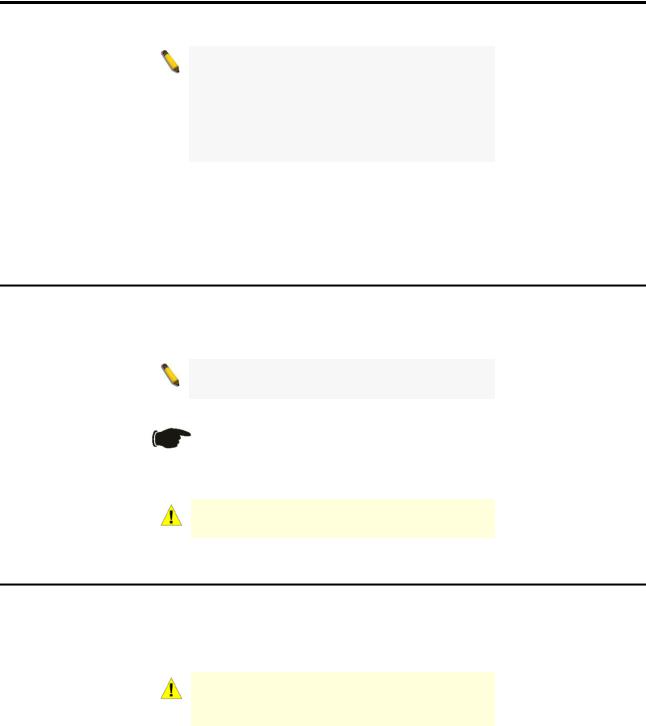
DGS-1210-16
16-Port 10/100/1000Mbps plus 4 SFP Slot Web Smart Switch.
Front Panel
Figure 1.3 – DGS-1210-16 Front Panel |
Power LED : The Power LED lights up when the Switch is connected to a power source.
Port Link/Act/Speed LED (1-20): The Link/Act/Speed LED flashes, which indicates a network link through the corresponding port. Blinking indicates that the Switch is either sending or receiving data to the port. When a port has an amber light, this indicates that the port is running on 10M or 100M. When it has a green light it is running on 1000M.
CAUTION: The Mini-GBIC ports should use UL recognized Optical
Transceiver product, Rated Laser Class I. 3.3Vdc.
Reset: By pressing the Reset button for 5 seconds, the Switch will change back to the default configuration and all changes will be lost.
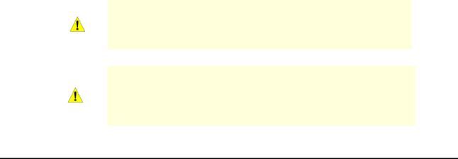
Rear Panel
SWITCH GND
AC LINE
100-240 VAC
50-60 Hz Power Cord Clip
0.5A MAX
Figure 1.4 – DGS-1210-16 Rear Panel
Power: The power port is where to connect the AC power cord.
Security Lock: Provide a Kensington-compatible security lock to be able to connect to a secure immovable device. Insert the lock into the notch and turn the key to secure the lock. The lock-and-cable apparatus should be purchased separately.
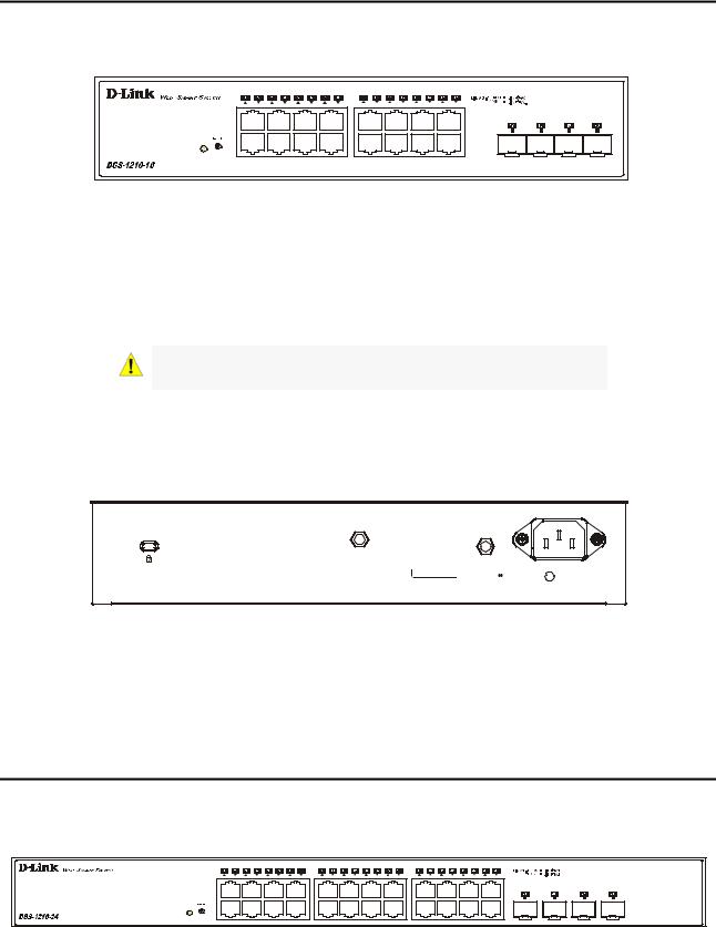
DGS-1210-24
24-Port 10/100/1000Mbps plus 4 SFP Slot Web Smart Switch.
Front Panel
Figure 1.5 – DGS-1210-24 Front Panel
Power LED : The Power LED lights up when the Switch is connected to a power source.
6
Product Introduction |
D-Link Web Smart Switch User Manual |
Port Link/Act/Speed LED (1-28): The Link/Act/Speed LED flashes, which indicates a network link through the corresponding port. Blinking indicates that the Switch is either sending or receiving data to the port. When a port has an amber light, this indicates that the port is running on 10M or 100M. When it has a green light it is running on 1000M.
Reset: Press the Reset button for 5 seconds to reset the Switch back to the default settings. All previous changes will be lost.
CAUTION: The MiniGBIC ports should use UL recognized Optical
Transceiver product, Rated Laser Class I. 3.3Vdc.
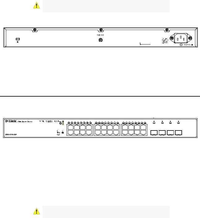
Rear Panel
Figure 1.6 DGS-1210-24 Rear Panel
Power: Connect the supplied AC power cable to this port.
Security Lock: Provide a Kensington-compatible security lock to be able to connect to a secure immovable device. Insert the lock into the notch and turn the key to secure the lock. The lock-and-cable apparatus should be purchased separately.
DGS-1210-24P
24-Port 10/100/1000Mbps PoE plus 4 SFP Slot Web Smart Switch.
Front Panel
Figure 1.7 – DGS-1210-24P Front Panel
Power LED : The Power LED lights up when the Switch is connected to a power source.
Port Link/Act/Speed LED (1-28): The Link/Act/Speed LED flashes, which indicates a network link through the corresponding port. Blinking indicates that the Switch is either sending or receiving data to the port. When a port has an amber light, this indicates that the port is running on 10M or 100M. When it has a green light it is running on 1000M.
PoE LED: The PoE LED illuminates green when power is supplied to PoE devices plugged into the ports. It illuminates amber when an error condition is met and will be off when no power is supplied.
Reset: Press the Reset button for 5 seconds to reset the Switch back to the default settings. All previous changes will be lost.
CAUTION: The MiniGBIC ports should use UL recognized Optical
Transceiver product, Rated Laser Class I. 3.3Vdc.
7
Product Introduction |
D-Link Web Smart Switch User Manual |
Rear Panel
Figure 1.8 DGS-1210-24P Rear Panel
Power: Connect the supplied AC power cable to this port.
Security Lock: Provide a Kensington-compatible security lock to be able to connect to a secure immovable device. Insert the lock into the notch and turn the key to secure the lock. The lock-and-cable apparatus should be purchased separately.
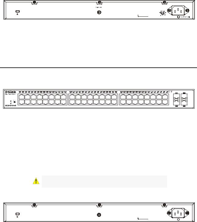
DGS-1210-48
44-Port 10/100/1000Mbps plus 4-Port Combo Copper/SFP Web Smart Switch.
Front Panel
Figure 1.9 – DGS-1210-48 Front Panel |
Power LED : The Power LED lights up when the Switch is connected to a power source.
Port Link/Act/Speed LED (1-48): The Link/Act/Speed LED flashes, which indicates a network link through the corresponding port. Blinking indicates that the Switch is either sending or receiving data to the port. When a port has an amber light, this indicates that the port is running on 10M or 100M. When it has a green light it is running on 1000M.
Fan: The Fan LED lights green when the fan work well, and lights red when the fan fail.
Reset: Press the Reset button for 5 seconds to reset the Switch back to the default settings. All previous changes will be lost.
CAUTION: The MiniGBIC ports should use UL recognized Optical
Transceiver product, Rated Laser Class I. 3.3Vdc.
Rear Panel
SWITCH GND |
|
AC LINE |
|
100-240 VAC |
|
50-60 Hz |
|
2A MAX |
Power Cord Clip |
Figure 1.10 – DGS-1210-48 Rear Panel |
|
Power: Connect the supplied AC power cable to this port.
Security Lock: Provide a Kensington-compatible security lock to be able to connect to a secure immovable device. Insert the lock into the notch and turn the key to secure the lock. The lock-and-cable apparatus should be purchased separately.
8
Hardware Installation |
D-Link Web Smart Switch User Manual |
2 Hardware Installation
This chapter provides unpacking and installation information for the D-Link Web-Smart Switch.
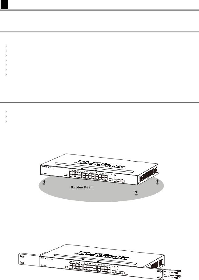
Step 1: Unpacking
Open the shipping carton and carefully unpack its contents. Please consult the packing list located in the User Manual to make sure all items are present and undamaged.
One D-Link Web-Smart Switch
One AC power cord
One set of Power Cord Clip
Four rubber feet
Screws and two mounting brackets
One Multi-lingual Getting Started Guide
One CD with Web UI Reference Guide, Getting Started Guide, D-Link Network Assistant User Guide, Language Pack Files, and D-View Module.
If any item is found missing or damaged, please contact the local reseller for replacement.
Step 2: Switch Installation
For safe switch installation and operation, it is recommended that you:
Visually inspect the power cord to see that it is secured fully to the AC power connector. Make sure that there is proper heat dissipation and adequate ventilation around the switch. Do not place heavy objects on the switch.
Desktop or Shelf Installation
When installing the switch on a desktop or shelf, the rubber feet included with the device must be attached on the bottom at each corner of the device’s base. Allow enough ventilation space between the device and the objects around it.
Figure 2.1 – Attach the adhesive rubber pads to the bottom
Rack Installation
The switch can be mounted in an EIA standard size 19-inch rack, which can be placed in a wiring closet with other equipment. To install, attach the mounting brackets to the switch’s side panels (one on each side) and secure them with the screws provided (please note that these brackets are not designed for palm size switches).
Figure 2.2 – Attach the mounting brackets to the Switch
9
Hardware Installation |
D-Link Web Smart Switch User Manual |
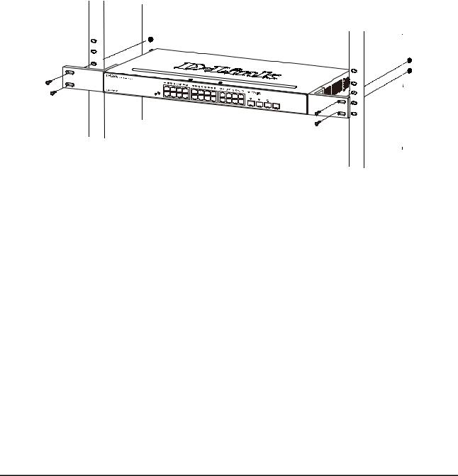
Then, use the screws provided with the equipment rack to mount the switch in the rack.
Figure 2.3 – Mount the Switch in the rack or chassis
Please be aware of following safety Instructions when installing:
A)Elevated Operating Ambient - If installed in a closed or multi-unit rack assembly, the operating ambient temperature of the rack environment may be greater than room ambient. Therefore, consideration should be given to installing the equipment in an environment compatible with the maximum ambient temperature (Tma) specified by the manufacturer.
B)Reduced Air Flow - Installation of the equipment in a rack should be such that the amount of air flow required for safe operation of the equipment is not compromised.
C)Mechanical Loading - Mounting of the equipment in the rack should be such that a hazardous condition is not achieved due to uneven mechanical loading.
D)Circuit Overloading - Consideration should be given to the connection of the equipment to the supply circuit, and the effect that overloading of the circuits might have on overcurrent protection and supply wiring. Appropriate consideration of equipment nameplate ratings should be used when addressing this concern.
E)Reliable Earthing - Reliable earthing of rack-mounted equipment should be maintained. Particular attention should be given to supply connections other than direct connections to the branch circuit (e.g. use of power strips)."
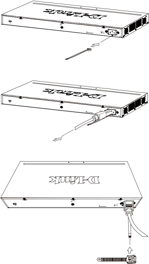
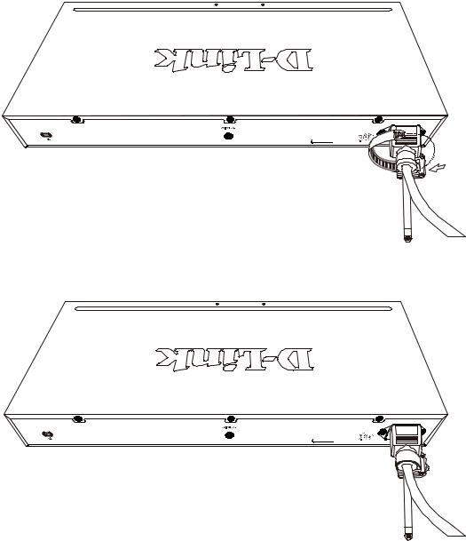
Step 3: Plugging in the AC Power Cord with Power Cord Clip
To prevent accidental removal of the AC power cord, it is recommended to install the power cord clip together with the power cord.
A) With the rough side facing down, insert the Tie Wrap into the hole below the power socket.
10
Hardware Installation |
|
D-Link Web Smart Switch User Manual |
||||
|
|
|
|
|
|
|
|
|
|
|
|
|
|
Figure 2.4 – Insert Tie Wrap to the Switch
B) Plug the AC power cord into the power socket of the Switch.
Figure 2.5 – Connect the power cord to the Switch
C) Slide the Retainer through the Tie Wrap until the end of the cord.
Figure 2.6 – Slide the Retainer through the Tie Wrap
11
Hardware Installation |
D-Link Web Smart Switch User Manual |
D) Circle the tie of the Retainer around the power cord and into the locker of the Retainer.
Figure 2.7 – Circle around the power cord
E) Fasten the tie of the Retainer until the power cord is secured.
Figure 2.8 – Secure the power cord
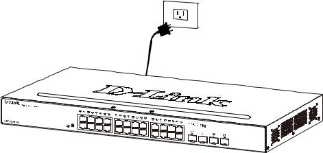
F) Users may now connect the AC power cord to an electrical outlet (preferably one that is grounded and surge protected).
12
Hardware Installation |
D-Link Web Smart Switch User Manual |
Figure 2.9 – Plugging the switch into an outlet
Power Failure
As a precaution, the switch should be unplugged in case of power failure. When power is resumed, plug the switch back in.
13
Getting Started |
D-Link Web Smart Switch User Manual |
3 Getting Started
This chapter introduces the management interface of D-Link Web-Smart Switch.
Management Options
The D-Link Web Smart Switch can be managed through any port on the device by using the Web-based Management.
Each switch must be assigned its own IP Address, which is used for communication with the Web-Based Management or a SNMP network manager. The PC should have an IP address in the same range as the switch. Each switch can allow up to four users to access the Web-Based Management concurrently.
Please refer to the following installation instructions for the Web-based Management and the D-Link Network Assistant (DNA).
Using Web-based Management
After a successful physical installation, you can configure the Switch, monitor the network status, and display statistics using a web browser.
Supported Web Browsers
The embedded Web-based Management currently supports the following web browsers:
Internet Explorer 6 or later version
Firefox 3.0 or later version
Chrome 5.0 or later version
Safari 4.0 or later version Opera 10 or later version
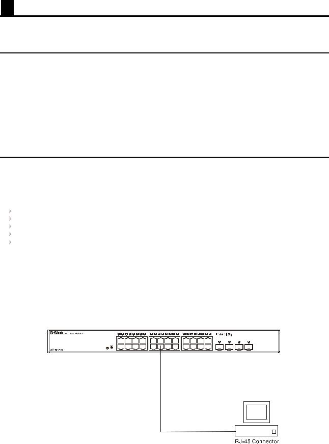
Connecting to the Switch
You will need the following equipment to begin the web configuration of your device:
1.A PC with a RJ-45 Ethernet connection
2.A standard Ethernet cable
Connect the Ethernet cable to any of the ports on the front panel of the switch and to the Ethernet port on the PC.
Figure 3.1 – Connected Ethernet cable
14
Getting Started |
D-Link Web Smart Switch User Manual |
Login Web-based Management
In order to login and configure the switch via an Ethernet connection, the PC must have an IP address in the same subnet as the switch. For example, if the switch has an IP address of 10.90.90.90, the PC should have an IP address of 10.x.y.z (where x/y is a number between 0 ~ 254 and z is a number between 1 ~ 254), and a subnet mask of 255.0.0.0. Open the web browser and enter 10.90.90.90 (the factory-default IP address) in the address bar. Then press <Enter>.
Figure 3.2 – Enter the IP address 10.90.90.90 in the web browser
NOTE: The switch's factory default IP address is 10.90.90.90 with a subnet mask of 255.0.0.0 and a default gateway of 0.0.0.0.
When the following logon dialog box appears, enter the password and choose the language of the Webbased Management interface then click OK.
The switch supports 10 languages including English, Traditional Chinese, Simplified Chinese, German, Spanish, French, Italian, Portuguese, Japanese and Russian. By default, the password is admin and the language is English. For more information about language packs, refer to Language Management.
Figure 3.3 – Logon Dialog Box
Smart Wizard
After a successful login, the Smart Wizard will guide you through essential settings of the D-Link Web Smart Switch. Please refer to the Smart Wizard Configuration section for details.
Web-based Management
By clicking the Exit button in the Smart Wizard, you will enter the Web-based Management interface. Please refer to Chapter 5 Configuration for detailed instructions.
D-Link Network Assistant (DNA)
The D-Link Network Assistant (DNA), included in the installation CD, is a program that allows administrators to quickly discover all D-Link smart switches and D-Link Discover Protocol (DDP) supported devices (for a list of supported models, refer to the D-Link Network Assistant (DNA) User Guide), that are in the same subnet as the PC, collect traps and log messages, and provide quick access to basic configurations of the switch. This tool is only for computers running Windows 7, Vista, XP, or 2000 on both 32/64bit systems. There are two options for the installation of the DNA; one is through the Autorun program on the installation CD and the other is manual installation.
15

Getting Started |
D-Link Web Smart Switch User Manual |
NOTE: Please be sure to uninstall any existing
DNA from your PC before installing the latest
DNA.
For detailed explanations of the DNA functions, please refer to D-Link Network Assistant (DNA) User Guide.
16
Configuration |
D-Link Web Smart Switch User Manual |
4 Configuration
The features and functions of the D-Link Web Smart Switch can be configured for optimum use through the Web-based Management Utility.
Smart Wizard Configuration
After a successful login, the Smart Wizard will guide you through essential settings of the D-Link Web Smart Switch. If you do not plan to change anything, click Exit to leave the Wizard and enter the Web Interface. You can also skip it by clicking Ignore the wizard next time for the next time you logon to the Web-based Management.
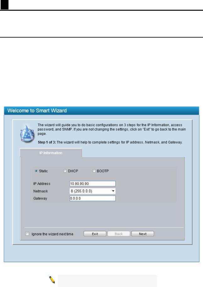
IP Information
IP Information will guide you to do basic configurations in 3 steps for the IP Information, access password, and SNMP.
Select Static, DHCP or BOOTP, and enter the desired new IP Address, select the Netmask and enter the Gateway address, then click the Next button to enter the next Password setting page. (No need to enter IP Address, Netmask and Gateway if DHCP and BOOTP are selected.) The Smart Wizard is for the quick setting in IPv4 environment. If you are not changing the settings, click the Exit button to go to the main page of Webbased Management. You can also tick Ignore the wizard next time check box to skip wizard setting when the switch
boots up.
Figure 4.1 – IP Information in Smart Wizard
NOTE: The Smart Wizard supports quick settings for IPv4 network.
17
Configuration |
D-Link Web Smart Switch User Manual |
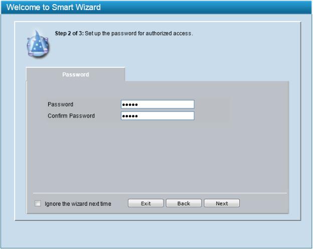
Password
Type the desired new password in the Password field and again in the Confirm Password field, then click the Next button to the SNMP setting page.
Figure 4.2 – Password in Smart Wizard
18
Configuration |
D-Link Web Smart Switch User Manual |
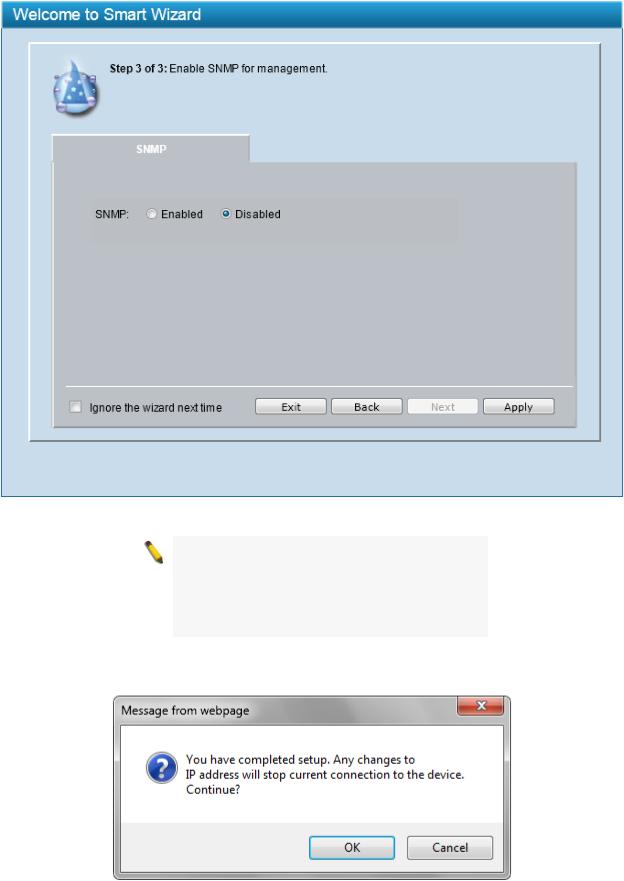
SNMP
The SNMP Setting allows you to quickly enable or disable the SNMP function. The default SNMP Setting is Disabled. Click Enabled and then click Apply to make it effective.
Figure 4.3 – SNMP in Smart Wizard
NOTE: Changing the system IP address will disconnect you from the current connection. Please enter the correct IP address in the Web browser again and make sure your PC is in the same subnet with the switch. See Login Webbased Management for a detailed description.
When IP Address in Step 1 is changed, the following dialog box appears. Click OK to confirm all settings in the Wizard, and start a new web browser.
Figure 4.4 – Confirm the changes of IP address in Smart Wizard
19
Configuration |
D-Link Web Smart Switch User Manual |
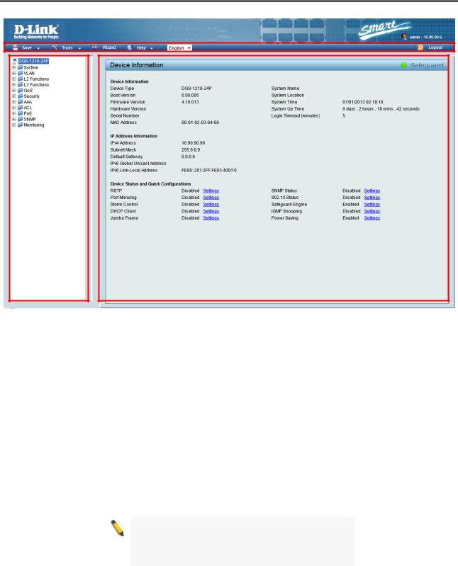
Web-based Management
After clicking the Exit button in Smart Wizard, you will see the screen below:
Tool Bar
Function Tree
Main Configuration Screen
Figure 4.5 – Web-based Management
The above image is the Web-based Management screen. The three main areas are the Tool Bar on top, the
Function Tree, and the Main Configuration Screen.
The Tool Bar provides a quick and convenient way for essential utility functions like firmware and configuration management.
By choosing different functions in the Function Tree, you can change all the settings in the Main Configuration Screen. The main configuration screen will show the current status of your Switch by clicking the model name on top of the function tree.
At the upper right corner of the screen the username and current IP address will be displayed.
Under the username is the Logout button. Click this to end this session.
NOTE: If you close the web browser without clicking the Logout button first, then it will be seen as an abnormal exit and the login session will still be occupied.
Finally, by clicking on the D-Link logo at the upper-left corner of the screen you will be redirected to the local D-Link website.
20
Configuration |
D-Link Web Smart Switch User Manual |
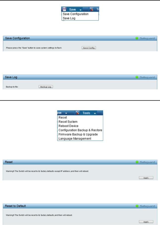
Tool Bar > Save Menu
The Save Menu provides Save Configuration and Save Log functions.
Figure 4.6 – Save Menu
Save Configuration
Select to save the entire configuration changes you have made to the device to switch’s non-volatile RAM.
Figure 4.7 – Save Configuration
Save Log
Save the log entries to your local drive and a pop-up message will prompt you for the file path. You can view or edit the log file by using text editor (e.g. Notepad).
Figure 4.8 – Save Log
Tool Bar > Tools Menu
The Tools Menu offers global function controls Reset, Reset System, Reboot Device, Configuration Backup & Restore, Firmware Backup & Upgrade, and Language Management.
Figure 4.9 – Tools Menu
Reset
Provide a safe reset option for the Switch. All configuration settings in non-volatile RAM will be reset to factory default except for the IP address.
Figure 4.10 – Tools Menu > Reset
Reset System
Provide another safe reset option for the Switch. All configuration settings in non-volatile RAM will reset to factory default and the Switch will reboot.
Figure 4.11 – Tools Menu > Reset System
21
Configuration |
D-Link Web Smart Switch User Manual |
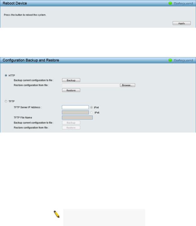
Reboot Device
Provide a safe way to reboot the system. Click Apply to restart the Switch.
Figure 4.12 – Tools Menu > Reboot Device
Configuration Backup and Restore
Allow the current configuration settings to be saved to a file (not including the password), and if necessary, you can restore the configuration settings from this file. Two methods can be selected: HTTP or TFTP.
Figure 4.13 – Tools Menu > Configure Backup and Restore
HTTP: Backup or restore the configuration file to or from your local drive.
Click Backup to save the current settings to your disk.
Click Browse to browse your inventories for a saved backup settings file.
Click Restore after selecting the backup settings file you want to restore.
TFTP: TFTP (Trivial File Transfer Protocol) is a file transfer protocol that allows you to transfer files to a remote TFTP server. Specify TFTP Server IP Address with IPv4 or IPv6 address and TFTP File Name for the configuration file you want to save to or restore from.
Click Backup to save the current settings to the TFTP server.
Click Restore after selecting the backup settings file you want to restore.
NOTE: The Switch will reboot after restore, and all current configurations will be lost
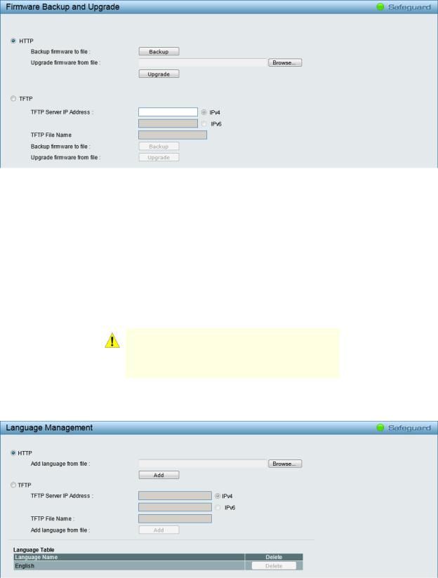
Firmware Backup and Upgrade
Allow for the firmware to be saved, or for an existing firmware file to be uploaded to the Switch. Two methods can be selected: HTTP or TFTP.
22
Configuration |
D-Link Web Smart Switch User Manual |
Figure 4.14 – Tools Menu > Firmware Backup and Upgrade
HTTP: Backup or upgrade the firmware to or from your local PC drive.
Click Backup to save the firmware to your disk.
Click Browse to browse your inventories for a saved firmware file.
Click Upgrade after selecting the firmware file you want to restore.
TFTP: Backup or upgrade the firmware to or from a remote TFTP server. Specify TFTP Server IP Address with IPv4 or IPv6 address and TFTP File Name for the firmware file you want to save to or restore from.
Click Backup to save the firmware to the TFTP server.
Click Upgrade after selecting the firmware file you want to restore.
CAUTION: Do not disconnect the PC or remove the power cord from the Switch until the upgrade completes. The Switch may crash if the firmware upgrade is incomplete.
Language Management
Allow to select different language packages for the Switch. Two methods can be selected: HTTP or TFTP.
Figure 4.15 – Tools Menu > Language Management
HTTP: Install the language pack from your local PC drive.
Click Browse to find the file in your PC.
Click Add after selecting the language pack you want to install.
23
Configuration |
D-Link Web Smart Switch User Manual |
TFTP: Install the language pack from a remote TFTP server. Specify TFTP Server IP Address with IPv4 or IPv6 address and TFTP File Name for the language file you want to install.
Click Add after selecting the language pack file you want to install.
NOTE: Language pack files are included on the
CD in the Language Package folder.
Tool Bar > Smart Wizard
By clicking the Smart Wizard button, you can return to the Smart Wizard if you wish to make any changes there.
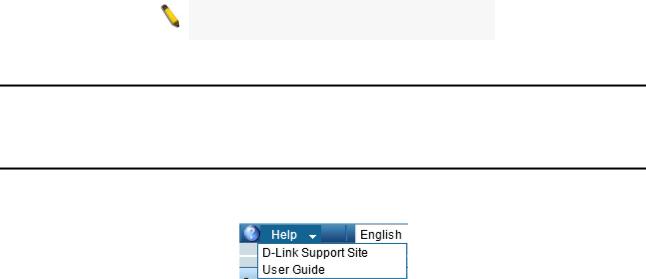
Tool Bar > Online Help
The Online Help provides two ways of online support: D-Link Support Site will lead you to the D-Link website where you can find online resources such as updated firmware images; User Guide can offer an immediate reference for the feature definition or configuration guide.
Figure 4.16 – Online Help
24
Loading...