


D-Link™ DGS-1008D
8-Port 10/100/1000Mbps Gigabit Ethernet Switch
Manual
Rev. 2.01
Building Networks for People
RECYCLABLE

D-Link DGS-1008D Unmanaged Gigabit Ethernet Switch
____________________
Information in this document is subject to change without notice. © 2003 D-Link Computer Corporation. All rights reserved.
Reproduction in any manner whatsoever without the written permission of D-Link Computer Corporation is strictly forbidden.
Trademarks used in this text: D-Link and the D-LINK logo are trademarks of D-Link Computer Corporation; Microsoft and Windows are registered trademarks of Microsoft Corporation.
Other trademarks and trade names may be used in this document to refer to either the entities claiming the marks and names or their products. D-Link Computer Corporation disclaims any proprietary interest in trademarks and trade names other than its own.
October 2003 P/N DGS1008D..B1
FCC Warning
This equipment has been tested and found to comply with the limits for a Class B digital device, pursuant to Part 15 of the FCC Rules. These limits are designed to provide reasonable protection against harmful interference when the equipment is operated in a commercial environment. This equipment generates, uses, and can radiate radio frequency energy and, if not installed and used in accordance with this user’s guide, may cause harmful interference to radio communications. Operation of this equipment in a residential area is likely to cause harmful interference in which case the user will be required to correct the interference at his own expense.
CE Mark Warning
This is a Class B product. In a domestic environment, this product may cause radio interference in which case the user may be required to take adequate measures.
Warnung!
Dies ist ein Produkt der Klasse B. Im Wohnbereich kann dieses Produkt Funkstoerungen verursachen. In diesem Fall kann vom Benutzer verlangt werden, angemessene Massnahmen zu ergreifen.
Precaución!
Este es un producto de Clase B. En un entorno doméstico, puede causar interferencias de radio, en cuyo case, puede requerirse al usuario para que adopte las medidas adecuadas.
Attention!
Ceci est un produit de classe B. Dans un environnement domestique, ce produit pourrait causer des interférences radio, auquel cas l`utilisateur devrait prendre les mesures adéquates.
Attenzione!
Il presente prodotto appartiene alla classe B. Se utilizzato in ambiente domestico il prodotto può causare interferenze radio, nel cui caso è possibile che l`utente debba assumere provvedimenti adeguati.
VCCI Warning
BSMI Warning

D-Link DGS-1008D Unmanaged Gigabit Ethernet Switch
|
CONTENTS |
INTRODUCTION.................................................................................................................................................. |
1 |
ETHERNET TECHNOLOGY...................................................................................................................................... |
1 |
Fast Ethernet Technology ................................................................................................................................ |
1 |
Gigabit Ethernet Technology ........................................................................................................................... |
1 |
SWITCHING TECHNOLOGY .................................................................................................................................... |
1 |
SWITCH DESCRIPTION ........................................................................................................................................... |
2 |
Features ........................................................................................................................................................... |
2 |
FRONT-PANEL COMPONENTS................................................................................................................................ |
3 |
LED Indicators................................................................................................................................................. |
3 |
REAR PANEL DESCRIPTION ................................................................................................................................... |
5 |
INSTALLATION ................................................................................................................................................... |
6 |
Package Contents............................................................................................................................................. |
6 |
BEFORE YOU CONNECT TO THE NETWORK ........................................................................................................... |
6 |
MOUNTING THE SWITCH ON A WALL .................................................................................................................... |
7 |
ATTACHING THE RUBBER FEET............................................................................................................................. |
7 |
PROVIDE FOR ADEQUATE VENTILATION ............................................................................................................... |
8 |
POWER ON ............................................................................................................................................................ |
8 |
Power Failure .................................................................................................................................................. |
8 |
CONNECTING THE SWITCH ........................................................................................................................... |
9 |
SWITCH TO END NODE ......................................................................................................................................... |
9 |
SWITCH TO HUB OR SWITCH ............................................................................................................................... |
10 |
CONNECTING TO NETWORK BACKBONE OR SERVER .......................................................................................... |
10 |
TECHNICAL SPECIFICATIONS..................................................................................................................... |
11 |
GLOSSARY.......................................................................................................................................................... |
12 |
WARRANTY AND REGISTRATION INFORMATION................................................................................ |
18 |
(ALL COUNTRIES AND REGIONS EXCLUDING USA) ............................................................................................. |
18 |
D-Link DGS-1008D Unmanaged Gigabit Ethernet Switch
Preface
The DGS-1008D User’s Guide is divided into sections that describe the system installation and operating instructions with examples.
Section 1, Introduction - A description of the physical features of the switch, including LED indicators, ports and panel descriptions.
Section 2, Installation – A description of the physical installation of the switch including connecting the switch to the network and connecting stacked switch groups.
Section 3, Connecting the Switch – A description of how to connect your switch to an end node, hub, switch or backbone server.
Appendix A, Technical Specifications - The technical specifications of the DGS-1008D. Glossary – Lists definitions for terms and acronyms used in this document.
Index – Index of relevant terms in the DGS-1008D User’s Guide.
Intended Readers
The DGS-1008D User’s Guide contains information for setup and management and of the DGS-1008D switch. This guide is intended for network managers familiar with network management concepts and terminology.
Notes, Notices, and Cautions
NOTE: A NOTE indicates important information that helps you make better use of your device.
NOTICE: A NOTICE indicates either potential damage to hardware or loss of data and tells you how to avoid the problem.
CAUTION: A CAUTION indicates a potential for property damage, personal injury, or death.
iv

D-Link DGS-1008D Unmanaged Gigabit Ethernet Switch
Safety Instructions
Use the following safety guidelines to ensure your own personal safety and to help protect your system from potential damage. Throughout this safety section, the caution icon ( ) is used to indicate cautions and precautions that you need to review and follow.
Safety Cautions
To reduce the risk of bodily injury, electrical shock, fire, and damage to the equipment, observe the following precautions.
Observe and follow service markings. Do not service any product except as explained in your system documentation. Opening or removing covers that are marked with the triangular symbol with a lightning bolt may expose you to electrical shock. Only a trained service technician should service components inside these compartments.
If any of the following conditions occur, unplug the product from the electrical outlet and replace the part or contact your trained service provider:
–The power cable, extension cable, or plug is damaged.
–An object has fallen into the product.
–The product has been exposed to water.
–The product has been dropped or damaged.
–The product does not operate correctly when you follow the operating instructions.
•Keep your system away from radiators and heat sources. Also, do not block cooling vents.
•Do not spill food or liquids on your system components, and never operate the product in a wet environment. If the system gets wet, see the appropriate section in your troubleshooting guide or contact your trained service provider.
•Do not push any objects into the openings of your system. Doing so can cause fire or electric shock by shorting out interior components.
•Use the product only with approved equipment.
•Allow the product to cool before removing covers or touching internal components.
•Operate the product only from the type of external power source indicated on the electrical ratings label. If you are not sure of the type of power source required, consult your service provider or local power company.
•To help avoid damaging your system, be sure the voltage selection switch (if provided) on the power supply is set to match the power available at your location:
–115 volts (V)/60 hertz (Hz) in most of North and South America and some Far Eastern countries such as South Korea and Taiwan
–100 V/50 Hz in eastern Japan and 100 V/60 Hz in western Japan
–230 V/50 Hz in most of Europe, the Middle East, and the Far East
•Also be sure that attached devices are electrically rated to operate with the power available in your location.
v
D-Link DGS-1008D Unmanaged Gigabit Ethernet Switch
Safety Instructions (continued)
•Use only approved power cable(s). If you have not been provided with a power cable for your system or for any AC-powered option intended for your system, purchase a power cable that is approved for use in your country. The power cable must be rated for the product and for the voltage and current marked on the product's electrical ratings label. The voltage and current rating of the cable should be greater than the ratings marked on the product.
•To help prevent electric shock, plug the system and peripheral power cables into properly grounded electrical outlets. These cables are equipped with three-prong plugs to help ensure proper grounding. Do not use adapter plugs or remove the grounding prong from a cable. If you must use an extension cable, use a 3-wire cable with properly grounded plugs.
•Observe extension cable and power strip ratings. Make sure that the total ampere rating of all products plugged into the extension cable or power strip does not exceed 80 percent of the ampere ratings limit for the extension cable or power strip.
•To help protect your system from sudden, transient increases and decreases in electrical power, use a surge suppressor, line conditioner, or uninterruptible power supply (UPS).
•Position system cables and power cables carefully; route cables so that they cannot be stepped on or tripped over. Be sure that nothing rests on any cables.
•Do not modify power cables or plugs. Consult a licensed electrician or your power company for site modifications. Always follow your local/national wiring rules.
•When connecting or disconnecting power to hot-pluggable power supplies, if offered with your system, observe the following guidelines:
–Install the power supply before connecting the power cable to the power supply.
–Unplug the power cable before removing the power supply.
–If the system has multiple sources of power, disconnect power from the system by
unplugging all power cables from the power supplies.
•Move products with care; ensure that all casters and/or stabilizers are firmly connected to the system. Avoid sudden stops and uneven surfaces.
General Precautions for Rack-Mountable Products
Observe the following precautions for rack stability and safety. Also refer to the rack installation documentation accompanying the system and the rack for specific caution statements and procedures.
Systems are considered to be components in a rack. Thus, "component" refers to any system as well as to various peripherals or supporting hardware.
CAUTION: Installing systems in a rack without the front and side stabilizers installed could cause the rack to tip over, potentially resulting in bodily injury under certain circumstances. Therefore, always install the stabilizers before installing components in the rack.
After installing system/components in a rack, never pull more than one component out of the rack on its slide assemblies at one time. The weight of more than one extended component could cause the rack to tip over and may result in serious injury.
•Before working on the rack, make sure that the stabilizers are secured to the rack, extended to the floor, and that the full weight of the rack rests on the floor. Install front and side stabilizers on a single rack or front stabilizers for joined multiple racks before working on the rack.
vi
D-Link DGS-1008D Unmanaged Gigabit Ethernet Switch
Safety Instructions (continued)
Always load the rack from the bottom up, and load the heaviest item in the rack first. Make sure that the rack is level and stable before extending a component from the rack.
Use caution when pressing the component rail release latches and sliding a component into or out of a rack; the slide rails can pinch your fingers.
After a component is inserted into the rack, carefully extend the rail into a locking position, and then slide the component into the rack.
Do not overload the AC supply branch circuit that provides power to the rack. The total rack load should not exceed 80 percent of the branch circuit rating.
Ensure that proper airflow is provided to components in the rack.
Do not step on or stand on any component when servicing other components in a rack.
NOTE: A qualified electrician must perform all connections to DC power and to safety grounds. All electrical wiring must comply with applicable local or national codes and practices.
CAUTION: Never defeat the ground conductor or operate the equipment in the absence of a suitably installed ground conductor. Contact the appropriate electrical inspection authority or an electrician if you are uncertain that suitable grounding is available.
CAUTION: The system chassis must be positively grounded to the rack cabinet frame. Do not attempt to connect power to the system until grounding cables are connected. Completed power and safety ground wiring must be inspected by a qualified electrical inspector. An energy hazard will exist if the safety ground cable is omitted or disconnected.
Protecting Against Electrostatic Discharge
Static electricity can harm delicate components inside your system. To prevent static damage, discharge static electricity from your body before you touch any of the electronic components, such as the microprocessor. You can do so by periodically touching an unpainted metal surface on the chassis.
You can also take the following steps to prevent damage from electrostatic discharge (ESD):
1.When unpacking a static-sensitive component from its shipping carton, do not remove the component from the antistatic packing material until you are ready to install the component in your system. Just before unwrapping the antistatic packaging, be sure to discharge static electricity from your body.
2.When transporting a sensitive component, first place it in an antistatic container or packaging.
3.Handle all sensitive components in a static-safe area. If possible, use antistatic floor pads and workbench pads and an antistatic grounding strap.
vii

D-Link DGS-1008D Unmanaged Gigabit Ethernet Switch
SECTION 1
Introduction
Ethernet Technology
Switch Description
Features
Ports
Front-Panel Components
Ethernet Technology
Fast Ethernet Technology
The growing importance of LANs and the increasing complexity of desktop computing applications are fueling the need for high performance networks. A number of high-speed LAN technologies are proposed to provide greater bandwidth and improve client/server response times. Among them, Fast Ethernet, or 100BASE-T, provides a non-disruptive, smooth evolution from 10BASE-T technology.
100Mbps Fast Ethernet is a standard specified by the IEEE 802.3 LAN committee. It is an extension of the 10Mbps Ethernet standard with the ability to transmit and receive data at 100Mbps, while maintaining the Carrier Sense Multiple Access with Collision Detection (CSMA/CD) Ethernet protocol.
Gigabit Ethernet Technology
Gigabit Ethernet is an extension of IEEE 802.3 Ethernet utilizing the same packet structure, format, and support for CSMA/CD protocol, full duplex, flow control, and management objects, but with a tenfold increase in theoretical throughput over 100Mbps Fast Ethernet and a one hundred-fold increase over 10Mbps Ethernet. Since it is compatible with all 10Mbps and 100Mbps Ethernet environments, Gigabit Ethernet provides a straightforward upgrade without wasting a company’s existing investment in hardware, software, and trained personnel.
The increased speed and extra bandwidth offered by Gigabit Ethernet is essential to coping with the network bottlenecks that frequently develop as computers and their busses get faster and more users use applications that generate more traffic. Upgrading key components, such as your backbone and servers to Gigabit Ethernet can greatly improve network response times as well as significantly speed up the traffic between your subnetworks.
Gigabit Ethernet enables fast optical fiber connections to support video conferencing, complex imaging, and similar data-intensive applications. Likewise, since data transfers occur 10 times faster than Fast Ethernet, servers outfitted with Gigabit Ethernet NIC’s are able to perform 10 times the number of operations in the same amount of time.
In addition, the phenomenal bandwidth delivered by Gigabit Ethernet is the most cost-effective method to take advantage of today and tomorrow’s rapidly improving switching and routing internetworking technologies.
Switching Technology
Another key development pushing the limits of Ethernet technology is in the field of switching technology. A switch bridges Ethernet packets at the MAC address level of the Ethernet protocol transmitting among connected Ethernet or fast Ethernet LAN segments.
Switching is a cost-effective way of increasing the total network capacity available to users on a local area network. A switch increases capacity and decreases network loading by making it possible for a local area network to be divided into different segments which don’t compete with each other for network transmission capacity, giving a decreased load on each.
The switch acts as a high-speed selective bridge between the individual segments. Traffic that needs to go from one segment to another (from one port to another) is automatically forwarded by the switch, without interfering
1

D-Link DGS-1008D Unmanaged Gigabit Ethernet Switch
with any other segments (ports). This allows the total network capacity to be multiplied, while still maintaining the same network cabling and adapter cards.
For Fast Ethernet or Gigabit Ethernet networks, a switch is an effective way of eliminating problems of chaining hubs beyond the “two-repeater limit.” A switch can be used to split parts of the network into different collision domains, for example, making it possible to expand your Fast Ethernet network beyond the 205-meter network diameter limit for 100BASE-TX networks. Switches supporting both traditional 10Mbps Ethernet and 100Mbps Fast Ethernet are also ideal for bridging between existing 10Mbps networks and new 100Mbps networks.
Switching LAN technology is a marked improvement over the previous generation of network bridges, which were characterized by higher latencies. Routers have also been used to segment local area networks, but the cost of a router and the setup and maintenance required make routers relatively impractical. Today’s switches are an ideal solution to most kinds of local area network congestion problems.
Switch Description
The DGS-1008D Switch module is equipped with eight ports providing dedicated 10, 100 or 1000 Mbps bandwidth. These ports can be used for connecting PCs, servers, and hubs. The eight multi-speed ports use standard twisted pair cabling and are ideal for segmenting networks into small, connected subnets. Each port can support up to 2000 Mbps of throughput in full-duplex mode. This stand-alone Switch enables the network to use some of the most demanding multimedia and imaging applications concurrently with other user applications without creating bottlenecks.
Features
The DGS-1008D 8-Port 1000BASE-T Gigabit Ethernet Switch was designed for easy installation and high performance in an environment where traffic on the network and the number of users increase continuously.
•Eight (8) 1000BASE-T Gigabit Ethernet ports
•Cable Diagnostic function at Switch boot
•Supports Auto-Negotiation for 10/100/1000Mbps and duplex mode
•Supports Auto-MDIX for each port
•Support Full/Half duplex transfer mode for 10 and 100Mbps
•Support Full duplex transfer mode for 1000Mbps
•Full wire speed reception and transmission
•Store-and-Forward switching method
•Supports 4K absolute MAC addresses
•Supports 1M Bits RAM for data buffering
•Extensive front-panel diagnostic LEDs
•IEEE 802.3x flow control for full-duplex
•Back pressure flow control for half-duplex
2
D-Link DGS-1008D Unmanaged Gigabit Ethernet Switch
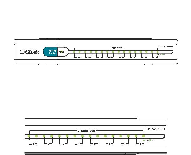
Front-Panel Components
The front panel of the Switch consists of LED indicators, 8(10/100/1000 Mbps) Ethernet ports.
Figure 1-1. Front Panel View of the switch
Comprehensive LED indicators display the status of the switch and the network.
LED Indicators
The LED indicators of the Switch include Power, 100/1000Mbps and Link/Act. The following shows the LED indicators for the Switch along with an explanation of each indicator.
Figure 1-1. LED Indicators
LED Indicators
Comprehensive LED indicators display the conditions of the Switch and status of the network. A description of these LED indicators follows (see LED Indicators). The LED indicators of the Switch include Power, Link/Act, 1000Mbps and 100Mbps.
Power Indicator
This green indicator illuminates when the Switch is receiving power.
Link / Act
This green indicator illuminates steadily when a port is connected to a station successfully and has a good link. The indicator will blink to indicate that a port is transmitting or receiving data on the network.
Speed — 100Mbps/amber; 1000Mbps/green; 10Mbps/off
This indicator is amber-colored when the port is connected to a 100Mbps Fast Ethernet station. It is green when the port is connected to a 1000Mbps Ethernet station. It is not illuminated when the port is connected to a 10Mbps Ethernet station.
Cable Diagnostic − LED Indications
When the Switch is booted, the Cable Diagnostic function is initialized and run. The Cable Diagnostic function will detect three common faults in an Ethernet cable connecting the Switch to a remote network device: an open circuit (a lack of continuity between the pins at each end of the Ethernet cable or a disconnected cable), a short circuit (two or more conductors short-circuited), and improper termination (a termination resistance greater than the specified 100 ohms). Any of these common cable faults will be detected by the Cable Diagnostic function and the LEDs will display the results of the Cable Diagnostic function as follows:
Open, Short, or Improper Termination − Speed LED: Amber − Link/Act LED: Off Cable connection good − Speed LED: Green − Link/Act LED: Off
The Cable Diagnostic function operates only during the Switch boot (when the Switch is first powered on.)
3
 Loading...