


Quick Installation Guide
Краткое руководство по установке
DGS-1010MP
10-Port Unmanaged Gigabit PoE Switch
Неуправляемый коммутатор с 9 портами 10/100/1000Base-T, 1 портом 1000Base-X SFP, функцией энергосбережения и
поддержкой QoS (8 портов с поддержкой PoE 802.3af/at (30 Вт), PoE-бюджет 125 Вт)

Before You Begin
This Quick Installation Guide gives you step-by- step instructions for setting up your DGS-1010MP 10-Port Unmanaged Gigabit PoE Switch. The model you have purchased may appear slightly different from the one shown in the illustrations. For more detailed information about the switch, please refer to the User Manual.
Package Contents
This DGS-1010MP package should include the following items:
•1 x DGS-1010MP
•1 x Power cord
•1 x Power cord retainer
•1 x Rack mount kit and rubber feet
•1 x Quick Installation Guide
If any of the above items are damaged or missing, please contact your local D-Link reseller.
Hardware Overview
LED Indicators
4
|
|
|
|
|
|
|
|
|
|
|
|
|
|
|
|
|
|
|
|
|
|
|
|
|
|
|
|
|
|
|
|
|
|
|
1 |
2 |
3 |
|
|||||
|
|
|
|
|
|
|
Figure 1 |
|||
|
|
|
|
|
|
|
|
|
||
# |
LED |
Status |
|
|
|
|
|
Description |
||
|
|
Solid |
|
|
|
The device is powered on. |
||||
1 |
Power |
green |
|
|
|
|
|
|
|
|
|
|
Off |
|
|
|
The device is powered off. |
||||
|
|
|
|
|
|
|
|
|||
|
|
|
|
|
|
|
Indicates that the total PoE power output |
|||
|
|
Solid |
|
|
|
of the switch has exceeded the Guard |
||||
|
|
amber |
|
|
|
Band threshold of 118 W, but is still below |
||||
|
|
|
|
|
|
|
the total budget of 125 W. |
|||
|
PoE Max |
|
|
|
|
|
|
|||
2 |
Blinking |
|
|
|
The total PoE budget of 125 W has been |
|||||
|
|
|
|
|
exceeded and no additional devices can |
|||||
|
|
amber |
|
|
|
|||||
|
|
|
|
|
be powered through the switch. |
|||||
|
|
|
|
|
|
|
||||
|
|
|
|
|
|
|
|
|||
|
|
Off |
|
|
|
The total PoE power consumption is below |
||||
|
|
|
|
|
the 118 W Guard Band threshold. |
|||||
|
|
|
|
|
|
|
||||
|
|
|
|
|
|
|
|
|
|
|
# |
LED |
Status |
Description |
|
|
|
Solid |
There is an active link negotiated at 10/100 |
|
|
|
amber |
Mbps on this port. |
|
|
|
|
|
|
|
Link/Act/ |
Blinking |
There is traffic on the port at 10/100 Mbps. |
|
3 |
Speed |
amber |
|
|
(Ports 1 |
Solid |
There is an active link negotiated at |
||
|
||||
|
to 10) |
green |
1000 Mbps on this port. |
|
|
|
|
|
|
|
|
Blinking |
There is traffic on the port at 1000 Mbps. |
|
|
|
green |
|
|
|
|
|
|
|
|
|
Solid |
The port is providing power to the |
|
|
|
green |
connected PoE-powered device. |
|
|
|
|
|
|
|
PoE |
|
Indicates a PoE-powered device is |
|
|
Blinking |
connected to this PoE port, but the switch |
||
4 |
(Ports |
|||
amber |
has insufficient remaining power budget |
|||
|
1 to 8) |
|||
|
|
to power the device. |
||
|
|
|
||
|
|
|
|
|
|
|
Off |
There is no PoE-powered device |
|
|
|
connected to this port. |
||
|
|
|
||
|
|
|
|
|
|
|
|
Table 1 |
Front Panel Connectors
|
|
|
|
|
|
|
|
1 |
2 |
3 |
|||
|
|
|
Figure 2 |
|
|
|
|
|
|
|
|
||
# |
Item |
Description |
|
|
||
|
Ports 1 ~ 8 |
10/100/1000 Mbps PoE-capable ports for |
||||
1 |
connecting Ethernet devices and PoE- |
|||||
|
|
|
powered devices. |
|
|
|
|
|
|
|
|||
|
Port 9 |
10/100/1000 Mbps Ethernet uplink port |
||||
2 |
for connecting to another switch using an |
|||||
|
|
|
Ethernet cable. |
|
|
|
|
|
|
|
|||
3 |
Port 10 |
100/1000 Mbps SFP uplink port for installing a |
||||
compatible SFP transceiver. |
|
|
||||
|
|
|
|
|
||
|
|
|
|
|
|
|
|
|
|
Table 2 |
|
|
|
Rear Panel Connectors
|
|
|
|
|
|
|
|
|
|
|
|
|
|
|
|
|
|
|
|
|
|
|
|
|
1 2 |
3 |
4 |
||||
|
|
|
|
Figure 3 |
|
|
|
|
|
|
|
|
|||
# |
Item |
|
|
Description |
|||
1 |
Power Input |
This is used to connect the power cable to the |
|||||
switch. |
|
|
|||||
|
|
|
|
|
|
||
2Power Cord This is used for securing the power cord Retainer Slot retainer to the switch.
3Switch GND This is used to connect the switch to ground.
4Kensington This is used to attach a Kensington security
Lock Input lock.
Table 3
ENGLISH
2
ENGLISH
Hardware Installation
Before You Begin
Observe the following precautions to help prevent shutdowns, equipment failures, and personal injury:
•Install the DGS-1010MP in a cool and dry place. Refer to the technical specifications in the user manual for the acceptable operating temperature and humidity ranges.
•Install the switch in a site free from strong electromagnetic sources, vibration, dust, and direct sunlight.
•Leave at least 10 cm of space to the left and righthand side of the switch for ventilation.
•Visually inspect the power connector and make sure that it is fully secured to the power cord.
•Do not stack any devices on top of the switch.
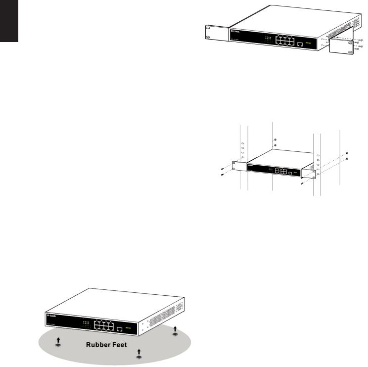
Using the Switch on a Flat Surface
The included rubber pads can be placed on the bottom of the device to prevent it from damaging the surface it is placed on.
1.Remove the rubber pads from the adhesive strip.
2.Stick one pad on each corner on the bottom panel of the switch.
Figure 4
Mounting the Switch in a Rack
The DGS-1010MP can be mounted into a standard 19” server rack.
1.Attach the included mounting brackets to the sides of the switch and secure them using the provided screws.
Figure 5
2.Install the switch into the rack.
3.Use the screws that were provided with the rack to secure the switch to the rack.
Figure 6
Grounding the Switch
This step must be completed before powering on the switch.
Required tools and equipment for grounding
•Grounding screw (included) and one M4x6 (metric) pan-head screw (not included).
•Grounding cable (not included). The grounding cable should be sized according to local and national installation requirements. Depending on the power supply and system, a 12 to 6 AWG copper conductor is required for installation. Commercially available 6 AWG wire is recommended. The length of the cable depends on the proximity of the switch to proper grounding facilities.
•A screwdriver (not included).
Note: Verify that the system is powered off.
1.Remove the grounding screw from the back of the device and place the #8 terminal lug ring of the grounding cable on top of the grounding screw opening.
2.Insert the grounding screw back into the screw opening and use a screwdriver to tighten the grounding screw.
3
3.Attach the terminal lug ring at the other end of the grounding cable to an appropriate grounding source.
4.Verify that the connection between the grounding connector on the switch and the grounding source is secure.
Powering On the Switch
1.Connect the power cord to the power connector on the switch.
2.Plug the other end of the power cord into a nearby power socket.
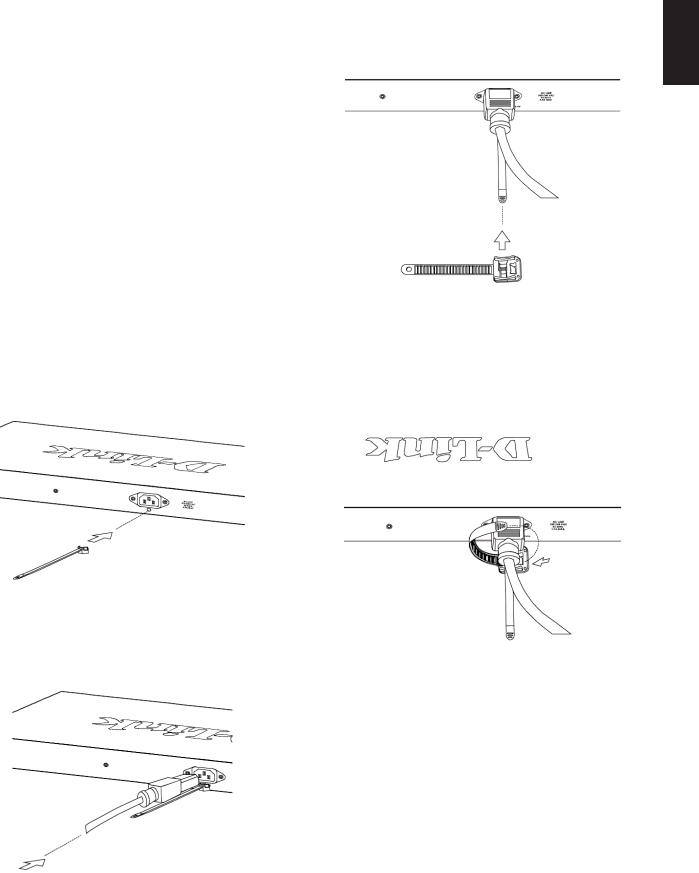
Attaching the Power Cord Retainer
To prevent the power from accidently being disconnected, it is recommend to install the included power cord retainer.
1.With the smooth side facing up, insert the tie into the opening below the power socket.
Figure 7
2.Plug the power cord into the power socket on the switch.
3.Slide the retainer through the tie until it has reached the end of the power cord.
Figure 9
4.Wrap the tie of the retainer strip around the power cord and back into the retainer to lock it. Fasten the tie until the power cord is secured.
Figure 10
ENGLISH
Connecting to the Network
The switch can be integrated into the network through one of the following connection methods:
Switch to End Node or Powered Device
Use a standard Ethernet cable to connect the switch to PCs with an 10/100/1000 Mbps RJ-45 interface, or connect and power remote IEEE 802.3af/at-
Figure 8 compliant devices, such as IP cameras or IP phones using PoE.
4
 Loading...