


DFL-800
Network
Security Firewall
This Quick Guide will guide you through the installation Process. You are
only moments away from using your new D-Link Network Security Product
Building Networks for People
DFL-800

1.Before You Begin
1.1 Check Your Package Contents....................................................................1
2.Indentifying Components
2.1 Front View.................................................................................................2
2.2 LED Indicators...........................................................................................3
2.3 Default Interface Attribute Definition.........................................................3
3.Connecting the DFL-800
3.1 Setting up Firewall to your Network........................................................4
4.Configure DFL-800
4.1 Configure your Computer’s IP..................................................................5
4.2 Using the Setup Wizard.............................................................................6
5.Appendix
5.1 How to Configure Static IP Manually on Microsoft Windows XP..............14
5.2 How to Configure Static IP Manually on Apple MAC OS X...........................15
6.WARRANTY
DFL-800 Quick Installation Guide
DFL-800
Before You Begin
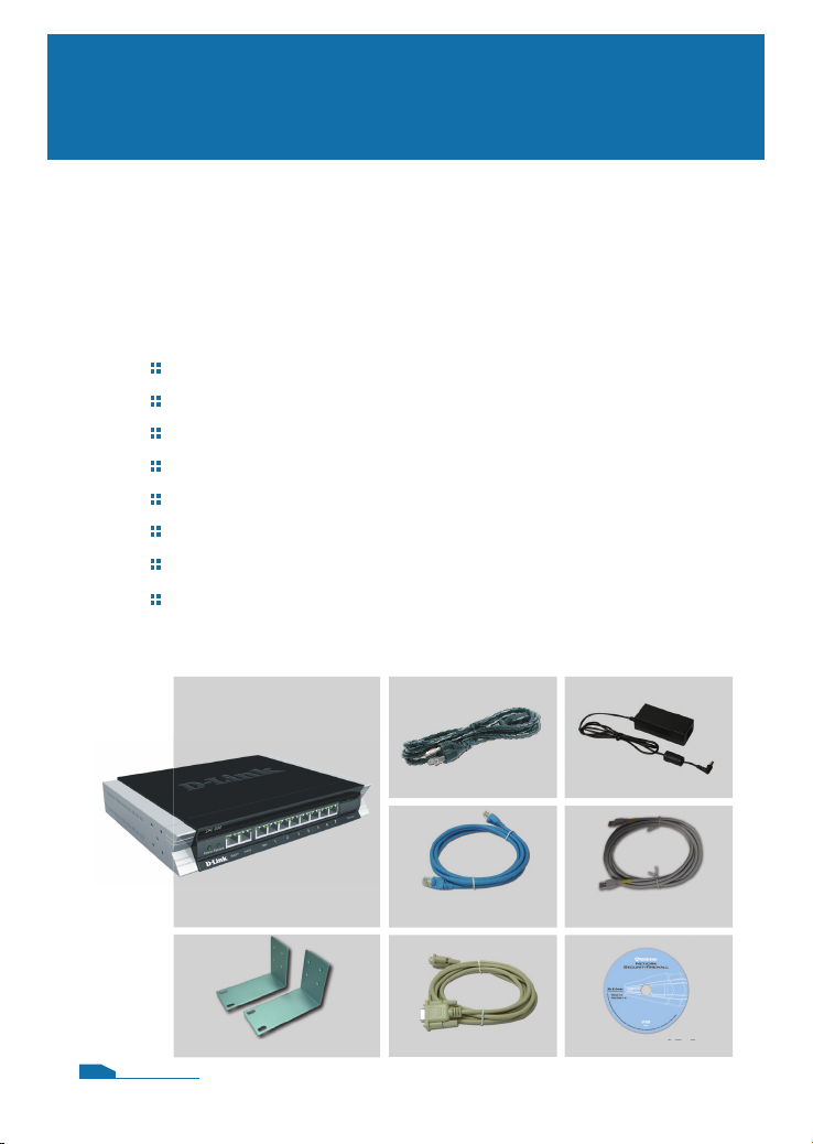
1.1 Check Your Package Contents
Your NetDefend Network Security Firewall package should
contain all the items listed below. If any of these items is found
damaged or missing in your package, report it to your reseller
immediately for replacement.
One (1) DFL-800 NetDefend™ Network Security Firewall
One (1) Power Cord
One (1) 5V DC Power Adapter
One (1) Console Cable (RS-232 cable)
One (1) Ethernet (CAT5 UTP/Straight Through) Cable
One (1) Ethernet (CAT5 UTP/Cross-over) Cable
One (1) CD-ROM (containing QIG/Manual )
Two (2) Rack Mount Brackets
1
Power Cord Power Adapter
DFL-800
Rack Mount Brackets
01
Ethernet Cable
(Straight-Through)
Console Cable CD-ROM
Ethernet Cable
(Cross-over)
Identifying Components
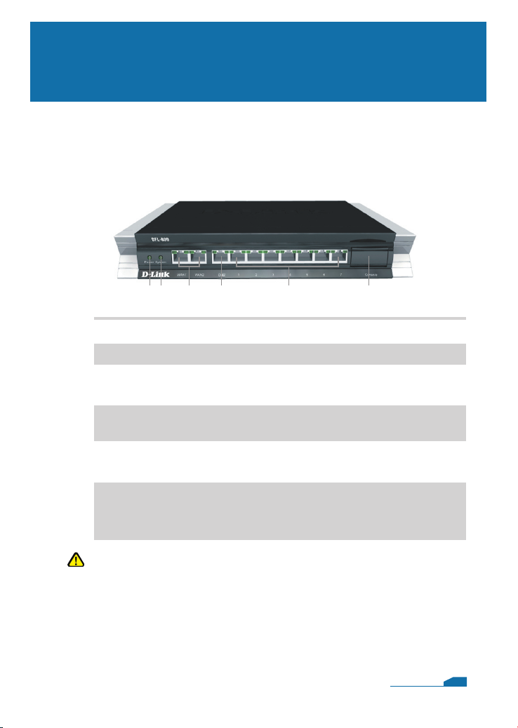
The following illustrates the front panel of the DFL-800 and
explains the front panel’s key components:
2.1 Front View
1 2 3 4 5 6
2
1. Power LED
2. System LED
3. WAN Ports
4. DMZ Port
5. LAN Ports
6. Console Port
Power indication of the DFL-800.
System status indication of the DFL-800.
These are for the connection of an Ethernet cable to a Cable
or DSL modem.
This is for the connection of an Ethernet cable to an DMZ
network.
These are for the connection of Ethernet cables to the internal
network.
Connects to RS-232 console cable that connects to PC.
The console port is hidden behind a protection coverlid that
can be opened by pulling down the lid.
Note:
None of the WAN1 and WAN2 interfaces support Auto MDI/MDI-X
(Automatic cable detection for Straight-through and Crossover
function.
02
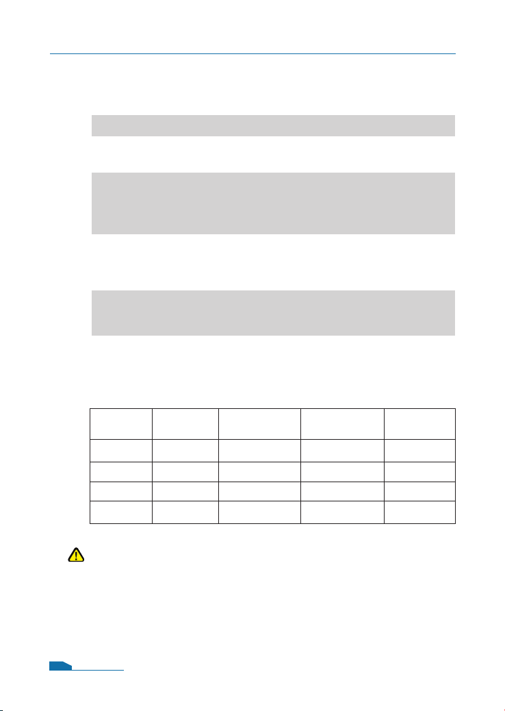
2.3 Default Interface Attribute definition
Note:
For security reason, default only allow LAN interface (192.168.1.1)
that can login into firewall GUI from Web browser. You also can
modify this configuration after login into firewall GUI. About the
detail set up procedure, please refer to the user’s manual.
DFL-800 Quick Installation Guide
03
Wording on
Front plate
Default name
in firewall
Default interface
type definition
Default interface
IP Address
Default
DHCP Status
WAN1 WAN1
Static IP 192.168.110.254/24 Disable
WAN2 WAN2
Static IP 192.168.120.254/24 Disable
DMZ DMZ Static IP 172.17.100.254/24 Disable
Ports: 1~7 LAN Static IP 192.168.1.1/24 Disable
2.2 LED Indicators
Status
Solid green
Light off
Solid green
Light off
Blinking green
Light off
Solid Green
Blinking Green
Light off
Solid green
Description
The device is powered on.
The device is powered off.
System is operating properly.
The device is not working.
System is defective, such firmware
upgrade fail.
No link
Link present
Port is sending or receiving data.
Port is operating at 10Mbps.
Port is operating at 100Mbps.
Color
Green
Green
Green
Green
LED
Power
System
Phone Jack LED
light (right)
Phone Jack LED
light (left)

3.1 Connecting Firewall to Your Network
A. First, connect the power cord to the receptor at the back panel of
the DFL-800 and then plug the other end of the power cord to a
wall outlet or power strip. Then powered on the DFL-800 using
the on/off switch. Now the Power LED will turn
ON to indicate
proper operation.
B. 1. Powered off your Cable or DSL modem; some devices may
not have a on/off switch and will require you to unplug the power
adapter. Now, the DFL-800 should be powered on and the Cable
/ DSL modem should be turned off.
2. Cable / DSL modem (Powered Off
) - DFL-800 (Powered On)
Connect an Ethernet cable to the Ethernet jack located on
the Cable / DSL modem. After the Ethernet cable is securely
connected, powered on the Cable / DSL modem by turning on
the unit or plugging in the power adapter.
3. Cable / DSL modem (
Powered On) - DFL-800 (Powered On)
Insert the other end of the Ethernet cable to one of the Ethernet
ports on the front panel of the DFL-800. The LED light above the
Enternet port will illuminate to indicate proper connection. If the
LED light is not illuminated, please go back to step B and repeat
its instructions.
C. Insert an Ethernet cable to the LAN1 port on the front panel of
the DFL-800 and connect it to a port on your network hub or
switch. The LED light above the Ethernet port on the DFL-800
will illuminate to indicate proper connection
D. Connecting the computer that you will use to configure the
DFL-800 to the network hub or switch.
Connecting the DFL-800
3
04
 Loading...