


 Loading...
DES-3226L
Release 3
Layer 2 Switch
24 Port 10/100 Managed Switch
Plus 2 Combo Gigabit Copper/SFP Ports
Web User Guide
Business Class Networking

3
Table of Contents
Table of Contents . . . . . . . . . . . . . . . . . . . . . . . . . . . . . . . . . . . . . . . . 3 List of Figures. . . . . . . . . . . . . . . . . . . . . . . . . . . . . . . . . . . . . . . . . . . 7 About This Book . . . . . . . . . . . . . . . . . . . . . . . . . . . . . . . . . . . . . . . . 9
Document Organization . . . . . . . . . . . . . . . . . . . . . . . . . . . . . . . . . . . . . . . . 9 Audience . . . . . . . . . . . . . . . . . . . . . . . . . . . . . . . . . . . . . . . . . . . . . . . . . . . . 9 Related Documentation. . . . . . . . . . . . . . . . . . . . . . . . . . . . . . . . . . . . . . . . . 9 Trademarks . . . . . . . . . . . . . . . . . . . . . . . . . . . . . . . . . . . . . . . . . . . . . . . . . 10 Copyright Statement . . . . . . . . . . . . . . . . . . . . . . . . . . . . . . . . . . . . . . . . . . 10 D-Link Offices for Registration and Warranty Service. . . . . . . . . . . . . . . . 10 Features . . . . . . . . . . . . . . . . . . . . . . . . . . . . . . . . . . . . . . . . . . . . . . . . . . . 10
Product Overview . . . . . . . . . . . . . . . . . . . . . . . . . . . . . . . . . . . . . . 13
Notes, Notices, and Cautions . . . . . . . . . . . . . . . . . . . . . . . . . . . . . . . . . . . 13 Safety Instructions. . . . . . . . . . . . . . . . . . . . . . . . . . . . . . . . . . . . . . . . . . . . 13
Safety Cautions . . . . . . . . . . . . . . . . . . . . . . . . . . . . . . . . . . . . . . . . . . . . . . . . 13 General Precautions for Rack-Mountable Products . . . . . . . . . . . . . . . . . . . . 15
Protecting Against Electrostatic Discharge . . . . . . . . . . . . . . . . . . . . . . . . 16 Switch Description . . . . . . . . . . . . . . . . . . . . . . . . . . . . . . . . . . . . . . . . . . . 16
Technical Specifications . . . . . . . . . . . . . . . . . . . . . . . . . . . . . . . . . . . . . . . . . 17
Installing the Hardware . . . . . . . . . . . . . . . . . . . . . . . . . . . . . . . . . 19
Preparing the Site for Installation . . . . . . . . . . . . . . . . . . . . . . . . . . . . . . . |
19 |
Installing the D-Link DES-3226L Switch . . . . . . . . . . . . . . . . . . . . . . . . . . |
19 |
Unpacking the Switch . . . . . . . . . . . . . . . . . . . . . . . . . . . . . . . . . . . . . . . . . . . |
20 |
Setting up the Switch . . . . . . . . . . . . . . . . . . . . . . . . . . . . . . . . . . . . . . . . . . . . |
20 |
Connecting the Switch to a Power Supply. . . . . . . . . . . . . . . . . . . . . . . . . . . . |
20 |
Installing on a Flat Surface (Free-standing Switch). . . . . . . . . . . . . . . . . . . . |
21 |
Installing in a Rack . . . . . . . . . . . . . . . . . . . . . . . . . . . . . . . . . . . . . . . . . . . . . |
22 |
Starting and Configuring the Switch. . . . . . . . . . . . . . . . . . . . . . . . . . . . . . |
23 |
Configuring for In-band Connectivity. . . . . . . . . . . . . . . . . . . . . . . . . . . . . . . 23
Using BootP or DHCP . . . . . . . . . . . . . . . . . . . . . . . . . . . . . . . . . . . . . . . . . 24 Using the RS-232 Port . . . . . . . . . . . . . . . . . . . . . . . . . . . . . . . . . . . . . . . . . 24
Configuring for Out-Of-Band Connectivity . . . . . . . . . . . . . . . . . . . . . . . . . . 25 Starting the Switch. . . . . . . . . . . . . . . . . . . . . . . . . . . . . . . . . . . . . . . . . . . . . . 26 Initial Configuration . . . . . . . . . . . . . . . . . . . . . . . . . . . . . . . . . . . . . . . . . . . . 26 Initial Configuration Procedure . . . . . . . . . . . . . . . . . . . . . . . . . . . . . . . . . . . 27 Example Session . . . . . . . . . . . . . . . . . . . . . . . . . . . . . . . . . . . . . . . . . . . . . . . 27
LED Indicators . . . . . . . . . . . . . . . . . . . . . . . . . . . . . . . . . . . . . . . . . . . . . . 29
Software Installation . . . . . . . . . . . . . . . . . . . . . . . . . . . . . . . . . . . . 31
Upgrading the Switch Firmware. . . . . . . . . . . . . . . . . . . . . . . . . . . . . . . . . 31 Quick Starting the Networking Device . . . . . . . . . . . . . . . . . . . . . . . . . . . . 32 System Information and System Setup . . . . . . . . . . . . . . . . . . . . . . . . . . . . 32
4 Web User Guide
Using the Web Interface . . . . . . . . . . . . . . . . . . . . . . . . . . . . . . . . . 37
Configuring for Web Access . . . . . . . . . . . . . . . . . . . . . . . . . . . . . . . . . . . . 37
Web Page Layout . . . . . . . . . . . . . . . . . . . . . . . . . . . . . . . . . . . . . . . . . . . . . . . 38
Starting the Web Interface . . . . . . . . . . . . . . . . . . . . . . . . . . . . . . . . . . . . . . . . 39
Command Buttons . . . . . . . . . . . . . . . . . . . . . . . . . . . . . . . . . . . . . . . . . . . . . . 40
IGMP Snooping. . . . . . . . . . . . . . . . . . . . . . . . . . . . . . . . . . . . . . . . 41
Overview . . . . . . . . . . . . . . . . . . . . . . . . . . . . . . . . . . . . . . . . . . . . . . . . . . . 41
CLI Examples . . . . . . . . . . . . . . . . . . . . . . . . . . . . . . . . . . . . . . . . . . . . . . . 41
Example #1: show igmpsnooping . . . . . . . . . . . . . . . . . . . . . . . . . . . . . . . . . . 41
Example #2: show mac-address-table igmpsnooping . . . . . . . . . . . . . . . . . . . 41
Web Examples . . . . . . . . . . . . . . . . . . . . . . . . . . . . . . . . . . . . . . . . . . . . . . . 42
Configuration Scripting . . . . . . . . . . . . . . . . . . . . . . . . . . . . . . . . . 45
Overview . . . . . . . . . . . . . . . . . . . . . . . . . . . . . . . . . . . . . . . . . . . . . . . . . . . 45
Considerations . . . . . . . . . . . . . . . . . . . . . . . . . . . . . . . . . . . . . . . . . . . . . . 45
CLI Examples . . . . . . . . . . . . . . . . . . . . . . . . . . . . . . . . . . . . . . . . . . . . . . . 45
Example #1: script . . . . . . . . . . . . . . . . . . . . . . . . . . . . . . . . . . . . . . . . . . . . . . 45
Example #2: script list and script delete . . . . . . . . . . . . . . . . . . . . . . . . . . . . . 46
Example #3: script apply running-config.scr . . . . . . . . . . . . . . . . . . . . . . . . . 46
Example #4: Creating a Configuration Script. . . . . . . . . . . . . . . . . . . . . . . . . 46
Example #5: Upload a Configuration Script . . . . . . . . . . . . . . . . . . . . . . . . . . 47
Example #6: script validate running-config.scr . . . . . . . . . . . . . . . . . . . . . . . 47
Example #7: Validate another Configuration Script . . . . . . . . . . . . . . . . . . . . 48
Port Mirroring . . . . . . . . . . . . . . . . . . . . . . . . . . . . . . . . . . . . . . . . 49
Overview . . . . . . . . . . . . . . . . . . . . . . . . . . . . . . . . . . . . . . . . . . . . . . . . . . . 49
CLI Examples . . . . . . . . . . . . . . . . . . . . . . . . . . . . . . . . . . . . . . . . . . . . . . . 49
Example #1: show monitor session . . . . . . . . . . . . . . . . . . . . . . . . . . . . . . . . . 49
Example #2: show port all . . . . . . . . . . . . . . . . . . . . . . . . . . . . . . . . . . . . . . . . 49
Example #3: show port interface . . . . . . . . . . . . . . . . . . . . . . . . . . . . . . . . . . . 50
Example #4: show monitor session 1. . . . . . . . . . . . . . . . . . . . . . . . . . . . . . . . 50
Example #5: (Config) monitor session 1 mode . . . . . . . . . . . . . . . . . . . . . . . . 50
Example #6: (Config) monitor session 1 source interface. . . . . . . . . . . . . . . . 51
Web Examples . . . . . . . . . . . . . . . . . . . . . . . . . . . . . . . . . . . . . . . . . . . . . . . 51
Syslog . . . . . . . . . . . . . . . . . . . . . . . . . . . . . . . . . . . . . . . . . . . . . . . . 53
Overview . . . . . . . . . . . . . . . . . . . . . . . . . . . . . . . . . . . . . . . . . . . . . . . . . . . 53
Persistent Log Files . . . . . . . . . . . . . . . . . . . . . . . . . . . . . . . . . . . . . . . . . . . . . 53
Interpreting Log Files . . . . . . . . . . . . . . . . . . . . . . . . . . . . . . . . . . . . . . . . . . . 53
CLI Examples . . . . . . . . . . . . . . . . . . . . . . . . . . . . . . . . . . . . . . . . . . . . . . . 54
Example #1: show logging. . . . . . . . . . . . . . . . . . . . . . . . . . . . . . . . . . . . . . . . 54
Example #2: show logging persistent . . . . . . . . . . . . . . . . . . . . . . . . . . . . . . . 54
Example #3: show logging traplogs . . . . . . . . . . . . . . . . . . . . . . . . . . . . . . . . 54
Example #4: logging port configuration . . . . . . . . . . . . . . . . . . . . . . . . . . . . . 55
Example #5: show logging hosts . . . . . . . . . . . . . . . . . . . . . . . . . . . . . . . . . . . 55
Web Examples . . . . . . . . . . . . . . . . . . . . . . . . . . . . . . . . . . . . . . . . . . . . . . . 56
5
Traceroute. . . . . . . . . . . . . . . . . . . . . . . . . . . . . . . . . . . . . . . . . . . . . 57
Traceroute Overview. . . . . . . . . . . . . . . . . . . . . . . . . . . . . . . . . . . . . . . . . . 57 CLI Example . . . . . . . . . . . . . . . . . . . . . . . . . . . . . . . . . . . . . . . . . . . . . . . . 57
Virtual LANs . . . . . . . . . . . . . . . . . . . . . . . . . . . . . . . . . . . . . . . . . . 59
VLAN Configuration Example . . . . . . . . . . . . . . . . . . . . . . . . . . . . . . . . . . 59
CLI Examples . . . . . . . . . . . . . . . . . . . . . . . . . . . . . . . . . . . . . . . . . . . . . . . . . 60 Graphical User Interface . . . . . . . . . . . . . . . . . . . . . . . . . . . . . . . . . . . . . . . . 62
Private Edge VLANs . . . . . . . . . . . . . . . . . . . . . . . . . . . . . . . . . . . . . . . . . . 62
CLI Example . . . . . . . . . . . . . . . . . . . . . . . . . . . . . . . . . . . . . . . . . . . . . . . . . . 62
Class of Service (CoS) . . . . . . . . . . . . . . . . . . . . . . . . . . . . . . . . . . . 63
CoS Queue Mapping. . . . . . . . . . . . . . . . . . . . . . . . . . . . . . . . . . . . . . . . . . 63
CLI Examples . . . . . . . . . . . . . . . . . . . . . . . . . . . . . . . . . . . . . . . . . . . . . . . . . 64
Example #1 classofservice dot1p-mapping . . . . . . . . . . . . . . . . . . . . . . . . . 64 Example #2: show classofservice dot1p-mapping . . . . . . . . . . . . . . . . . . . . 64 Example #3: show classofservice trust . . . . . . . . . . . . . . . . . . . . . . . . . . . . 64
Traffic Shaping and Rate Limiting . . . . . . . . . . . . . . . . . . . . . . . . . . . . . . . 64 traffic-shape. . . . . . . . . . . . . . . . . . . . . . . . . . . . . . . . . . . . . . . . . . . . . . . . . . . 64 rate-limit . . . . . . . . . . . . . . . . . . . . . . . . . . . . . . . . . . . . . . . . . . . . . . . . . . . . . 65
Example #4 (Interface Config) traffic-shape . . . . . . . . . . . . . . . . . . . . . . . . 65 Example #5 show interfaces cos-queue slot/port . . . . . . . . . . . . . . . . . . . . . 65
Web Example . . . . . . . . . . . . . . . . . . . . . . . . . . . . . . . . . . . . . . . . . . . . . . . . . . 66
Link Aggregation . . . . . . . . . . . . . . . . . . . . . . . . . . . . . . . . . . . . . . . 67
Link Aggregation. . . . . . . . . . . . . . . . . . . . . . . . . . . . . . . . . . . . . . . . . . . . . 67
Example #1: Link Aggregation Configuration Example . . . . . . . . . . . . . . . . . 67
Limited Warranty (USA only) . . . . . . . . . . . . . . . . . . . . . . . . . . . . 71 Registration . . . . . . . . . . . . . . . . . . . . . . . . . . . . . . . . . . . . . . . . . . . 75 Technical Support . . . . . . . . . . . . . . . . . . . . . . . . . . . . . . . . . . . . . . 77 International Offices . . . . . . . . . . . . . . . . . . . . . . . . . . . . . . . . . . . 103 Appendix A – Cables and Connectors . . . . . . . . . . . . . . . . . . . . A-1 Appendix B – Connector Pinouts . . . . . . . . . . . . . . . . . . . . . . . . B-1 Appendix C– Cable Lengths and Wavelengths . . . . . . . . . . . . . C-1
6 Web User Guide

7
List of Figures |
|
Figure 1. D-Link DES-3226L - Front View ......................................................... |
19 |
Figure 2. Connecting Power Cable ....................................................................... |
21 |
Figure 3. Prepare the Switch for Installation on a Desktop or Shelf .................... |
21 |
Figure 4. Attaching the Brackets .......................................................................... |
22 |
Figure 5. Installing the DES-3226L in a Rack...................................................... |
23 |
Figure 6. D-Link DES-3226L - Front View ......................................................... |
25 |
Figure 7. Connecting to the Console Port............................................................. |
26 |
Figure 8. Firmware Download for D-Link DES-3226L ....................................... |
31 |
Figure 9. Web Interface Panel-Example .............................................................. |
38 |
Figure 10. Configuring an SNMP V3 User Profile .............................................. |
39 |
Figure 11. IGMP Snooping - Global Configuration and Status Page................... |
42 |
Figure 12. IGMP Snooping - Interface Configuration Page................................. |
43 |
Figure 13. IGMP Snooping - VLAN Status Page................................................. |
43 |
Figure 14. System - Port Summary....................................................................... |
51 |
Figure 15. System - Port - Multiple Port Mirroring.............................................. |
52 |
Figure 16. Persistent Log Configuration Page...................................................... |
56 |
Figure 17. Persistent Logs .................................................................................... |
56 |
Figure 18. VLAN example network diagram ....................................................... |
60 |
Figure 19. CoS Interface Configuration ............................................................... |
66 |
Figure 20. LAG example network diagram .......................................................... |
68 |
8 Web User Guide

About This Book 9
About This Book
This document describes the D-Link™ DES-3226L hardware and software installation process, and provides an understanding of the CLI and Web configuration options for features in this release. It provides basic information to install, configure, and operate the
D-Link DES-3226L switch. For more information, go to the D-Link Support web site at http://support.dlink.com/ for the latest updates on documentation and software.
Document Organization
This document contains sections to help you:
zInstall the D-Link DES-3226L switch and prepare it for installing the D-Link DES-3226L software package
zInstall the D-Link DES-3226L software
This document also describes the use of the CLI and web interfaces and gives configuration information about the following:
zIGMP Snooping
zConfiguration Scripting
zPort Mirroring
zSyslog
zTraceroute
zVLANs
zLink Aggregation
zClass of Service
Warranty, registration, and international technical support contact information appear at the end of the document.
Audience
Use this guide if you are:
zNetwork manager familiar with network management concepts and terminology.
zSystem administrator who is responsible for configuring and operating a network.
zLevel 1 and Level 2 Support.
You should have a basic knowledge of Ethernet and networking concepts.
Related Documentation
The D-Link DES-3226L CLI Guide provides information about the CLI commands used to configure the switch. The document provides command mode descriptions and descriptions, syntax, and default values for individual commands.

10 Web User Guide
Trademarks
Contents subject to change without prior notice.
D-Link is a registered trademark of D-Link Corporation/D-Link Systems, Inc. All other trademarks belong to their respective proprietors.
Copyright Statement
Copyright © 2006 D-Link Corporation D-Link Systems, Inc.
No part of this publication may be reproduced in any form or by any means or used to make any derivative such as translation, transformation, or adaptation without permission from D-Link Corporation/D-Link Systems Inc., as stipulated by the United States Copyright Act of 1976.
D-Link Offices for Registration and Warranty Service
The Registration section at the back of this manual contains a web address for registering this product.
To obtain an RMA number for warranty service as to a hardware product, or to obtain warranty service as to a software product, contact the D-Link office nearest you. An address/telephone/fax/e-mail/Web site list of D-Link offices is provided in the back of this manual.
Features
This version of D-Link’s networking software includes the following features:
zLayer 2 Features
IEEE 802.1Q VLAN operation
VLAN Tagging
Link Aggregation
Bridging Support
Multiple Spanning Tree
Rapid Spanning Tree
Spanning Tree
Virtual LANs/Port-based VLANs
Ethernet Priority with User Provisioning and Mapping
Port Based Authentication
Flow Control
IGMP Snooping
Port Mirroring
Broadcast Storm Control
Multicast Storm control
XMODEM
About This Book 11
Support for:
User Datagram Protocol (UDP)
Trivial File Transfer Protocol (TFTP)
Internet Protocol (IP)
Internet Control Message Protocol (ICMP)
TCP
Bootstrap Protocol (BootP)
Interoperability between BootP and Dynamic Host Configuration Protocol (DHCP)
DHCP Client
DHCP Options and BootP Vendor Extensions
RADIUS Client
RADIUS Accounting
RADIUS Attributes for Tunnel Protocol support
RADIUS Extensions
RADIUS Support for EAP
802.1x RADIUS Usage Guidelines
Private Edge VLANs
zQuality of Service
zManagement Features
Telnet
Telnet Option
SMI v1, SMI v2
Textual Conventions for SMI v2
Conformance statements for SMI v2
Simple Network Management Protocol (SNMP)
Community-based SNMP v2
Protocol Operations for SNMP v2
Transport Mappings for SNMP v2
Management Information Base for SNMP v2
Coexistence between SNMP v1 and SNMP v2
SNMP Framework MIB
Architecture for Describing SNMP Management Frameworks
Message Processing and Dispatching
View-based Access Control Model
Coexistence between SNMP v1, v2, and v3
SNMB v3 Applications
User Based Security Model for SNMP v3
Concise MIB Definitions
HTML/2.0 Forms with File Upload Extensions
HTTP/1.1 Protocol per draft-ietf-http-v11-spec-rev-03
Transparent Content Negotiation
Remote Variant Selection
HTML 4.0 Specification
Java and Java Script 1.3
Configurable Management VLAN ID
Industry Standard CLI
Logging
Configuration Migration
12Web User Guide
Layer 2 MIBs
MIB-II
Bridge MIB
Ethernet-like MIB
The Interfaces Group MIB using SMI v2
RADIUS Authentication Client MIB
RADIUS Accounting MIB
VLAN and Ethernet Priority MIB
RMON Groups 1,2,3, and 9
Internet Addresses MIB
IANA-ifType-MIB
IEEE 802.1x MIB (IEEE8021-PAE-MIB)
IEEE 802.3AD MIB (IEEE8021-AD-MIB
Enterprise MIB - Support for all managed objects not contained in standardsbased MIBs according to the functions listed above

Product Overview 13
Product Overview
This section contains an overview and technical specifications of the D-Link DES-3226L switch.
The D-Link DES-3226L is a high-performance Fast Ethernet switch that provides 24 10/100 Mbps switched ports with two combo gigabit copper/Small Form Factor Pluggable (SFP) ports. The switched 10/100 Mbps ports are ideal for segmenting networks into small, connected sub networks for superior performance, enabling the most demanding multimedia and imaging applications over the network. The two fixed-in gigabit copper ports support 10/ 100/1000BASE-T speed. There are also two SFP ports that provide optional fiber gigabit uplinks. These SFP ports are associated with the gigabit copper ports, so that if the SFP ports are used, the gigabit copper ports are disabled.
Notes, Notices, and Cautions
A NOTE indicates important information that helps you make better use of your device. A CAUTION  indicates a potential for property damage, personal injury, or death.
Safety Instructions
Use the following safety guidelines to ensure your own personal safety and to help protect your system from potential damage. Throughout this safety section, the caution icon (  ) is used to indicate cautions and precautions that you need to review and follow.
Safety Cautions
To reduce the risk of bodily injury, electrical shock, fire, and damage to the equipment, observe the following precautions.
zObserve and follow service markings.
Do not service any product except as explained in your system documentation.
Opening or removing covers that are marked with the triangular symbol with a lightning bolt may expose you to electrical shock.
Only a trained service technician should service components inside these compartments.
zIf any of the following conditions occur, unplug the product from the electrical outlet and replace the part or contact your trained service provider:
The power cable, extension cable, or plug is damaged.
An object has fallen into the product.
The product has been exposed to water.
The product has been dropped or damaged.
The product does not operate correctly when you follow the operating instructions.
zKeep your system away from radiators and heat sources. Also, do not block cooling vents.
zDo not spill food or liquids on your system components, and never operate the product in a wet environment. If the system gets wet, see the appropriate section in your troubleshooting guide or contact your trained service provider.
14 Web User Guide
zDo not push any objects into the openings of your system. Doing so can cause fire or electric shock by shorting out interior components.
zUse the product only with approved equipment.
zAllow the product to cool before removing covers or touching internal components.
zOperate the product only from the type of external power source indicated on the electrical ratings label. If you are not sure of the type of power source required, consult your service provider or local power company.
zTo help avoid damaging your system, be sure the voltage selection switch (if provided) on the power supply is set to match the power available at your location:
115 volts (V)/60 hertz (Hz) in most of North and South America and some Far Eastern countries such as South Korea and Taiwan
100 V/50 Hz in eastern Japan and 100 V/60 Hz in western Japan
230 V/50 Hz in most of Europe, the Middle East, and the Far East
zAlso, be sure that attached devices are electrically rated to operate with the power available in your location.
zUse only approved power cable(s). If you have not been provided with a power cable for your system or for any AC powered option intended for your system, purchase a power cable that is approved for use in your country. The power cable must be rated for the product and for the voltage and current marked on the product's electrical ratings label. The voltage and current rating of the cable should be greater than the ratings marked on the product.
zTo help prevent electric shock, plug the system and peripheral power cables into properly grounded electrical outlets.
zThese cables are equipped with three-prong plugs to help ensure proper grounding. Do not use adapter plugs or remove the grounding prong from a cable. If you must use an extension cable, use a 3-wire cable with properly grounded plugs.
zObserve extension cable and power strip ratings. Make sure that the total ampere rating of all products plugged into the extension cable or power strip does not exceed 80 percent of the ampere ratings limit for the extension cable or power strip.
zTo help protect your system from sudden, transient increases and decreases in electrical power, use a surge suppressor, line conditioner, or uninterruptible power supply (UPS).
zPosition system cables and power cables carefully; route cables so that they cannot be stepped on or tripped over. Be sure that nothing rests on any cables.
zDo not modify power cables or plugs. Consult a licensed electrician or your power company for site modifications.
zAlways follow your local/national wiring rules.
zWhen connecting or disconnecting power to hot-pluggable power supplies, if offered with your system, observe the following guidelines:
Install the power supply before connecting the power cable to the power supply.
Unplug the power cable before removing the power supply.
If the system has multiple sources of power, disconnect power from the system by unplugging all power cables from the power supplies.
zMove products with care; ensure that all casters and/or stabilizers are firmly connected to the system. Avoid sudden stops and uneven surfaces.

Product Overview 15
General Precautions for Rack-Mountable Products
Observe the following precautions for rack stability and safety. Also, refer to “Installing in a Rack” on page 22 and the rack installation documentation accompanying the rack for specific caution statements and procedures.
zSystems are considered to be components in a rack. Thus, component refers to any system as well as to various peripherals or supporting hardware.
Caution:  CAUTION: Installing systems in a rack without the front and side stabilizers installed could cause the rack to tip over, potentially resulting in bodily injury under certain circumstances. Therefore, always install the stabilizers before installing components in the rack. After installing system/ components in a rack, never pull more than one component out of the rack on its slide assemblies at one time. The weight of more than one extended component could cause the rack to tip over and may result in serious injury.
zBefore working on the rack, make sure that the stabilizers are secured to the rack, extended to the floor, and that the full weight of the rack rests on the floor. Install front and side stabilizers on a single rack or front stabilizers for joined multiple racks before working on the rack.
zAlways load the rack from the bottom up, and load the heaviest item in the rack first.
zMake sure that the rack is level and stable before extending a component from the rack.
zUse caution when pressing the component rail release latches and sliding a component into or out of a rack; the slide rails can pinch your fingers.
zAfter a component is inserted into the rack, carefully extend the rail into a locking position and then slide the component into the rack.
zDo not overload the AC supply branch circuit that provides power to the rack. The total rack load should not exceed 80 percent of the branch circuit rating.
zEnsure that proper airflow is provided to components in the rack.
zDo not step on or stand on any component when servicing other components in a rack.
NOTE:A qualified electrician must perform all connections to DC power and to safety grounds. All electrical wiring must comply with applicable local or national codes and practices.
Caution:  CAUTION: Never defeat the ground conductor or operate the equipment in the absence of a suitably installed ground conductor. Contact the appropriate electrical inspection authority or an electrician if you are uncertain that suitable grounding is available.
 CAUTION: The system chassis must be positively grounded to the rack cabinet frame. Do not attempt to connect power to the system until grounding cables are connected. Completed power and safety ground wiring must be inspected by a qualified electrical inspector. An energy hazard will exist if the safety ground cable is omitted or disconnected.

16 Web User Guide
Protecting Against Electrostatic Discharge
Static electricity can harm delicate components inside your system. To prevent static damage, discharge static electricity from your body before you touch any of the electronic components, such as the microprocessor. You can do so by periodically touching an unpainted metal surface on the chassis.
You can also take the following steps to prevent damage from electrostatic discharge (ESD):
1.When unpacking a static-sensitive component from its shipping carton, do not remove the component from the antistatic packing material until you are ready to install the component in your system. Just before unwrapping the antistatic packaging, be sure to discharge static electricity from your body.
2.When transporting a sensitive component, first place it in an antistatic container or packaging.
3.Handle all sensitive components in a static-safe area. If possible, use antistatic floor pads, workbench pads and an antistatic grounding strap.
Switch Description
D-Link's DES-3226L switch is a high port-density Layer 2 switch that combines ultimate performance with fault tolerance, security, and management functions with flexibility and ease-of-use.
The D-Link DES-3226L switch has a combination of 1000BASE-T ports and SFP ports that may be used in uplinking various network devices to the switch (including PCs, hubs, and other switches) to provide a gigabit Ethernet uplink in full-duplex mode. The Small Form Factor Pluggable (SFP) combo ports are to be used with fiber-optical transceiver cabling in order to uplink various other networking devices for a gigabit link that may span great distances. These SFP ports support full-duplex transmissions, have auto-negotiation, and can be used with DEM -310GT (1000BASELX) and DEM-311GT (1000BASE-SX) transceivers.
NOTE:The SFP combo ports on the switch cannot be used simultaneously with the corresponding 1000BASE-T ports. If both ports are in use at the same time (for example, port 25 of the SFP and port 25 of the 1000BASE-T), the SFP ports will take priority over the combo ports and render the 1000BASE-T ports inoperable.

Product Overview 17
Technical Specifications
This section displays specifications for the D-Link DES-3226L switch as follows:
zGeneral specifications
zPhysical and environmental specifications
zPerformance
Table 1. General Specifications
Specifications |
Description |
|
|
Standards |
IEEE 802.3 10BASE-T Ethernet |
|
IEEE 802.3u 100BASE-TX Fast Ethernet |
|
IEEE 802.3ab 1000BASE-T Gigabit Ethernet |
|
IEEE 802.3x Full Duplex Flow Control |
|
IEEE 802.3z 1000BASE-SX/LX Gigabit Ethernet |
|
|
Protocol |
CSMA/CD |
|
|
Data Transfer Rate |
Ethernet: 10Mbps (half duplex), 20Mbps (full-duplex) |
|
Fast Ethernet: 100Mbps (half duplex), 200Mbps (full-duplex) |
|
Gigabit Ethernet: 2000Mbps (full-duplex) |
|
|
Topology |
Star |
|
|
Network Cables |
10BASET: 2-pair UTP Cat. 3, 4, 5; up to 100m |
|
100BASE-TX: 2-pair UTP Cat. 5; up to 100m |
|
1000BASE-T: 4-pair UTP Cat. 5; up to 100m |
|
Fiber module: mini-GBIC Fiber module |
|
|
Number of Ports |
24 × 10/100 Mbps Auto-MDIX RJ-45 ports |
|
2 × combo gigabit copper/SFP ports |
|
|
Table 2. Physical and Environmental Factors |
|
Feature |
Description |
|
|
AC inputs |
100-240V AC, 50/60 Hz internal universal power supply |
|
|
Power Consumption |
9.5 Watts (Max) |
|
|
Temperature |
Operating: 0 ~ 50° C, Storage: -10 ~ 70° C |
|
|
Humidity |
Operating: 10% ~ 90%, Storage: 5% ~ 90% |
|
|
Dimensions |
440 x 210 x 44 mm/17.4 x 8.3 x 1.8 inches (W x D x H) |
|
|
EMI: |
FCC Class A, CE Mark Class A, VCCI Class A |
|
|
Safety: |
CUL, LVD |
|
|
18 Web User Guide
Table 3. Performance
Feature |
Description |
|
|
Transmits Method: |
Store-and-forward |
|
|
Filtering Address Table: |
8K entries per device |
|
|
Packet Filtering/Forwarding Rate: |
10Mbps Ethernet: 14,880/pps |
|
100Mbps Fast Ethernet: 148,800/pps |
|
1000Mbps Gigabit Ethernet: 1,488,000/pps |
|
|
MAC Address Learning: |
Automatic update |
|
|
Transmits Method: |
Store-and-forward |
|
|
RAM Buffer: |
256K bytes per device |
|
|
Installing the Hardware 19
Installing the Hardware
This chapter provides instructions for installing the D-Link DES-3226L switch hardware. The following sections describe this installation process.
Preparing the Site for Installation
D-Link DES-3226L switches can be mounted in a standard 48.26-cm (19-inch) rack or left freestanding (placed on a tabletop).
Before installing the switch or switches, make sure that the chosen installation location meets the following site requirements:
zPower — The switch is installed near an easily accessible 100–250 VAC, 50–60 Hz outlet.
zGeneral — The power supply is correctly installed by checking that the LEDs on the front panel are illuminated.
zClearance — There is adequate frontal clearance for operator access. Allow clearance for cabling, power connections, and ventilation.
zCabling — The cabling is routed to avoid sources of electrical noise such as radio transmitters, broadcast amplifiers, power lines, and fluorescent lighting fixtures.
zAmbient — The ambient switch operating temperature range is 0 to 50ºC (32 to 122ºF) at a relative humidity of 10 to 90 percent, non-condensing.
Installing the D-Link DES-3226L Switch
This section discusses installing the D-Link DES-3226L switch.
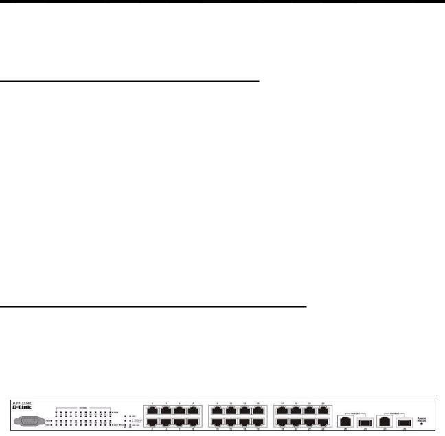
NOTE:Before unpacking the switch, inspect the container and report any evidence of damage.
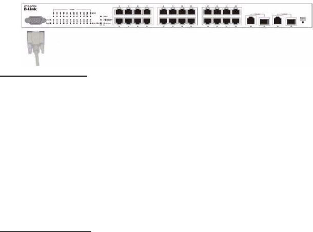
Figure 1. D-Link DES-3226L - Front View

20 Web User Guide
Unpacking the Switch
1.Place the container on a clean flat surface and cut all straps securing the container.
2.Unpack the DES-3226L switch from the box. Save the packing material and box. Open the shipping carton of the switch and carefully unpack its contents. The carton should contain the following items:
One DES-3226L stand-alone switch
One AC power cord
Rack mount kit (two brackets and screws)
Four rubber feet with adhesive backing
RS-232 console cable
Manual CD
NOTE:If any item is found missing or damaged, please contact your local D-Link Reseller for replacement.
3.Carefully remove the switch from the container and place it on a secure and clean surface. See Section “Setting up the Switch.”
4.Remove all packing material.
5.Inspect the product and accessories for damage. Report any damage immediately.
Setting up the Switch
The site where you install the switch may greatly affect its performance. Please follow these guidelines for setting up the switch.
zInstall the switch on a sturdy, level surface that can support at least 6.6 lb. (3 kg) of weight. Do not place heavy objects on the switch.
zEnsure that the power outlet is within 1.82 meters (6 feet) of the switch.
zVisually inspect the power cord and see that it is fully secured to the AC power port. See
Section “Connecting the Switch to a Power Supply.”
zMake sure that there is proper heat dissipation from and adequate ventilation around the switch. Leave at least 10 cm (4 inches) of space at the front and rear of the switch for ventilation.
zInstall the switch in a fairly cool and dry place for the acceptable temperature and humidity operating ranges.
zInstall the switch in a site free from strong electromagnetic field generators (such as motors), vibration, dust, and direct exposure to sunlight.
zWhen installing the switch on a level surface, attach the rubber feet to the bottom of the device. The rubber feet cushion the switch, protect the casing from scratches, and prevent it from scratching other surfaces.
Connecting the Switch to a Power Supply
1.Connect one end of the AC power cable to the AC power connector located on the back panel (see Figure 2) and the other end into the local power source outlet.
NOTE:Do not connect the power cable to a grounded AC outlet at this time. Connect the switch to a power source as described in the step detailed in “Starting and Configuring the Switch” on page 23."
Installing the Hardware 21
NOTE:Read the safety information in the Product Information Guide as well as the safety information for other switches that connect to or support the switch.
Figure 2. Connecting Power Cable
Connect a power cable to the DES-3226L.
2.After the switch is powered on, the LED indicators momentarily blink and then display solidly. This blinking of the LED indicators represents a reset of the system.
Caution:  CAUTION: As a precaution, in the event of a power failure, unplug the switch. When power is resumed, plug the switch back into the wall outlet.
Installing on a Flat Surface (Free-standing Switch)
Install the switch on a flat surface if you are not installing it in a rack. The surface must be able to support the weight of the switch and the switch cables.
1. Attach the self-adhesive rubber pads on each location marked on the bottom of the chassis.
Figure 3. Prepare the Switch for Installation on a Desktop or Shelf
2.Set the switch on a flat surface, leaving 5.08 cm (2 inches) on each side and 12.7 cm (5 inches) at the back.
3.Make sure that the switch has proper ventilation.
22 Web User Guide
Installing in a Rack
The D-Link DES-3226L switch can be mounted in a standard 19” rack.
Caution: |
CAUTION: Do not use rack mounting kits to suspend the switch from |
|
under a table or desk or attach it to a wall. |
Caution: |
CAUTION: Disconnect all cables from the switch before continuing. |
|
Remove all self-adhesive pads from the underside of the switch if they have been |
|
attached. |
Caution: |
CAUTION: When mounting multiple switches into a rack, mount the |
|
switches from the bottom up. |
Caution: |
CAUTION: Make sure that the supplied rack bolts fit the pre-threaded |
|
holes in the rack. |
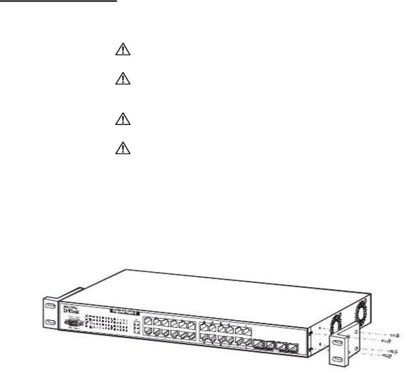
1.Place the supplied rack-mounting bracket on one side of the switch, ensuring that the mounting holes on the switch line up to the mounting holes in the rack-mounting bracket. Figure 4 illustrates where to mount the brackets.
Figure 4. Attaching the Brackets
Note: This figure is not an actual DES-3226L. It is used for explanatory purposes only.
2.Insert the supplied bolts into the rack-mounting holes and tighten with a screwdriver.
3.Repeat the process for the rack-mounting bracket on the other side of the switch.
4.Insert the switch into the 48.26 cm (19 inch) rack, ensuring that the rack-mounting holes on the switch line up to the mounting holes in the rack.
Installing the Hardware 23
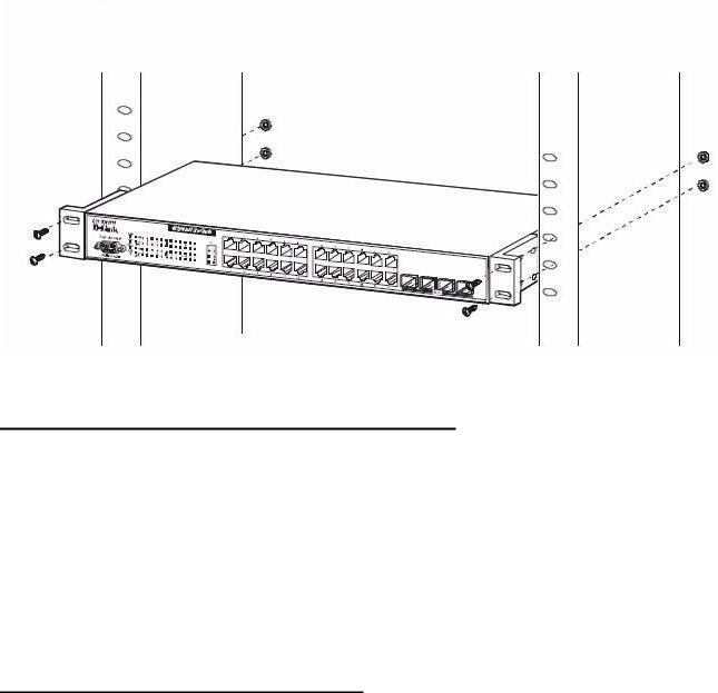
Figure 5. Installing the DES-3226L in a Rack
Note: This figure is not an actual DES-3226L. It is used for explanatory purposes only.
5.Secure the switch to the rack with either the rack bolts or cage nuts and cage nut bolts with washers (depending on the kind of rack you have). Fasten the bolts on bottom before fastening the bolts on top. Make sure that the ventilation holes are not obstructed.
Starting and Configuring the Switch
After completing all external connections, connect a terminal to a switch to configure the switch. Additional advanced functions are described in the DES-3226L CLI Guide or check the D-Link Support web site at http://support.dlink.com/ for the latest updates on documentation and software.
NOTE:Read the release notes for this product before proceeding. You can download the release notes from the D-Link Support website at
http://support.dlink.com/.
NOTE:We recommend that you obtain the most recent version of the user documentation from the D-Link Support website at http://support.dlink.com/.
Configuring for In-band Connectivity
In-band connectivity allows you to access the D-Link DES-3226L from a remote workstation using the Ethernet network. To use in-band connectivity, you must configure the DES-3226L with IP information (IP address, subnet mask, and default gateway).
Configure for In-band connectivity using one of the following methods:
zBootP or DHCP
zRS-232 port
24 Web User Guide
Using BootP or DHCP
You can assign IP information initially over the network or over the Ethernet service port through BootP or DHCP. The DES-3226L has BootP enabled.
You need to configure the BootP or DHCP server with information about the DES-3226L — obtain this information through the serial port connection using the show network command. Set up the server with the following values:
IP Address
Unique IP address for the DES-3226L. Each IP parameter is made up of four decimal numbers, ranging from 0 to 255. The default for all IP parameters is zeroes (0.0.0.0).
Subnet
Subnet mask for the LAN
gateway
IP address of the default router, if the switch is a node outside the IP range of the LAN
MAC Address
MAC address of the DES-3226L
When you connect the DES-3226L to the network for the first time after setting up the BootP or DHCP server, it is configured with the information supplied above. The DES-3226L is ready for in-band connectivity over the network.
If you do not use BootP or DHCP, access the switch through the RS-232 port, and configure the network information as described below.
Using the RS-232 Port
You can use a locally or remotely attached terminal to configure in-band management through the RS-232 port.
1.To use a locally attached terminal, attach one end of a null-modem serial cable to the RS-232 port of the switch and the other end to the COM port of the terminal or workstation.
For remote attachment, attach one end of the serial cable to the RS-232 port of the switch and the other end to the modem.
NOTE:You must use the cable that was shipped with the D-Link DES-3226L.
2.Set up the terminal for VT100 terminal emulation.
A.Set the terminal ON.
B.Launch the VT100 application.
C.Configure the COM port as follows:
I.Set the data rate to 115,200 baud.
II. Set the data format to 8 data bits, 1 stop bit, and no parity.
III. Set the flow control to none.
IV. Select the proper mode under Properties.
V.Select Terminal keys.
3.The Log-in User prompt displays when the terminal interface initializes.
Enter an approved user name and password. The default is admin for the user name and the pass-
Installing the Hardware 25
word is blank.
The DES-3226L is installed and loaded with the default configuration.
4.Reduce network traffic by turning off the Network Configuration Protocol. Enter the following command:
configure network protocol none
5.Set the IP address, subnet mask, and gateway address by issue the following command: config network parms ipaddress netmask gateway
IP Address
Unique IP address for the DES-3226L. Each IP parameter is made up of four decimal numbers, ranging from 0 to 255. The default for all IP parameters is zeroes (0.0.0.0).
Subnet
Subnet mask for the LAN.
gateway
IP address of the default router, if the switch is a node outside the IP range of the LAN.
6.To enable these changes to be retained during a reset of the DES-3226L, type Ctrl-Z to return to the main prompt, type save config at the main menu prompt, and type y to confirm the changes.
7.To view the changes and verify in-band information, issue the command: show network.
8.The DES-3226L is configured for in-band connectivity and ready for Web-based management.
Configuring for Out-Of-Band Connectivity
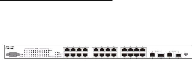
To monitor and configure the switch using out-of-band connectivity, use the console port to connect the switch to a terminal desktop system running terminal emulation software. The console port connector is a male DB-9 connector, implemented as a data terminal equipment (DTE) connector.
Figure 6. D-Link DES-3226L - Front View
The following hardware is required to use the console port:
zVT100-compatible terminal, or a desktop, or a portable system with a serial port running VT100 terminal emulation software.
zAn RS-232 crossover cable with a female DB-9 connector for the console port and the appropriate connector for the terminal.
Perform the following tasks to connect a terminal to the switch console port using out-of-band connectivity:
1.Connect an RS-232 crossover cable to the terminal running VT100 terminal emulation software.
2.Configure the terminal emulation software as follows:
A.Select the appropriate serial port (serial port 1 or serial port 2) to connect to the console.
B.Set the data rate to 115,200 baud.
26Web User Guide
C.Set the data format to 8 data bits, 1 stop bit, and no parity.
D.Set the flow control to none.
E.Select the proper mode under Properties.
F.Select Terminal keys.
NOTE:When using HyperTerminal with Microsoft Windows 2000, make sure that you have Windows 2000 Service Pack 2 or later installed. With Windows 2000 Service Pack 2, the arrow keys function properly in HyperTerminal's VT100 emulation. Go to www.microsoft.com for more information on Windows 2000 service packs.
3.Connect the female connector of the RS-232 crossover cable directly to the switch console port, and tighten the captive retaining screws. The DES-3226L series console port is located on the front panel as shown in Figure 7.
Figure 7. Connecting to the Console Port
Starting the Switch
1.Make sure that the switch console port is connected to a VT100 terminal or VT100 terminal emulator via the RS-232 crossover cable.
2.Locate an AC power receptacle.
3.Deactivate the AC power receptacle.
4.Connect the switch to the AC receptacle.
5.Activate the AC power receptacle.
When the power is turned on with the local terminal already connected, the switch goes through a power-on self-test (POST). POST runs every time the switch is initialized and checks hardware components to determine if the switch is fully operational before completely booting. If POST detects a critical problem, the startup procedure stops. If POST passes successfully, a valid executable image is loaded into RAM. POST messages are displayed on the terminal and indicate test success or failure. The boot process runs for approximately 60 seconds.
Initial Configuration
The initial simple configuration procedure is based on the following assumptions:
zThe DES-3226L switch was not configured before and is in the same state as when you received it.
zThe DES-3226L switch booted successfully.
zThe console connection was established and the console prompt appears on the screen of a VT100 terminal or terminal equivalent.

Installing the Hardware 27
The initial switch configuration is performed through the console port. After the initial configuration, you can manage the switch either from the already-connected console port or remotely through an interface defined during the initial configuration.
NOTE:The switch is not configured with a default user name and password.
NOTE:All of the settings below are necessary to allow the remote management of the switch through Telnet (Telnet client) or HTTP (Web browser).
Before setting up the initial configuration of the switch, obtain the following information from your network administrator:
zThe IP address to be assigned to the management interface through which the switch is managed.
zThe IP subnet mask for the network.
zThe IP address of the default gateway.
Initial Configuration Procedure
You can perform the initial configuration using the D-Link Easy Setup Wizard or by using the Command Line Interface (CLI). The Setup Wizard automatically starts when the switch configuration file is empty. You can exit the wizard at any point by entering [ctrl+z]. The wizard sets up the following configuration on the switch:
zEstablishes the initial privileged user account with a valid password. The wizard configures one privileged user account during the set up.
zEnables CLI login and HTTP access to use the local authentication setting only.
zSets up the IP address for the management interface.
zSets up the SNMP community string to be used by the SNMP manager at a given IP address. You may choose to skip this step if SNMP management is not used for this switch.
zAllows you to specify the management server IP or permit SNMP access from all IP addresses.
zConfigures the default gateway IP address.
Example Session
This section describes an Easy Setup Wizard session. The following values are used by the example session:
zIP address for the management interface is 192.168.1.100:255.255.255.0.
zThe user name is admin, and no password is needed. Type in admin and press Enter.
zThe network management system IP address is 192.168.1.10.
zThe default gateway is 192.168.1.1.
The setup wizard configures the initial values as defined above. After you complete the wizard, the system is configured as follows:
zSNMPv1/2c is enabled and the community string is set up as defined above. SNMPv3 is disabled by default.
zThe admin user account is set up as defined.
28 Web User Guide
zA network management system is configured. From this management station, you can access the SNMP, HTTP, and CLI interfaces. You may also choose to allow all IP addresses to access these management interfaces by choosing the (0.0.0.0) IP address.
zAn IP address is configured for the default management interface (1).
zA default gateway address is configured.
NOTE:In the example below, the possible user options are enclosed in [ ]. Also, where possible, the default value is provided in { }. If you enter <Return> with no options defined, the default value is accepted. Help text is in parentheses.
The following example contains the sequence of prompts and responses associated with running an example D-Link Easy Setup Wizard session, using the input values listed above.
After the switch completes the POST and is booted, the following dialog appears:
U-Boot 0.3.0 (Sep 23 2005 - 14:05:10)
Board: DLink DES-3226L
DRAM: Less than 128MB hence resetting to try 64MB
U-Boot 0.3.0 (Sep 23 2005 - 14:05:10)
Board: DLink DES-3226L DRAM: 64 MB
Flash: 8 MB In: serial Out: serial Err: serial
Hit any key to stop autoboot: 0 0
## Booting image at a0400000 ...
Image Name: Linux 2.4.20
Image Type: MIPS Linux Multi-File Image (gzip compressed) Data Size: 1876253 Bytes = 1.8 MB
Load Address: 80001000
Entry Point: 80196048 Contents:
Verifying Checksum ... OK Uncompressing Multi-File Image ... OK
Starting kernel ...
Broadcom BCM947XX Startup Rev: 1.3
Select startup mode. If no selection is made within 3 seconds,
the Broadcom BCM947XX Application will start automatically...
1 - Start Broadcom BCM947XX Application
2 - Display Utility Menu
Select (1, 2):
Starting Broadcom BCM947XX application...
Console starting...\
SPI unit 0: Dev 0xbc20, Rev 0x01, Chip BCM5324_A1, Driver BCM5324_A1 PCI unit 1: Dev 0x4713, Rev 0x09, Chip BCM4713_A0, Driver BCM4713_A0 SPI device BCM5324_A1 attached as unit 0.
-/enable_irq(4) unbalanced from c007b7a0
Broadcom BCM47xx 10/100 Mbps Ethernet Controller 2002.9.27.0 started!
(Unit 1)> User:

Installing the Hardware 29
LED Indicators
The following table explains what the various LEDs on the switch represent when they light up.
Table 4. LED Indicators
LED |
|
|
Description |
|
|
||
Power LED |
The indicator lights solid green when the switch is receiving |
||
|
power; otherwise, the light is off. |
||
|
|
|
|
Fault state LED |
• |
The light blinks green on start-up (post). |
|
|
• |
The light turns off while the system is running. |
|
|
• |
The light turns on solid green if a u-boot permanent fault occurs. |
|
|
|
|
|
Per port Speed/Link/Activity |
• |
Link/Act LED: The indicators light up when there is a secure |
|
state LED |
|
connection (or link) to an Ethernet device per port. The |
|
|
|
indicator blinks whenever there is reception or transmission |
|
|
|
(that is, Activity/Act) per port. |
|
|
• |
Speed LED: |
|
|
|
- |
When 10/100Mbps per port, the indicator light is: |
|
|
|
Green when linked to 100Mbps. |
|
|
|
Off when linked to 10Mbps. |
|
|
- |
When 10/100/1000Mbps per port, the indicator light is: |
|
|
|
Yellow when linked to 100Mbps. |
|
|
|
Light green when linked to 1000Mbps. |
|
|
|
Off when linked to 10Mbps. |
|
• |
SFP LED: The indicator lights green when linked to a SFP |
|
|
|
|
interface. |
|
|
|
|
30 Web User Guide
Loading...