


 Loading...
D-Link EasySmart Switch User Manual
Table of Contents |
|
Table of Contents ............................................................................................................................................. |
i |
About This Guide............................................................................................................................................. |
1 |
Terms/Usage.................................................................................................................................................. |
1 |
Copyright and Trademarks ............................................................................................................................ |
1 |
Product Introduction ................................................................................................................................... |
2 |
DGS-1100-08 ................................................................................................................................................. |
2 |
Front Panel ................................................................................................................................................. |
2 |
Rear Panel.................................................................................................................................................. |
2 |
DGS-1100-16 ................................................................................................................................................. |
3 |
Front Panel ................................................................................................................................................. |
3 |
Rear Panel.................................................................................................................................................. |
3 |
DGS-1100-24 ................................................................................................................................................. |
3 |
Front Panel ................................................................................................................................................. |
3 |
Rear Panel.................................................................................................................................................. |
4 |
Hardware Installation .................................................................................................................................. |
5 |
Step 1: Unpacking.......................................................................................................................................... |
5 |
Packing contents of DGS-1100-08............................................................................................................. |
5 |
Packing contents of DGS-1100-16/24........................................................................................................ |
5 |
Step 2: Switch Installation.............................................................................................................................. |
5 |
Desktop or Shelf Installation....................................................................................................................... |
5 |
Rack Installation ......................................................................................................................................... |
6 |
Wall-mount ................................................................................................................................................. |
7 |
Step 3 – Plugging in the AC Power Cord....................................................................................................... |
7 |
Power Failure ............................................................................................................................................. |
7 |
Grounding the Switch ................................................................................................................................. |
8 |
Getting Started............................................................................................................................................. |
9 |
Management Options..................................................................................................................................... |
9 |
Using Web-based Management .................................................................................................................... |
9 |
Supported Web Browsers .......................................................................................................................... |
9 |
Connecting to the Switch............................................................................................................................ |
9 |
Login Web-based Management ............................................................................................................... |
10 |
SmartConsole Utility..................................................................................................................................... |
10 |
SmartConsole Utility ................................................................................................................................. |
12 |
SmartConsole Settings ................................................................................................................................ |
12 |
Utility Settings........................................................................................................................................... |
12 |
Log............................................................................................................................................................ |
13 |
Trap .......................................................................................................................................................... |
13 |
File............................................................................................................................................................ |
14 |
Help .......................................................................................................................................................... |
14 |
Device Configuration.................................................................................................................................... |
14 |
Add(+), Delete(-) and Discover the device ............................................................................................... |
16 |
Device List.................................................................................................................................................... |
17 |
Configuration ............................................................................................................................................. |
18 |
Web-based Management............................................................................................................................. |
18 |
Tool Bar > Save Menu ................................................................................................................................. |
19 |
Save Configuration................................................................................................................................... |
19 |
Tool Bar > Tool Menu .................................................................................................................................. |
19 |
|
i |

D-Link EasySmart Switch User Manual
Reboot Device .......................................................................................................................................... |
19 |
|
Reset System ........................................................................................................................................... |
19 |
|
Firmware Backup & Upgrade ................................................................................................................... |
19 |
|
Configuration Backup & Restore .............................................................................................................. |
20 |
|
Function Tree ............................................................................................................................................... |
21 |
|
Device Information.................................................................................................................................... |
21 |
|
System > System Settings ....................................................................................................................... |
22 |
|
System > Port Settings............................................................................................................................. |
23 |
|
System > Trap Settings For SmartConsole.............................................................................................. |
23 |
|
System > Password Access Control ........................................................................................................ |
24 |
|
L2 |
Features > Port Trunking..................................................................................................................... |
24 |
L2 |
Features > IGMP Snooping................................................................................................................. |
24 |
L2 |
Features > Port Mirroring .................................................................................................................... |
25 |
L2 |
Features > Loopback Detection .......................................................................................................... |
25 |
L2 |
Features > Statistics............................................................................................................................ |
26 |
L2 |
Features > Surveillance VLAN ............................................................................................................ |
27 |
L2 |
Features > Voice VLAN....................................................................................................................... |
28 |
L2 |
Features > Cable Diagnostics ............................................................................................................. |
28 |
VLAN > 802.1Q VLAN.............................................................................................................................. |
29 |
|
VLAN > 802.1Q Management VLAN........................................................................................................ |
31 |
|
VLAN > Port-Base VLAN.......................................................................................................................... |
31 |
|
QoS > 802.1p Default Priority................................................................................................................... |
32 |
|
QoS > Storm Control ................................................................................................................................ |
33 |
|
QoS > Bandwidth Control......................................................................................................................... |
33 |
|
Security > MAC Address Table > Static MAC.......................................................................................... |
34 |
|
Security > MAC Address Table > Dynamic Forwarding Table................................................................. |
35 |
|
Appendix A - Ethernet Technology.............................................................................................................. |
37 |
|
Gigabit Ethernet Technology ....................................................................................................................... |
37 |
|
Fast Ethernet Technology............................................................................................................................ |
37 |
|
Switching Technology .................................................................................................................................. |
37 |
|
Appendix B - Technical Specifications ....................................................................................................... |
38 |
|
Hardware Specifications .............................................................................................................................. |
38 |
|
Key Components / Performance .............................................................................................................. |
38 |
|
Port Functions .......................................................................................................................................... |
38 |
|
Physical & Environment ........................................................................................................................... |
38 |
|
Emission (EMI) Certifications ................................................................................................................... |
38 |
|
Safety Certifications.................................................................................................................................. |
38 |
|
Features ....................................................................................................................................................... |
38 |
|
L2 |
Features .............................................................................................................................................. |
38 |
VLAN ........................................................................................................................................................ |
38 |
|
QoS (Quality of Service)........................................................................................................................... |
38 |
|
Management............................................................................................................................................. |
38 |
|
Power Saving ........................................................................................................................................... |
38 |
|
Appendix C – Rack mount Instructions ...................................................................................................... |
39 |
|
ii
D-Link EasySmart Switch User Manual
About This Guide
This guide provides instructions to install the D-Link Gigabit Ethernet EasySmart Switch DGS-1100-08/16/24, how to use the Web Utility, and to configure Web-based Management step-by-step.
Note: The model you have purchased may appear slightly different from the illustrations shown in the document. Refer to the Product Instruction and Technical Specification sections for detailed information about your switch, its components, network connections, and technical specifications.
This guide is mainly divided into four parts:
1.Hardware Installation: Step-by-step hardware installation procedures.
2.Getting Started: A startup guide for basic switch installation and settings.
3.Smart Console Utility: An introduction to the central management system.
4.Configuration: Information about the function descriptions and configuration settings.
Terms/Usage
In this guide, the term “Switch” (first letter capitalized) refers to the EasySmart Switch, and “switch” (first letter lower case) refers to other Ethernet switches. Some technologies refer to terms “switch”, “bridge” and “switching hubs” interchangeably, and both are commonly accepted for Ethernet switches.
A NOTE indicates important information that helps a better use of the device.
A CAUTION indicates potential property damage or personal injury.
Copyright and Trademarks
Information in this document is subjected to change without notice. © 2010 D-Link Corporation. All rights reserved.
Reproduction in any manner whatsoever without the written permission of D-Link Corporation is strictly forbidden.
Trademarks used in this text: D-Link and the D-LINK logo are trademarks of D-Link Corporation; Microsoft and Windows are registered trademarks of Microsoft Corporation.
Other trademarks and trade names may be used in this document to refer to either the entities claiming the marks and names or their products. D-Link Corporation disclaims any proprietary interest in trademarks and trade names other than its own.
1
D-Link EasySmart Switch User Manual
1 Product Introduction
Thank you and congratulations on your purchase of D-Link EasySmart Switch Products.
D-Link's next generation EasySmart Ethernet switch series blends plug-and-play simplicity with exceptional value and reliability for small and medium-sized business (SMB) networking. All models are housed in a new style rack-mount metal case with easy-to-view front panel diagnostic LEDs.
The brand-new DGS-1100 series are born to be green by design of IEEE 802.3az Energy Efficient Ethernet compliant (abbreviated as EEE) and D-Link Green Technologies. It allows significant power saving during periods of low data activity. In most of use cases and environments, switches are idle in 90% or more of time. While no traffic in a short period of time, ports on DGS-1100 switch get into power saving mode automatically. Once if a packet is received, the switch wakes and works immediately. Connecting to EEE compliant devices, such as PCs and servers, the network can save energy without compromising any performance. While connecting to legacy devices which do not support IEEE 802.3az, D-Link Green Technologies can reduce power consumption by detecting short cable and link-down devices.
DGS-1100-08
8-Port 10/100/1000Mpbs EasySmart Switch
Front Panel
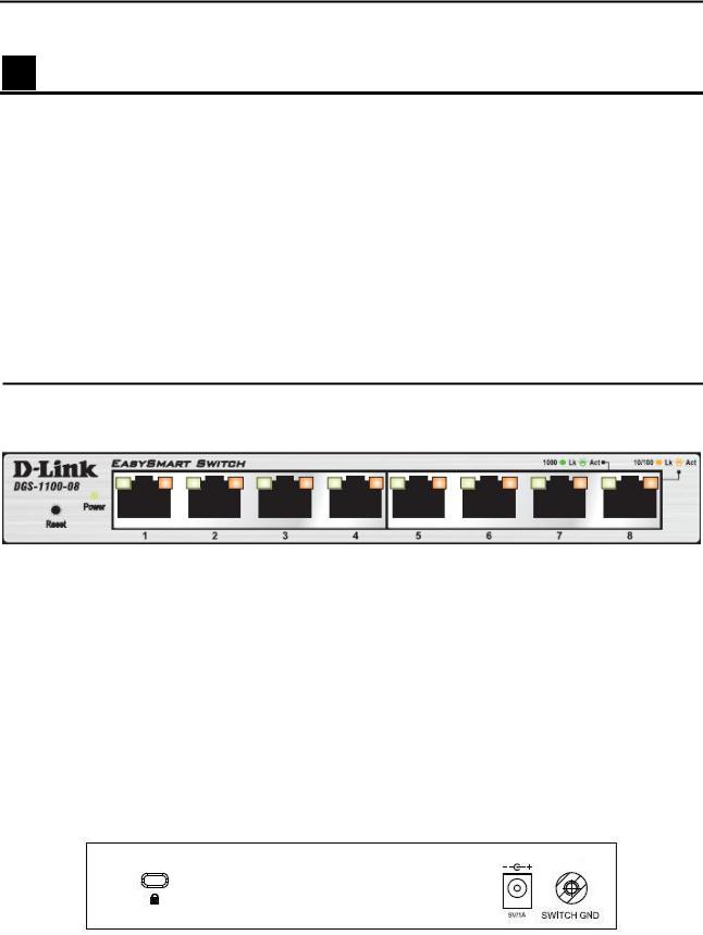
Figure 1 – DGS-1100-08 Front Panel
Power LED: The Power LED lights up when the Switch is connected to a power source.
Link/Act/Speed LED (Ports 1-8):
Flashing: Indicates a network link through the corresponding port.
Blinking: Indicates that the Switch is either sending or receiving data to the port. Green: Indicates that the port is running at 1000M.
Amber: Indicates that the port is running at 10/100M. Light off: No link.
Reset: By pressing the Reset button for 5 seconds the Switch will change back to the default configuration and all changes will be lost.
Rear Panel
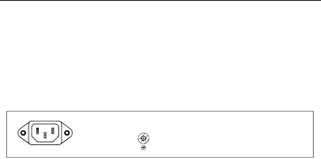
Figure 2 – DGS-1100-08 Rear Panel
5V/1A AC adapter: The port is where to connect the 5V/1A AC adapter.
2

D-Link EasySmart Switch User Manual
DGS-1100-16
16-Port 10/100/1000Mpbs EasySmart Switch
Front Panel
Figure 3 - DGS-1100-16 Front Panel
Power LED: The Power LED lights up when the Switch is connected to a power source.
Link/Act/Speed LED (Ports 1-16):
Flashing: Indicates a network link through the corresponding port.
Blinking: Indicates that the Switch is either sending or receiving data to the port. Green: Indicates that the port is running at 1000M.
Amber: Indicates that the port is running at 10/100M. Light off: No link.
Reset: By pressing the Reset button for 5 seconds the Switch will change back to the default configuration and all changes will be lost.
Rear Panel
Figure 4– DGS-1100-16 Rear Panel
Power: The power port is where to connect the AC power cord.
DGS-1100-24
24-Port 10/100/1000Mpbs EasySmart Switch
Front Panel
Figure 5 – DGS-1100-24 Front Panel
Power LED: The Power LED lights up when the Switch is connected to a power source.
Link/Act/Speed LED (Ports 1-24):
Flashing: Indicates a network link through the corresponding port.
3
D-Link EasySmart Switch User Manual
Blinking: Indicates that the Switch is either sending or receiving data to the port.
Green: Indicates that the port is running at 1000M.
Amber: Indicates that the port is running at 10/100M.
Light off: No link.
Reset: Press the reset button for 5 seconds to reset the Switch back to the default settings. All previous changes will be lost.
Rear Panel
Figure 6– DGS-1100-24 Rear Panel
Power: Connect the supplied AC power cable to this port.
4
D-Link EasySmart Switch User Manual
2 Hardware Installation
This chapter provides unpacking and installation information for the D-Link EasySmart Switch.
Step 1: Unpacking
Open the shipping carton and carefully unpack its contents. Please consult the packing list located in the User Manual to make sure all items are present and undamaged. If any item is missing or damaged, please contact your local D-Link reseller for replacement.
Packing contents of DGS-1100-08
One D-Link EasySmart Switch
One AC Power Adapter
Four rubber feet
One accessory kit for wall-mount installation
One ground screw that screw on the D-Link EasySmart Switch
One Multi-lingual Getting Started Guide
One CD with User Manual and SmartConsole Utility program
Packing contents of DGS-1100-16/24
One D-Link EasySmart Switch
One AC power cord
Four rubber feet
Screws and two mounting brackets
One accessory kit for a ground screw
One Multi-lingual Getting Started Guide
One CD with User Manual and SmartConsole Utility program
If any item is found missing or damaged, please contact the local reseller for replacement.
Step 2: Switch Installation
For safe switch installation and operation, it is recommended that you:
Visually inspect the power cord to see that it is secured fully to the AC power connector. Make sure that there is proper heat dissipation and adequate ventilation around the switch. Do not place heavy objects on the switch.
Desktop or Shelf Installation
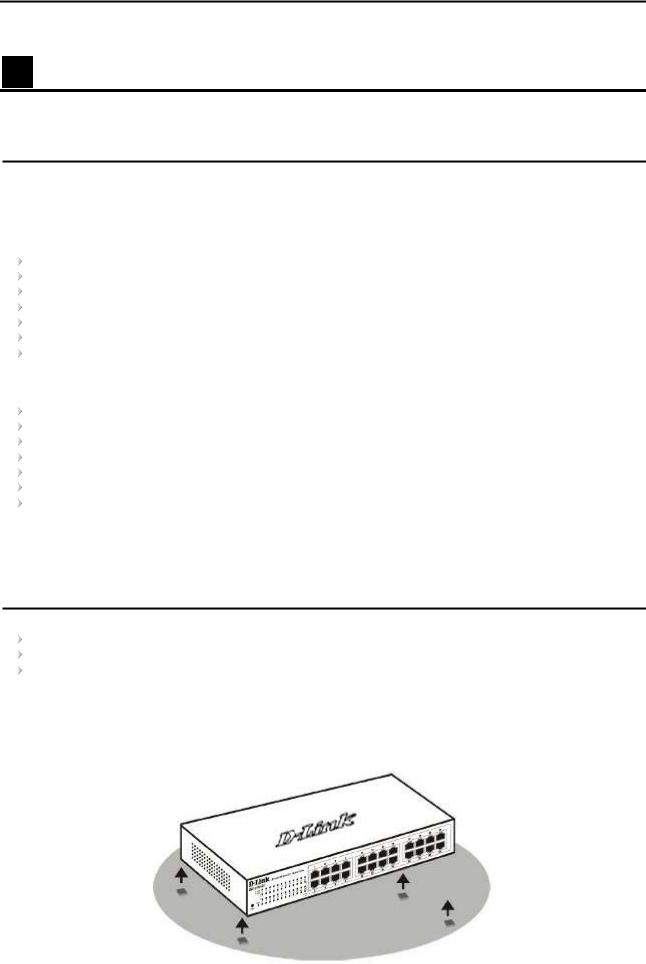
When installing the switch on a desktop or shelf, the rubber feet included with the device must be attached on the bottom at each corner of the device’s base. Allow enough ventilation space between the device and the objects around it.
Figure 7 – Attach the adhesive rubber pads to the bottom
5
D-Link EasySmart Switch User Manual
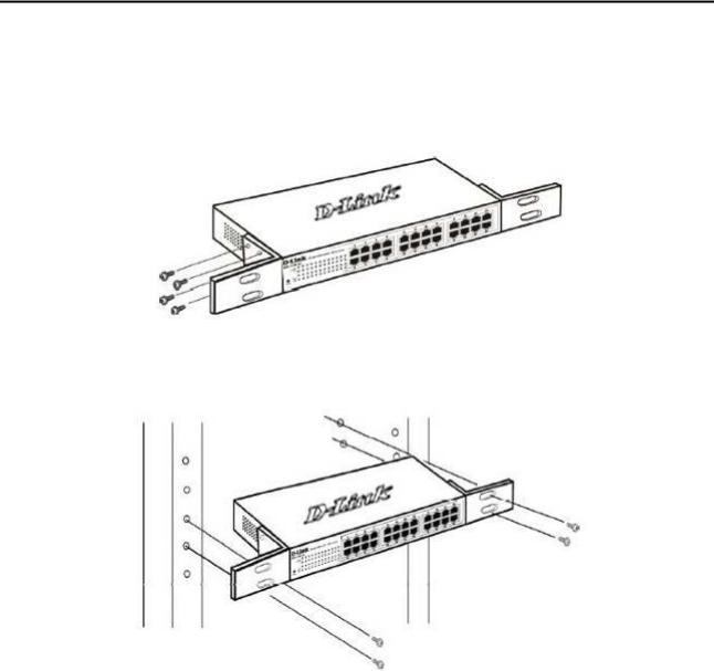
Rack Installation
The switch can be mounted in an EIA standard size 11-inch rack, which can be placed in a wiring closet with other equipment. To install, attach the mounting brackets to the switch’s side panels (one on each side) and secure them with the screws provided (please note that these brackets are not designed for palm size switches).
Figure 8 – Attach the mounting brackets to the Switch
Then, use the screws provided with the equipment rack to mount the switch in the rack.
Figure 9– Mount the Switch in the rack or chassis
Please be aware of following safety Instructions when installing:
A)Elevated Operating Ambient - If installed in a closed or multi-unit rack assembly, the operating ambient temperature of the rack environment may be greater than room ambient. Therefore, consideration should be given to installing the equipment in an environment compatible with the maximum ambient temperature (Tma) specified by the manufacturer.
B)Reduced Air Flow - Installation of the equipment in a rack should be such that the amount of air flow required for safe operation of the equipment is not compromised.
C)Mechanical Loading - Mounting of the equipment in the rack should be such that a hazardous condition is not achieved due to uneven mechanical loading.
D)Circuit Overloading - Consideration should be given to the connection of the equipment to the supply circuit and the effect that overloading of the circuits might have on overcurrent protection and supply wiring. Appropriate consideration of equipment nameplate ratings should be used when addressing this concern.
E)Reliable Earthing - Reliable earthing of rack-mounted equipment should be maintained. Particular attention should be given to supply connections other than direct connections to the branch circuit (e.g. use of power strips)."
6
D-Link EasySmart Switch User Manual
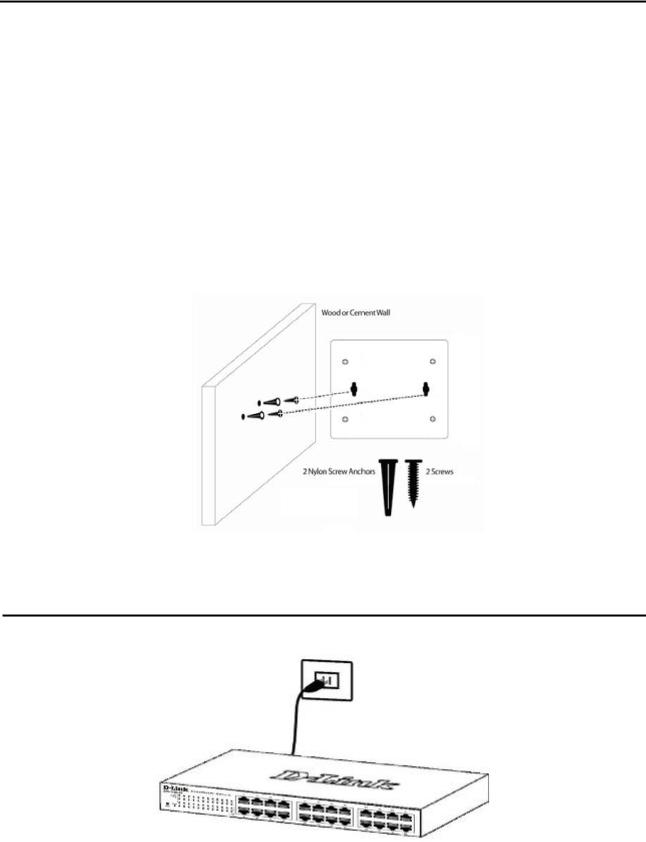
Wall-mount
The Switch can be mounted on a wall. Two mounting slots are provided on the bottom of the switch for this purpose.
Please follow the installation steps to complete wall-mount process.
Mounting on a cement wall
Step 1: Mount the nylon screw anchors ø5 x 22L mm (included in the accessory kit ) into a cement wall Step 2: Drive the T3 x 15L screws into the nylon screw anchors.
Step 3: Hook the mounting holes of the switch back on the screws.
Mounting on a wood wall
Step 1: Drive the T3 x 15L screws into a wood wall.
Step 2. Hook the mounting holes of the switch back on the screws.
Figure 10 –Wall mount installation
Step 3 – Plugging in the AC Power Cord
Users may now connect the AC power cord into the rear of the switch and to an electrical outlet (preferably one that is grounded and surge protected).
Figure 11 –Plugging the switch into an outlet
Power Failure
As a precaution, the switch should be unplugged in case of power failure. When power is resumed, plug the switch back in.
7
D-Link EasySmart Switch User Manual
Grounding the Switch
This section describes how to connect the EasySmart Switch to ground. You must complete this procedure before powering your switch.
Required Tools and Equipment
Ground screws (included in the accessory kit): One M4 x 6 mm (metric) pan-head screw
Ground cable (not included in the accessory kit): The grounding cable should be sized according to local and national installation requirements. Depending on the power supply and system, a 12 to 6 AWG copper conductor is required for U.S installation. Commercially available 6 AWG wire is recommended. The length of the cable depends on the proximity of the switch to proper grounding facilities.
A screwdriver (not included in the accessory kit)
The following steps let you connect the switch to a protective ground: Step 1: Verify if the system power is off.
Step 2: Use the ground cable to place the #8 terminal lug ring on top of the ground-screw opening, as seen in the figure below.
Step 3: Insert the ground screw into the ground-screw opening.
Step 4: Using a screwdriver, tighten the ground screw to secure the ground cable to the switch.
Step 5: Attach the terminal lug ring at the other end of the grounding cable to an appropriate grounding stud or bolt on rack where the switch is installed.
Step 6: Verify if the connections at the ground connector on the switch and the rack are securely attached.
Figure 12 –Ground cable, screw and #8 terminal lug ring
8

D-Link EasySmart Switch User Manual
3 Getting Started
This chapter introduces the management interface of D-Link EasySmart Switch.
Management Options
The D-Link EasySmart Switch can be managed through any port on the device by using the Web-based Management or through any PC using the SmartConsole Utility.
Each switch must be assigned its own IP Address, which is used for communication with Web-Based Management. The PC’s IP address should be in the same range as the switch. Each switch can allow only one user to access the Web-Based Management at a time.
The PC should have an IP address in the same range as the switch. Each switch can allow one user to access to the Web-Based Management at a time.
However, if you want to manage multiple D-Link EasySmart Switches, the SmartConsole Utility is a more convenient choice. By using the SmartConsole Utility, you do not need to change the IP address of your PC and it is easier to initialize multiple EasySmart Switches.
Please refer to the following installation instructions for the Web-based Management and the SmartConsole Utility.
Using Web-based Management
After a successful physical installation, you can configure the Switch, monitor the network status, and display statistics using a web browser.
Supported Web Browsers
The embedded Web-based Management currently supports the following web browsers:
Internet Explorer 6 or later version
Netscape 8 or later version
Firefox 3.0 or later version
Chrome 5.0 or later version
Safari 4.0 or later version Opera 10 or later version
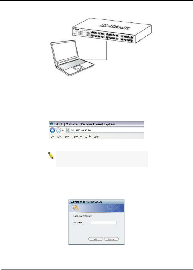
Connecting to the Switch
You will need the following equipment to begin the web configuration of your device:
1.A PC with a RJ-45 Ethernet connection
2.A standard Ethernet cable
Connect the Ethernet cable to any of the ports on the front panel of the switch and to the Ethernet port on the PC.
9
D-Link EasySmart Switch User Manual
Figure 13 –Connected Ethernet cable
Login Web-based Management
In order to login and configure the switch via an Ethernet connection, the PC must have an IP address in the same subnet as the switch. For example, if the switch has an IP address of 10.90.90.90, the PC should have an IP address of 10.x.y.z (where x/y is a number between 0 ~ 254 and z is a number between 1 ~ 254), and a subnet mask of 255.0.0.0. There are two ways to launch the Web-based Management, you may either click the Web Access button at the top of the SmartConsole Utility or open the web browser and enter 10.90.90.90 (the factory-default IP address) in the address bar. Then press <Enter>.
Figure 14 –Enter the IP address 10.90.90.90 in the web browser
NOTE: The switch's factory default IP address is 10.90.90.90 with a subnet mask of 255.0.0.0 and a default gateway of 0.0.0.0.
The web configuration can also be accessed through the SmartConsole Utility. Open the SmartConsole Utility and double-click the switch as it appears in the Monitor List. This will automatically load the web configuration in your web browser.
When the following logon dialog box appears, enter the password then click OK. The default password is admin.
Figure 15 – Logon Dialog Box
SmartConsole Utility
The SmartConsole Utility included in the installation CD is a program for discovering D-Link Smart Switches and EasySmart Switches within the same L2 network segment connected to your PC. This tool is only for computers running Windows 2000, Windows XP, Windows Vista x64/32 or Windows 7 x64/32 operating systems. There are two options for the installation of the SmartConsole Utility; one is through the autorun program on the installation CD and the other is manual installation.
10

D-Link EasySmart Switch User Manual
NOTE: Please be sure to uninstall any existing SmartConsole Utility from your PC before installing the latest SmartConsole Utility.
Option 1: Follow these steps to install the SmartConsole Utility via the autorun program on the installation CD.
1.Insert the Utility CD into your CD-Rom/DVD-Rom Drive.
2.The autorun program will appear automatically.
3.Click on the ”Install SmartConsole Utility” button and an installation wizard will guide you through the process.
4.After successfully installing the SmartConsole Utility, you can open the utility by clicking Start > Programs > D-Link SmartConsole Utility.
5.Connect the Smart Switch to the same L2 network segment of your PC and use the SmartConsole Utility to discover the Smart Switches.
Option 2: Follow these steps to install the SmartConsole Utility manually.
1.Insert the Utility CD into your CD-Rom/DVD-Rom Drive.
2.From the Start menu on the Windows desktop, click Computer.
3.Double click on you CD-Rom/DVD-Rom Drive to start the autorun menu, or right click on the Drive to open the folder. Select SmartConsole Utility and double click on the .exe file.
4.Follow the on-screen instructions to install the utility.
5.Upon completion, go to Start > Programs > D-Link SmartConsole Utility and open the SmartConsole Utility.
6.Connect the Smart Switch to the same L2 network segment of your PC and use the SmartConsole Utility to discover the Smart Switches.
For detailed explanations of SmartConsole’s functions, please refer to Chapter 4 SmartConsole Utility
11
Loading...