


 Loading...
User Manual
Product Model: DES-1210-10/ME, DES-1210-26/ME,
DES-1210-28/ME L2 Managed Metro Ethernet Switch
Release: R6.02
Table of Contents |
DES-1210 Metro Ethernet Managed Switch User Manual |
Table of Contents |
|
Table of Contents ............................................................................................................................................. |
i |
About This Guide............................................................................................................................................. |
1 |
Terms/Usage.................................................................................................................................................. |
1 |
Copyright and Trademarks ............................................................................................................................ |
1 |
1 Product Introduction ................................................................................................................................... |
2 |
Switch Description.......................................................................................................................................... |
2 |
Front Panel Description.................................................................................................................................. |
2 |
LED Indicators................................................................................................................................................ |
4 |
Rear Panel Description .................................................................................................................................. |
5 |
Side Panel Description................................................................................................................................... |
5 |
Gigabit Combo Ports...................................................................................................................................... |
7 |
2 Hardware Installation .................................................................................................................................. |
8 |
Step 1: Unpacking.......................................................................................................................................... |
8 |
Step 2: Switch Installation .............................................................................................................................. |
8 |
Desktop or Shelf Installation....................................................................................................................... |
8 |
Rack Installation ......................................................................................................................................... |
8 |
Step 3 – Plugging in the AC Power Cord....................................................................................................... |
9 |
Power Failure ........................................................................................................................................... |
10 |
3 Getting Started........................................................................................................................................... |
11 |
Management Options................................................................................................................................... |
11 |
Using Web-based Management .................................................................................................................. |
11 |
Supported Web Browsers ........................................................................................................................ |
11 |
Connecting to the Switch.......................................................................................................................... |
11 |
Login Web-based Management ............................................................................................................... |
11 |
Web-based Management............................................................................................................................. |
12 |
4 Configuration ............................................................................................................................................. |
13 |
Web-based Management............................................................................................................................. |
13 |
Tool Bar > Save Menu ................................................................................................................................. |
14 |
Save Configuration ................................................................................................................................... |
14 |
Save Log .................................................................................................................................................. |
14 |
Tool Bar > Tool Menu .................................................................................................................................. |
14 |
Reset System ........................................................................................................................................... |
14 |
Reboot Device .......................................................................................................................................... |
14 |
Configuration Backup & Restore .............................................................................................................. |
15 |
Firmware Backup & Upgrade ................................................................................................................... |
15 |
Tool Bar > Online Help................................................................................................................................. |
16 |
Function Tree ............................................................................................................................................... |
16 |
Device Information.................................................................................................................................... |
17 |
System > System Settings ....................................................................................................................... |
18 |
System > Serial Port Settings................................................................................................................... |
18 |
System > IPv6 System Settings ............................................................................................................... |
19 |
System > IPv6 Route Settings.................................................................................................................. |
19 |
System > IPv6 Neighbor Settings ............................................................................................................ |
20 |
System > DHCP Auto Configuration ........................................................................................................ |
20 |
System > Trap Settings ............................................................................................................................ |
20 |
System > Port Configuration > Port Settings ........................................................................................... |
21 |
System > Port Configuration > Port Description ...................................................................................... |
22 |
i

Table of Contents |
DES-1210 Metro Ethernet Managed Switch User Manual |
|
System > Port Configuration > Port Error Disabled ................................................................................. |
|
22 |
System > SNMP Settings > SNMP Global State ..................................................................................... |
|
23 |
System > SNMP Settings > SNMP User Table........................................................................................ |
|
23 |
System > SNMP Settings > SNMP Group Table ..................................................................................... |
|
24 |
System > SNMP Settings > SNMP View Table ....................................................................................... |
|
24 |
System > SNMP Settings > SNMP Community Table |
............................................................................. |
25 |
System > SNMP Settings > SNMP Host Table ........................................................................................ |
|
25 |
System > SNMP Settings > SNMP Engine ID ......................................................................................... |
|
25 |
System > SNMP Settings > SNMP Trap Settings .................................................................................... |
|
26 |
System > User Accounts .......................................................................................................................... |
|
26 |
System > MAC Address Aging Time........................................................................................................ |
|
26 |
System > ARP Aging Time Settings......................................................................................................... |
|
27 |
System > PPPoE Circuit ID Insertion Settings ......................................................................................... |
|
27 |
System > Web Settings ............................................................................................................................ |
|
28 |
System > Telnet Settings ......................................................................................................................... |
|
28 |
System > Password Encryption................................................................................................................ |
|
28 |
System > Ping Test .................................................................................................................................. |
|
28 |
System > MAC Notification Settings ........................................................................................................ |
|
29 |
System > System Log Configuration > System Log Settings .................................................................. |
29 |
|
System > System Log Configuration > System Log Server ..................................................................... |
29 |
|
System > SMTP Service > SMTP Server Settings .................................................................................. |
|
30 |
System > SMTP Service > SMTP Service ............................................................................................... |
|
31 |
Configuration > 802.1Q VLAN.................................................................................................................. |
|
31 |
Configuration > 802.1Q Management VLAN............................................................................................ |
|
33 |
Configuration > VLAN Status ................................................................................................................... |
|
33 |
Configuration > GVRP Settings................................................................................................................ |
|
33 |
Configuration > GVRP Timer Settings ..................................................................................................... |
|
34 |
Configuration > QinQ > QinQ Settings ..................................................................................................... |
|
35 |
Configuration > QinQ > VLAN Translation CVID Entry Settings .............................................................. |
35 |
|
Configuration > 802.1v Protocol VLAN > 802.1v Protocol Group Settings .............................................. |
36 |
|
Configuration > 802.1v Protocol VLAN > 802.1v Protocol VLAN Settings............................................... |
37 |
|
Configuration > VLAN Trunk Settings ...................................................................................................... |
|
37 |
Configuration > Link Aggregation > Port Trunkings ................................................................................. |
|
37 |
Configuration > Link Aggregation > LACP Port Settings.......................................................................... |
38 |
|
Configuration > BPDU Protection Settings............................................................................................... |
|
39 |
Configuration > IGMP Snooping > IGMP Snooping ................................................................................. |
|
39 |
Configuration > IGMP Snooping > IGMP Access Control Settings.......................................................... |
41 |
|
Configuration > IGMP Snooping > ISM VLAN Settings ........................................................................... |
41 |
|
Configuration > IGMP Snooping > Host Table ......................................................................................... |
|
43 |
Configuration > IGMP Snooping > IP Multicast Profile Settings .............................................................. |
43 |
|
Configuration > IGMP Snooping > Limited Multicast Range Settings...................................................... |
43 |
|
Configuration > IGMP Snooping > Max Multicast Group Settings ........................................................... |
43 |
|
Configuration > MLD Snooping > MLD Snooping Settings ...................................................................... |
44 |
|
Configuration > MLD Snooping > MLD Host Table.................................................................................. |
|
45 |
Configuration > Port Mirroring .................................................................................................................. |
|
45 |
Configuration > Loopback Detection ........................................................................................................ |
|
46 |
Configuration > SNTP Settings > Time Settings ...................................................................................... |
|
46 |
Configuration > SNTP Settings > TimeZone Settings .............................................................................. |
|
47 |
Configuration > DHCP/BOOTP Relay > DHCP/BOOTP Relay Global Settings ...................................... |
47 |
|
ii |
|
|

Table of Contents |
DES-1210 Metro Ethernet Managed Switch User Manual |
|
Configuration > DHCP/BOOTP Relay > DHCP/BOOTP Relay Interface Settings .................................. |
49 |
|
Configuration > DHCP Local Relay Settings............................................................................................ |
|
49 |
Configuration > DHCPv6 Relay Settings.................................................................................................. |
|
50 |
Configuration > Firmware Information...................................................................................................... |
|
50 |
Configuration > Spanning Tree > STP Bridge Global Settings ................................................................ |
51 |
|
Configuration > Spanning Tree > STP Port Settings ............................................................................... |
|
52 |
Configuration > Spanning Tree > MST Configuration Identification......................................................... |
53 |
|
Configuration > Spanning Tree > STP Instance Settings ........................................................................ |
54 |
|
Configuration > Spanning Tree > MSTP Port Information ....................................................................... |
55 |
|
Configuration > Ethernet OAM > Ethernet OAM Port Settings ................................................................ |
55 |
|
Configuration > Ethernet OAM > Ethernet OAM Event Configuration ..................................................... |
56 |
|
Configuration > DULD > DULD Port Settings .......................................................................................... |
|
56 |
Configuration > Multicast Forwarding & Filtering > Multicast Forwarding ................................................ |
57 |
|
Configuration > Multicast Forwarding & Filtering > Multicast Filtering ..................................................... |
57 |
|
QoS > Traffic Control................................................................................................................................ |
|
58 |
QoS > Bandwidth Control......................................................................................................................... |
|
59 |
QoS > CoS Scheduling Mechanism ......................................................................................................... |
|
60 |
QoS > CoS Output Scheduling ................................................................................................................ |
|
60 |
QoS > 802.1p Default Priority................................................................................................................... |
|
60 |
QoS > 802.1p User Priority ...................................................................................................................... |
|
61 |
QoS > DSCP Priority Settings .................................................................................................................. |
|
61 |
QoS > Priority Settings ............................................................................................................................. |
|
62 |
QoS > MAC Priority Settings .................................................................................................................... |
|
62 |
QoS > IP Priority Settings......................................................................................................................... |
|
62 |
QoS > IPv6 Priority Settings..................................................................................................................... |
|
63 |
QoS > IPv6 Traffic Class Priority Settings................................................................................................ |
|
63 |
QoS > TCP/UDP Port Priority Settings .................................................................................................... |
|
63 |
QoS > VLAN ID Priority Settings .............................................................................................................. |
|
64 |
QoS > Protocol Priority Settings............................................................................................................... |
|
64 |
RMON > RMON Basic Settings................................................................................................................ |
|
64 |
RMON > RMON Ethernet Statistics Configuration................................................................................... |
|
64 |
RMON > RMON History Control Configuration ........................................................................................ |
|
65 |
RMON > RMON Alarm Configuration ...................................................................................................... |
|
65 |
RMON > RMON Event Configuration....................................................................................................... |
|
66 |
Security > Trusted Host............................................................................................................................ |
|
66 |
Security > Safeguard Engine.................................................................................................................... |
|
67 |
Security > ARP Spoofing Prevention ....................................................................................................... |
|
67 |
Security > Gratuitous ARP ....................................................................................................................... |
|
68 |
Security > Port Security............................................................................................................................ |
|
68 |
Security > SSL Settings............................................................................................................................ |
|
69 |
Security > Smart Binding > Smart Binding Settings ................................................................................. |
|
70 |
Security > Smart Binding > Smart Binding ............................................................................................... |
|
71 |
Security > Smart Binding > White List...................................................................................................... |
|
72 |
Security > Smart Binding > Black List ...................................................................................................... |
|
72 |
Security > Smart Binding > DHCP Snooping List .................................................................................... |
|
73 |
Security > 802.1X > 802.1X Settings ....................................................................................................... |
|
73 |
Security > 802.1X > 802.1X User............................................................................................................. |
|
74 |
Security > 802.1X > 802.1X Authentication RADIUS ............................................................................... |
|
74 |
Security > 802.1X > 802.1X Guest VLAN ................................................................................................ |
|
75 |
iii |
|
|

Table of Contents |
DES-1210 Metro Ethernet Managed Switch User Manual |
|
Security > MAC Address Table > Static MAC .......................................................................................... |
|
75 |
Security > MAC Address Table > Dynamic Forwarding Table................................................................. |
77 |
|
Security > Access Authentication Control > Authentication Policy Settings ............................................ |
77 |
|
Security > Access Authentication Control > Application Authentication Settings .................................... |
78 |
|
Security > Access Authentication Control > Authentication Server Group .............................................. |
78 |
|
Security > Access Authentication Control > Authentication Server ......................................................... |
79 |
|
Security > Access Authentication Control > Login Method Lists.............................................................. |
80 |
|
Security > Access Authentication Control > Enable Method Lists ........................................................... |
81 |
|
Security > Access Authentication Control > Local Enable Password Settings ........................................ |
81 |
|
Security > Traffic Segmentation ............................................................................................................... |
|
82 |
Security > DoS Prevention Settings ......................................................................................................... |
|
82 |
Security > DHCP Server Screening > DHCP Server Screening Port Settings ........................................ |
83 |
|
Security > DHCP Server Screening > Filter DHCP Server ...................................................................... |
83 |
|
Security > SSH Settings > SSH Settings ................................................................................................. |
|
83 |
Security > SSH Settings > SSH Authmode and Algorithm Settings ........................................................ |
84 |
|
Security > SSH Settings > SSH User Authentication Lists ...................................................................... |
85 |
|
Monitoring > Statistics .............................................................................................................................. |
|
85 |
Monitoring > Session Table...................................................................................................................... |
|
86 |
Monitoring > CPU Utilization .................................................................................................................... |
|
87 |
Monitoring > Memory Utilization ............................................................................................................... |
|
87 |
Monitoring > Port Utilization ..................................................................................................................... |
|
88 |
Monitoring > Packet Size.......................................................................................................................... |
|
88 |
Monitoring > Packets > Transmitted (TX) ................................................................................................ |
|
90 |
Monitoring > Packets > Received (RX) .................................................................................................... |
|
91 |
Monitoring > Packets > UMB Cast (RX)................................................................................................... |
|
93 |
Monitoring > Errors > Received (RX) ....................................................................................................... |
|
94 |
Monitoring > Errors > Transmitted (TX).................................................................................................... |
|
95 |
Monitoring > Cable Diagnostics ............................................................................................................... |
|
97 |
Monitoring > System Log.......................................................................................................................... |
|
98 |
Monitoring > Browse ARP Table .............................................................................................................. |
|
98 |
Monitoring > Ethernet OAM > Browse Ethernet OAM Event Log ............................................................ |
98 |
|
Monitoring > Ethernet OAM > Browse Ethernet OAM Statistics .............................................................. |
99 |
|
Monitoring > Port Access Control > RADIUS Authentication ................................................................... |
99 |
|
Monitoring > Port Access Control > RADIUS Account Client ................................................................ |
101 |
|
ACL > ACL Configuration Wizard........................................................................................................... |
|
102 |
ACL > Access Profile List ....................................................................................................................... |
|
103 |
ACL > ACL Finder .................................................................................................................................. |
|
104 |
ACL > CPU Filter Configuration Wizard ................................................................................................. |
|
104 |
ACL > CPU Filter Access Profile List ..................................................................................................... |
|
105 |
ACL > CPU Filter Finder......................................................................................................................... |
|
106 |
LLDP > LLDP Global Settings ................................................................................................................ |
|
106 |
LLDP > Basic LLDP Port Settings .......................................................................................................... |
|
107 |
LLDP > 802.1 Extension LLDP Port Settings......................................................................................... |
|
108 |
LLDP > 802.3 Extension LLDP Port Settings......................................................................................... |
|
108 |
LLDP > LLDP Management Address Settings ....................................................................................... |
|
109 |
LLDP > LLDP Statistics Table ................................................................................................................ |
|
110 |
LLDP > LLDP Management Address Table ........................................................................................... |
|
110 |
LLDP > LLDP Local Port Table .............................................................................................................. |
|
111 |
LLDP > LLDP Remote Port Table .......................................................................................................... |
|
112 |
|
iv |
|

Table of Contents |
DES-1210 Metro Ethernet Managed Switch User Manual |
Appendix A - Ethernet Technology............................................................................................................ |
114 |
Gigabit Ethernet Technology ..................................................................................................................... |
114 |
Fast Ethernet Technology .......................................................................................................................... |
114 |
Switching Technology ................................................................................................................................ |
114 |
Appendix B - Ethernet Technology............................................................................................................ |
115 |
Hardware Specifications ............................................................................................................................ |
115 |
Features ..................................................................................................................................................... |
117 |
L2 Features ............................................................................................................................................ |
117 |
VLAN ...................................................................................................................................................... |
117 |
L3 Features ............................................................................................................................................ |
117 |
QoS (Quality of Service)......................................................................................................................... |
117 |
Security................................................................................................................................................... |
117 |
OAM ....................................................................................................................................................... |
118 |
Management........................................................................................................................................... |
118 |
Appendix C – Rack mount Instructions .................................................................................................... |
119 |
Appendix D – Cables and Connectors ...................................................................................................... |
120 |
Appendix E– Module Specs and Cable Lengths ...................................................................................... |
122 |
v
About This Guide |
DES-1210 Metro Ethernet Managed Switch User Manual |
|
|
About This Guide
This guide provides instructions to install the D-Link DES-1210 Metro Ethernet Managed Switch and to configure with HTTP step-by-step.
Note: The model you have purchased may appear slightly different from the illustrations shown in the document. Refer to the Product Instruction and Technical Specification sections for detailed information about your switch, its components, network connections, and technical specifications.
This guide is mainly divided into three parts:
1.Hardware Installation: Step-by-step hardware installation procedures.
2.Getting Started: A startup guide for basic switch installation and settings.
3.Configuration: Information about the function descriptions and configuration settings.
Terms/Usage
In this guide, the term “Switch” (first letter capitalized) refers to DES-1210 Metro Ethernet Managed Switch, and “switch” (first letter lower case) refers to other Ethernet switches. Some technologies refer to terms “switch”, “bridge” and “switching hubs” interchangeably, and both are commonly accepted for Ethernet switches.
A NOTE indicates important information that helps a better use of the device.
A CAUTION indicates potential property damage or personal injury.
Copyright and Trademarks
Information in this document is subjected to change without notice. © 2013 D-Link Corporation. All rights reserved.
Reproduction in any manner whatsoever without the written permission of D-Link Corporation is strictly forbidden.
Trademarks used in this text: D-Link and the D-LINK logo are trademarks of D-Link Corporation; Microsoft and Windows are registered trademarks of Microsoft Corporation.
Other trademarks and trade names may be used in this document to refer to either the entities claiming the marks and names or their products. D-Link Corporation disclaims any proprietary interest in trademarks and trade names other than its own.
1

1 Product Introduction |
DES-1210 Metro Ethernet Managed Switch User Manual |
|
|
1 Product Introduction
Switch Description
Front Panel Description
LED Indicators
Rear Panel Description
Side Panel Description
Gigabit Combo Ports
Switch Description
The DES-1210 Metro Ethernet Managed switch is equipped with Copper ports (10/100Mbps) and SFP ports (100/1000Mbps) that can be used to attach various networking devices to the network like Computers, Notebooks, Print Servers, Network Attached Storage devices, IP Cameras, VoIP PBX devices, and other Switches. The Small Form Factor Portable (SFP) combo ports can be used together with fiber-optical transceivers in order to connect various other networking devices, using a fiber-optic connection, to the network at Gigabit Ethernet speeds over great distances.
This DES-1210 Metro Ethernet Managed switch provides unsurpassed performance, fault tolerance, scalability, robust security, standard-based interoperability and impressive technology to future-proof departmental and enterprise network deployments.
It allows IGMP Snooping and Authentication, QoS, Bandwidth Control, ACL and many security functions. It can be managed by Web UI, or commands via Telnet.
The DES-1210 Metro Ethernet Managed features the following list of switches:
|
Switch |
|
|
Description |
|
|
|
|
|
||
|
|
|
|
|
|
|
|
|
|
8 10/100Mbps Copper Ports, 2 Combo 10/100/1000Mbps Copper / |
|
|
DES-1210-10/ME |
|
|
100/1000Mbps SFP Ports, and One RJ-45 Console Port for out-of-band CLI |
|
|
|
|
|
configuration. |
|
|
|
|
|
|
|
|
|
|
|
24 10/100Mbps Copper Ports, 2 Combo 10/100/1000Mbps Copper / |
|
|
DES-1210-26/ME |
|
|
100/1000Mbps SFP Ports, and One RJ-45 Console Port for out-of-band CLI |
|
|
|
|
|
configuration. |
|
|
|
|
|
|
|
|
|
|
|
24 10/100Mbps Copper Ports, 2 100/1000Mbps SFP Ports, 2 Combo |
|
|
DES-1210-28/ME |
|
|
10/100/1000Mbps Copper / 100/1000Mbps SFP Ports, and One RJ-45 Console |
|
|
|
|
|
Port for out-of-band CLI configuration. |
|
|
|
|
|
|
|
These switches have a combination of 1000BASE-T ports and SFP ports that may be used in to uplink various network devices to the Switch, including PCs, hubs and other switches to provide a gigabit Ethernet uplink in full-duplex mode. The SFP (Small Form Factor Portable) combo ports are used with fiber-optical transceiver cabling in order to uplink various other networking devices for a gigabit link that may span great distances.
Front Panel Description
The front panel of the DES-1210-10/ME switch consists out of the following:
8 10/100Mbps Copper Ports
2 Combo 10/100/1000Mbps Copper / 100/1000Mbps SFP port
One RJ-45 Console Port
LEDs for Power, Console, Link/Act for port 1 to 8, and Link/Act/Speed for port 9 and 10
2
1 Product Introduction |
DES-1210 Metro Ethernet Managed Switch User Manual |
|
|
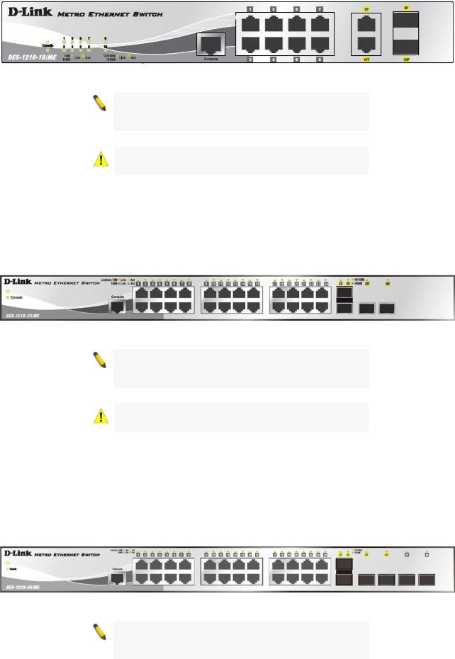
Figure 1.1 – DES-1210-10/ME Front Panel
NOTE: The MiniGBIC ports are shared with normal RJ-45 ports 9 and 10. When MiniGBIC port is used, the RJ-45 port cannot be used.
CAUTION: The MiniGBIC ports should use UL listed
Optical Transceiver product, Rated Laser Class I. 3.3Vdc.
The front panel of the DES-1210-26/ME switch consists out of the following:
24 10/100Mbps Copper Ports
2 Combo 10/100/1000Mbps Copper / 100/1000Mbps SFP port
One RJ-45 Console Port
LEDs for Power, Console, Link/Act for port 1 to 24, and Link/Act/Speed for port 25 and 26
Figure 1.2 – DES-1210-26/ME Front Panel
NOTE: The MiniGBIC ports are shared with normal RJ-45 ports 25 and 26. When MiniGBIC port is used, the RJ-45 port cannot be used.
CAUTION: The MiniGBIC ports should use UL listed
Optical Transceiver product, Rated Laser Class I. 3.3Vdc.
The front panel of the DES-1210-28/ME switch consists out of the following:
24 10/100Mbps Copper Ports
2 Combo 10/100/1000Mbps Copper / 100/1000Mbps SFP port
2 100/1000Mbps SFP Ports
One RJ-45 Console Port
LEDs for Power, Console, Link/Act for port 1 to 24, and Link/Act/Speed for port 25 and 26
Figure 1.3 – DES-1210-28/ME Front Panel
NOTE: The MiniGBIC ports are shared with normal RJ-45 ports 25 and 26. When MiniGBIC port is used, the RJ-45 port cannot be used.
3
1 Product Introduction |
DES-1210 Metro Ethernet Managed Switch User Manual |
|
|
CAUTION: The MiniGBIC ports should use UL listed
Optical Transceiver product, Rated Laser Class I. 3.3Vdc.
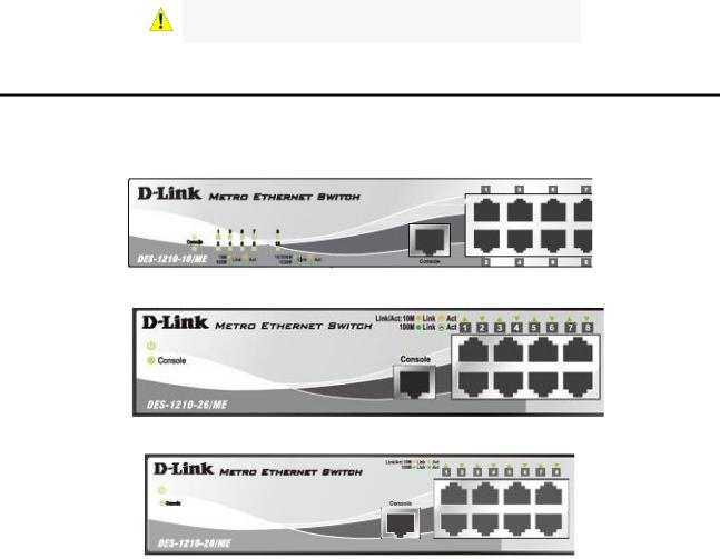
LED Indicators
The Switch supports LED indicators for Power, Console, Fan, and Link/Act or Link/Act/Speed for each port. The following shows the LED indicators for the DES-1210 Metro Ethernet Managed Switch along with an explanation of each indicator.
Figure 1.4 –LED Indicators on DES-1210-10/ME
Figure 1.5 –LED Indicators on DES-1210-26/ME
Figure 1.6 –LED Indicators on DES-1210-28/ME
Location |
|
LED Indicative |
|
Color |
|
Status |
|
Description |
|
|
|
|
|
|
|||||
|
|
|
|
|
|
|
|
|
|
|
|
Power |
|
Green |
|
Solid Light |
|
Power on. |
|
|
|
|
|
|
|
|
|
||
|
|
|
|
Light off |
|
Power off. |
|
||
|
|
|
|
|
|
|
|
||
|
|
|
|
|
|
|
|
|
|
Per Device |
|
|
|
|
|
Solid Light |
|
Console on. |
|
|
|
Console |
|
|
|
|
|
|
|
|
|
|
Green |
|
Blinking |
|
POST is in progress. |
|
|
|
|
|
|
|
|
|
|
|
|
|
|
|
|
|
|
Light off |
|
Console off. |
|
|
|
|
|
|
|
|
|
|
|
|
|
|
|
|
|
|
|
When there is a secure 10/100Mbps |
|
|
|
|
|
|
|
Solid Green |
|
Ethernet connection (or link) at any |
|
LED Per |
|
|
|
|
|
|
|
of the ports. |
|
|
|
|
|
|
|
|
When there is reception or |
|
|
10/100Mbps |
|
Link/Act |
|
Green |
|
|
|
|
|
|
|
|
|
|
transmission (i.e. Activity—Act) of |
|
|||
Copper Port |
|
|
|
|
|
Blinking Green |
|
|
|
|
|
|
|
|
|
|
|
data occurring at a 10/100Mbps |
|
|
|
|
|
|
|
|
|
Ethernet connected port. |
|
|
|
|
|
|
|
Light off |
|
No link. |
|
|
|
|
|
|
|
Solid Green |
|
When there is a secure 1000Mbps |
|
|
|
|
|
|
|
|
|
Ethernet connection (or link) at any |
|
LED Per |
|
|
|
|
|
|
|
of the ports. |
|
10/100/1000Mbps |
Link/Act/Speed |
|
Green/Amber |
|
Blinking Green |
|
When there is reception or |
|
|
Copper Port |
|
|
|
|
|
|
|
transmission (i.e. Activity—Act) of |
|
|
|
|
|
|
|
|
|
data occurring at a 1000Mbps |
|
|
|
|
|
|
|
|
|
Ethernet connected port. |
|
4
1 Product Introduction |
|
DES-1210 Metro Ethernet Managed Switch User Manual |
||
|
|
|
|
|
|
|
|
|
|
|
|
|
Solid Amber |
When there is a secure 10/100Mbps |
|
|
|
|
Ethernet connection (or link) at any |
|
|
|
|
of the ports. |
|
|
|
Blinking Amber |
When there is reception or |
|
|
|
|
transmission (i.e. Activity—Act) of |
|
|
|
|
data occurring at a 10/100Mbps |
|
|
|
|
Ethernet connected port. |
|
|
|
Light off |
No link. |
|
|
|
Solid Green |
When there is a secure 1000Mbps |
|
|
|
|
Ethernet connection (or link) at any |
|
|
|
|
of the ports. |
|
|
|
Blinking Green |
When there is reception or |
|
|
|
|
transmission (i.e. Activity—Act) of |
|
|
|
|
data occurring at a 1000Mbps |
LED Per |
|
|
|
Ethernet connected port. |
100/1000Mbps |
Link/Act/Speed |
Green/Amber |
Solid Amber |
When there is a secure 100Mbps |
SFP Port |
|
|
|
Ethernet connection (or link) at any |
|
|
|
|
of the ports. |
|
|
|
Blinking Amber |
When there is reception or |
|
|
|
|
transmission (i.e. Activity—Act) of |
|
|
|
|
data occurring at a 100Mbps |
|
|
|
|
Ethernet connected port. |
|
|
|
Light off |
No link. |
Rear Panel Description
The rear panel of the Switch contains an AC power connector. The AC power connector is a standard threepronged connector that supports the power cord. Plug-in the female connector of the provided power cord into this socket, and the male side of the cord into a power outlet. The Switch automatically adjusts its power setting to any supply voltage in the range from 100 to 240 VAC at 50 to 60 Hz. Connect the Kensingtoncompatible security lock, at the rear of the switch, to a secure immovable device(only for DES-1210-10/ME). Insert the lock into the notch and turn the key to secure the lock(only for DES-1210-10/ME).
Figure 1.7 –Rear panel view of the DES-1210-10/ME
Figure 1.8 –Rear panel view of the DES-1210-26/ME
Figure 1.9 –Rear panel view of the DES-1210-28/ME
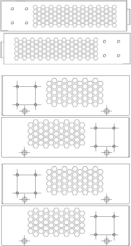
Side Panel Description
The leftand right-hand panels of the Switch have heat vents to dissipate heat. Do not block these openings, and leave at least 6 inches of space at the rear and sides of the Switch for proper ventilation. Be reminded that without proper heat dissipation and air circulation, system components might overheat, which could lead to system failure.
5
1 Product Introduction |
DES-1210 Metro Ethernet Managed Switch User Manual |
|
|
Figure 0-10. Side panels of the DES-1210-10/ME
Figure 0-11. Side panels of the DES-1210-26/M
Figure 0-12. Side panels of the DES-1210-28/ME
6
1 Product Introduction |
DES-1210 Metro Ethernet Managed Switch User Manual |
|
|
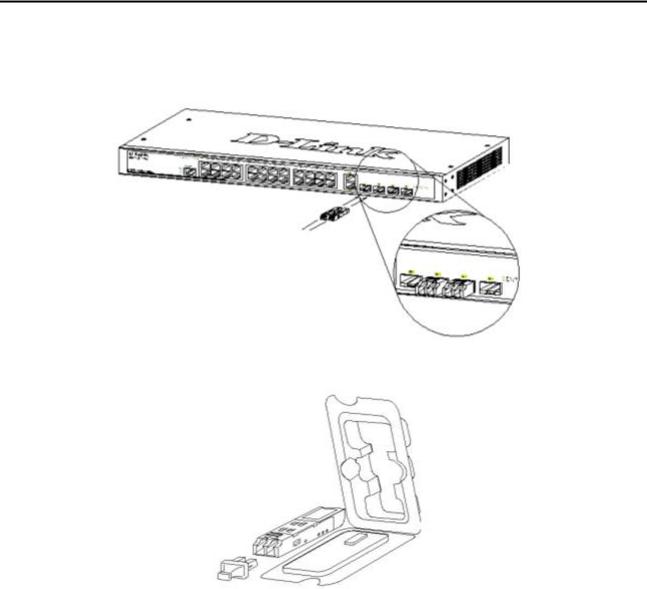
Gigabit Combo Ports
The DES-1210 Series features either two or four Gigabit Ethernet Combo ports. These ports are 1000BASE- T copper ports (optional) and Small Form Factor Portable (SFP) ports (optional). See the diagram below to view the two SFP port modules being plugged into the Switch. Please note that although these two front panel modules can be used simultaneously, the ports must be different. The SFP port will always have the highest priority.
Figure 0-11. Inserting the SFP modules into the Switch
Figure 1-12. Installing the SFP Module
The Switch is equipped with SFP ports, which are to be used with fiber-optical transceiver cabling in order to uplink various other networking devices for a gigabit link that may span great distances. For a full list of supported SFP transceivers, for this switch series, refer to the Appendix-E.
7
2 Hardware Installation |
DES-1210 Metro Ethernet Managed Switch User Manual |
|
|
2 Hardware Installation
This chapter provides unpacking and installation information for the D-Link Metro Ethernet Switch.
Step 1: Unpacking
Open the shipping carton and carefully unpack its contents. Please consult the packing list located in the User Manual to make sure all items are present and undamaged. If any item is missing or damaged, please contact your local D-Link reseller for replacement.
One D-Link Metro Ethernet Switch
One AC power cord
Four rubber feet
Screws and two mounting brackets
One Multi-lingual Getting Started Guide
One CD with User Manual and D-View Module
One RJ-45 cable for console port
If any item is found missing or damaged, please contact the local reseller for replacement.
Step 2: Switch Installation
For safe switch installation and operation, it is recommended that you:
Visually inspect the power cord to see that it is secured fully to the AC power connector. Make sure that there is proper heat dissipation and adequate ventilation around the switch. Do not place heavy objects on the switch.
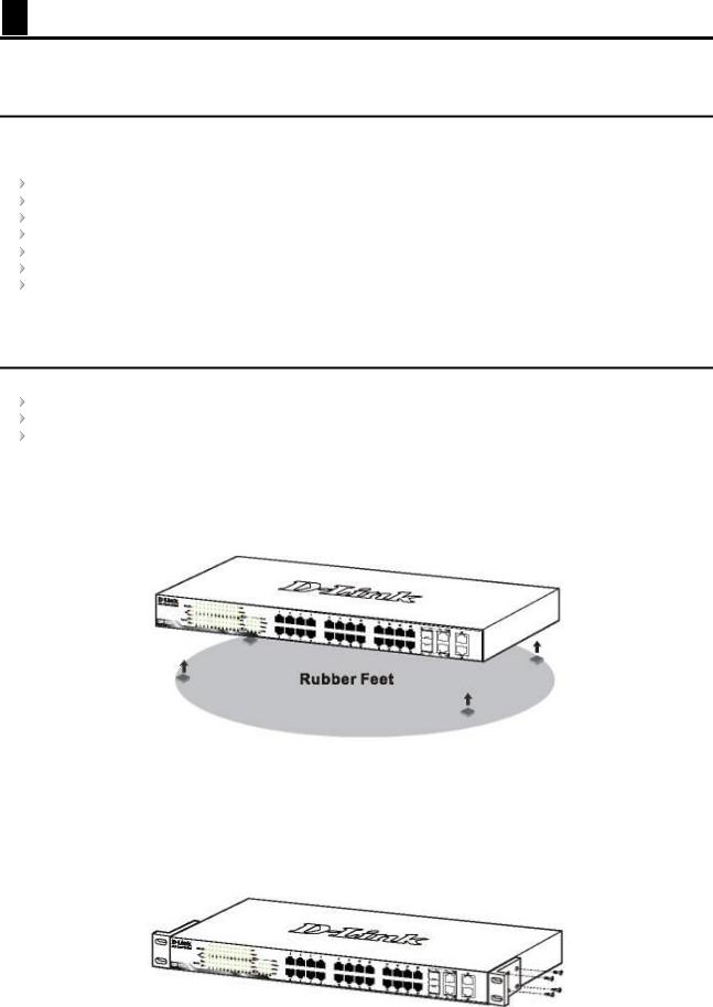
Desktop or Shelf Installation
When installing the switch on a desktop or shelf, the rubber feet included with the device must be attached on the bottom at each corner of the device’s base. Allow enough ventilation space between the device and the objects around it.
Figure 2.1 – Attach the adhesive rubber pads to the bottom
Rack Installation
The switch can be mounted in an EIA standard size 19-inch rack, which can be placed in a wiring closet with other equipment. To install, attach the mounting brackets to the switch’s side panels (one on each side) and secure them with the screws provided (please note that these brackets are not designed for palm size switches).
Figure 2.2 – Attach the mounting brackets to the Switch
8
2 Hardware Installation |
DES-1210 Metro Ethernet Managed Switch User Manual |
|
|
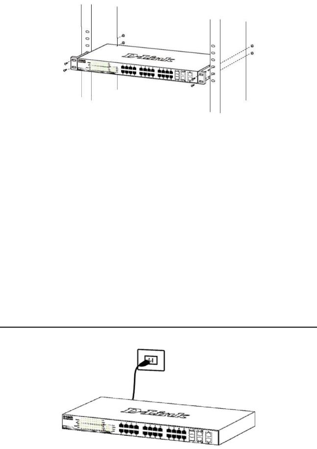
Then, use the screws provided with the equipment rack to mount the switch in the rack.
Figure 2.3 – Mount the Switch in the rack or chassis
Please be aware of following safety Instructions when installing:
A)Elevated Operating Ambient - If installed in a closed or multi-unit rack assembly, the operating ambient temperature of the rack environment may be greater than room ambient. Therefore, consideration should be given to installing the equipment in an environment compatible with the maximum ambient temperature (Tma) specified by the manufacturer.
B)Reduced Air Flow - Installation of the equipment in a rack should be such that the amount of air flow required for safe operation of the equipment is not compromised.
C)Mechanical Loading - Mounting of the equipment in the rack should be such that a hazardous condition is not achieved due to uneven mechanical loading.
D)Circuit Overloading - Consideration should be given to the connection of the equipment to the supply circuit, and the effect that overloading of the circuits might have on overcurrent protection and supply wiring. Appropriate consideration of equipment nameplate ratings should be used when addressing this concern.
E)Reliable Earthing - Reliable earthing of rack-mounted equipment should be maintained. Particular attention should be given to supply connections other than direct connections to the branch circuit (e.g. use of power strips)."
Step 3 – Plugging in the AC Power Cord
Users may now connect the AC power cord into the rear of the switch and to an electrical outlet (preferably one that is grounded and surge protected).
Figure 2.4 – Plugging the switch into an outlet
9
2 Hardware Installation |
DES-1210 Metro Ethernet Managed Switch User Manual |
|
|
Power Failure
As a precaution, the switch should be unplugged in case of power failure. When power is resumed, plug the switch back in.
10
3 Getting Started |
DES-1210 Metro Ethernet Managed Switch User Manual |
|
|
3 Getting Started
This chapter introduces the management interface of D-Link Metro Ethernet Switch.
Management Options
The D-Link Metro Ethernet Switch can be managed through any port on the device by using the Web-based Management.
Each switch must be assigned its own IP Address, which is used for communication with the Web-Based Management or a SNMP network manager. The PC should have an IP address in the same range as the switch. Each switch can allow up to four users to access the Web-Based Management concurrently.
Please refer to the following installation instructions for the Web-based Management.
Using Web-based Management
After a successful physical installation, you can configure the Switch, monitor the network status, and display statistics using a web browser.
Supported Web Browsers
The embedded Web-based Management currently supports the following web browsers:
Internet Explorer 6 or higher
Netscape 8 or higher
Mozilla
Firefox 1.5/2.0 or higher
Connecting to the Switch
You will need the following equipment to begin the web configuration of your device:
1.A PC with a RJ-45 Ethernet connection
2.A standard Ethernet cable
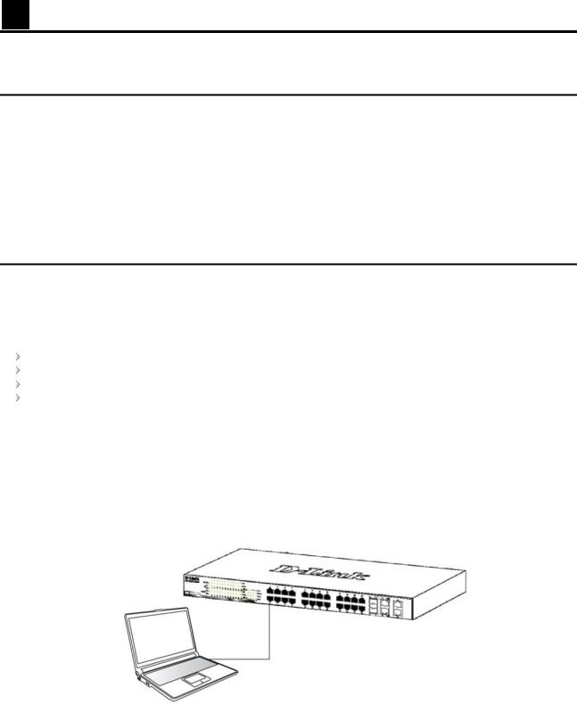
Connect the Ethernet cable to any of the ports on the front panel of the switch and to the Ethernet port on the PC.
Figure 3.1 – Connected Ethernet cable
Login Web-based Management
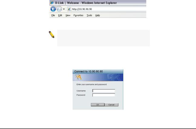
In order to login and configure the switch via an Ethernet connection, the PC must have an IP address in the same subnet as the switch. For example, if the switch has an IP address of 10.90.90.90, the PC should have an IP address of 10.x.y.z (where x/y is a number between 0 ~ 254 and z is a number between 1 ~ 254), and a subnet mask of 255.0.0.0. Enter 10.90.90.90 (the factory default IP address) in the address bar of your web browser and press <Enter>.
11
3 Getting Started |
DES-1210 Metro Ethernet Managed Switch User Manual |
|
|
Figure 3.2 –Enter the IP address 10.90.90.90 in the web browser
NOTE: The switch's factory default IP address is 10.90.90.90 with a subnet mask of 255.0.0.0 and a default gateway of 0.0.0.0.
When the following logon dialog box appears, enter the password and choose the language of the Webbased Management interface then click OK.
By default, the Username and Password are empty.
Figure 3.3 – Logon Dialog Box
Web-based Management
By clicking the OK button in Logon Dialog Box, you will enter the Web-based Management interface. Please refer to Chapter 4 Configuration for detailed instructions.
12
4 Configuration |
DES-1210 Metro Ethernet Managed Switch User Manual |
|
|
4 Configuration
The features and functions of the D-Link Metro Ethernet Managed Switch can be configured for optimum use through the Web-based user interface.
Web-based Management
After press the OK button in Logon Dialog Box, you will see the screen below:
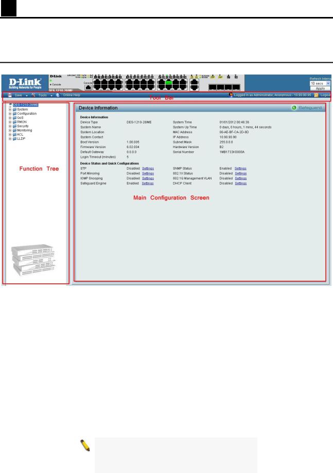
Figure 4.1 – Web-based Management
The above image is the Web-based Management screen. The three main areas are the Tool Bar on top, the
Function Tree, and the Main Configuration Screen.
The Tool Bar provides a quick and convenient way for essential utility functions like firmware and configuration management.
By choosing different functions in the Function Tree, you can change all the settings in the Main Configuration Screen. The main configuration screen will show the current status of your Switch by clicking the model name on top of the function tree.
At the upper right corner of the screen the username and current IP address will be displayed.
Under the username is the Logout button. Click this to end this session.
NOTE: If you close the web browser without clicking the Logout button first, then it will be seen as an abnormal exit and the login session will still be occupied.
13
4 Configuration |
DES-1210 Metro Ethernet Managed Switch User Manual |
|
|
Finally, by clicking on the D-Link logo at the upper-left corner of the screen you will be redirected to the local D-Link website.
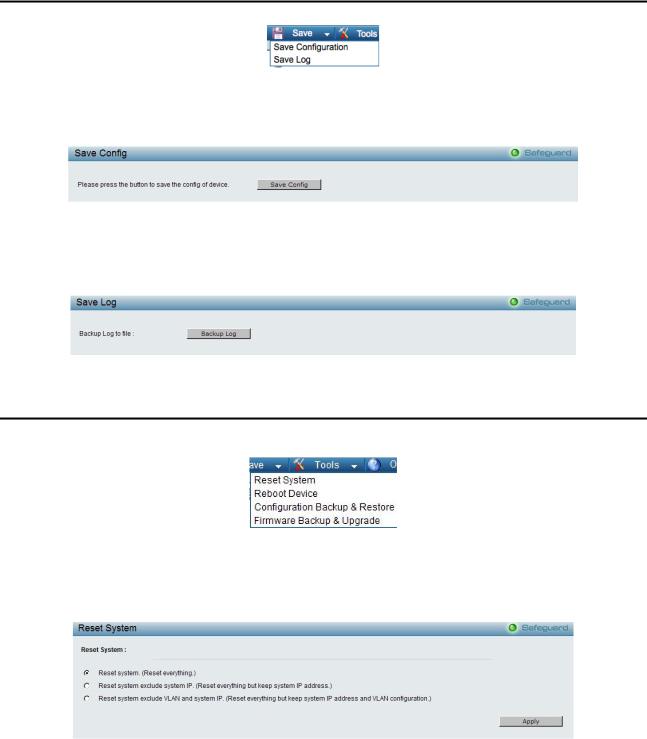
Tool Bar > Save Menu
The Save Menu provides Save Configuration and Save Log functions.
Figure 4.2 – Save Menu
Save Configuration
Select to save the entire configuration changes you have made to the device to switch’s non-volatile RAM.
Figure 4.3 – Save Configuration
Save Log
Save the log entries to your local drive and a pop-up message will prompt you for the file path. You can view or edit the log file by using text editor (e.g. Notepad).
Figure 4.4 – Save Log
Tool Bar > Tool Menu
The Tool Menu offers global function controls such as Reset, Reset System, Reboot Device, Configuration Backup and Restore, Firmware Backup and Upgrade.
Figure 4.5 – Tool Menu
Reset System
Provide another safe reset option for the Switch. All configuration settings in non-volatile RAM will reset to factory default and the Switch will reboot.
Figure 4.6 – Tool Menu > Reset System
Select the different reset method then click Apply to reset the system.
Reboot Device
Provide a safe way to reboot the system. Click Reboot to restart the switch.
14
4 Configuration |
DES-1210 Metro Ethernet Managed Switch User Manual |
|
|
Figure 4.7 – Tool Menu > Reboot Device
Configuration Backup & Restore
Allow the current configuration settings to be saved to a file (not including the password), and if necessary, you can restore configuration settings from this file. Two methods can be selected: HTTP or TFTP.
Figure 4.8 – Tool Menu > Configure Backup and Restore
HTTP: Backup or restore the configuration file to or from your local drive.
Click Backup to save the current settings to your disk.
Click Browse to browse your inventories for a saved backup settings file.
Click Restore after selecting the backup settings file you want to restore.
TFTP: TFTP (Trivial File Transfer Protocol) is a file transfer protocol that allows you to transfer files to a remote TFTP server. Specify TFTP Server IPv4 or IPv6 Address and TFTP File Name for the configuration file you want to save to / restore from. The maximum Telnet Server connection is 4.
Click Backup to save the current settings to the TFTP server.
Click Restore after selecting the backup settings file you want to restore.
Note: Switch will reboot after restore, and all current configurations will be lost.
Firmware Backup & Upgrade
Allow for the firmware to be saved, or for an existing firmware file to be uploaded to the Switch. Two methods can be selected: HTTP or TFTP.
Figure 4.9 – Tool Menu > Firmware Backup and Upgrade
15
4 Configuration |
DES-1210 Metro Ethernet Managed Switch User Manual |
|
|
HTTP: Backup or upgrade the firmware to or from your local PC drive. Click Backup to save the firmware to your disk.
Click Browse to browse your inventories for a saved firmware file. Click Upgrade after selecting the firmware file you want to restore.
TFTP: Backup or upgrade the firmware to or from a remote TFTP server. Specify TFTP Server IPv4 or IPv6 Address and File Name for the configuration file you want to save to / restore from. The maximum Telnet Server connection is 4.
Click Backup to save the firmware to the TFTP server.
Click Upgrade after selecting the firmware file you want to restore.
CAUTION: Do not disconnect the PC or remove the power cord from device until the upgrade completes. The Switch may crash if the Firmware upgrade is incomplete.
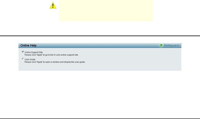
Tool Bar > Online Help
The Online Help provides two ways of online support:
Figure 4.10 – Online Help
D-Link Support Site: This will lead you to the D-Link website where you can find online resources such as updated firmware images.
User Guide: This can offer an immediate reference for the feature definition or configuration guide. Click Apply to make configuration effected.
Function Tree
All configuration options on the switch are accessed through the Setup menu on the left side of the screen. Click on the setup item that you want to configure. The following sections provide more detailed description of each feature and function.
16

4 Configuration |
DES-1210 Metro Ethernet Managed Switch User Manual |
|
|
Figure 4.11 –Function Tree
Device Information
The Device Information provides an overview of the switch, including essential information such as firmware & hardware information, and IP address.
It also offers an overall status of common software features:
STP: Click Settings to link to Configuration > Spanning Tree > STP Bridge Global Settings. Default is disabled.
Port Mirroring: Click Settings to link to Configuration > Port Mirroring. Default is disabled.
IGMP Snooping: Click Settings to link to Configuration > IGMP Snooping > IGMP Snooping. Default is disabled.
Safeguard Engine: Click Settings to link to Security > Safeguard Engine. Default is enabled.
SNMP Status: Click Settings to link to System > SNMP Settings > SNMP Global State. Default is enabled. 802.1X Status: Click Settings to link to Security > 802.1X > 802.1X Settings. Default is disabled.
802.1Q Management VLAN: Click Settings to link to Configuration > 802.1Q Management VLAN. Default is disabled.
DHCP Client: Click Settings to link to System > System Settings. Default is disabled.
17
4 Configuration |
DES-1210 Metro Ethernet Managed Switch User Manual |
|
|
Figure 4.12 – Device Information
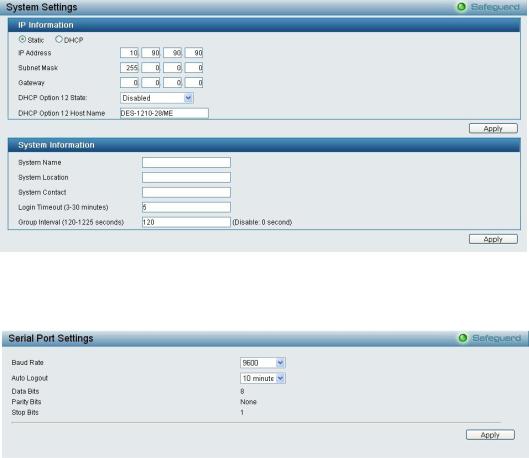
System > System Settings
The System Setting allows the user to configure the IP address and the basic system information of the Switch.
IP Information: There are two ways for the switch to obtain an IP address: Static and DHCP (Dynamic Host Configuration Protocol).
When using static mode, the IP Address, Subnet Mask, Gateway and DHCP Option 12 State can be manually configured. When using DHCP mode, the Switch will first look for a DHCP server to provide it with an IP address (including network mask and default gateway) before using the default or previously entered settings. By default the IP setting is static mode with IP address is 10.90.90.90 and subnet mask is 255.0.0.0.
System Information: By entering a System Name and System Location, the device can more easily be recognized.
Login Timeout: The Login Timeout controls the idle time-out period for security purposes, and when there is no action for a specific time span in the Web-based Management. If the current session times out (expires), the user is required a re-login before using the Web-based Management again. Selective range is from 3 to 30 minutes, and the default setting is 5 minutes.
Group Interval: The user can adjust the Group Interval to optimal frequency. Selective range is from 120 to 1225 seconds, and 0 means disabling the reporting function.
Figure 4.13 – System > System Settings
System > Serial Port Settings
The Serial Port Settings page allow user to configure the Serial Port information.
.
Figure 4.14 – System > Serial Port Settings
Baud Rate: Specifies the Baud rate for serial port. The values are 9600, 19200, 38400 and 115200 data bits. Auto Logout: Specifies the auto logout time. The values are 2 mins, 5 mins, 10 mins, 15 mins and Never Data Bits: Displays the data bits is 8.
18
4 Configuration |
DES-1210 Metro Ethernet Managed Switch User Manual |
|
|
Parity Bits: Displays the parity bits is none.
Stop Bits: Displays the stop bits is 1.
Click Apply for the settings to take effect.
System > IPv6 System Settings
The IPv6 System Settings page allow user to configure the IPv6 system information.
.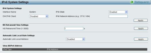
Figure 4.15 – System > IPv6 System Settings
IPv6 System Settings:
Interface Name: Displays the interface name of IPv6.
IPv6 State: Specifies the IPv6 to be enabled or disabled.
DHCPv6 Client: Specifies the DHCPv6 client to be enabled or disabled.
IPv6 Network Address: Specifies the IPv6 Network Address.
NS Retransmit Time Settings:
NS Retransmit Time (1-3600): Enter the Neighbor solicitation’s retransmit timer in second here. Specifies the NS retransmit time for IPv6. The field range is 1-3600, and default is 1 second.
Automatic Link Local State Settings:
Automatic Link Local Address: Specifies the automatic link is enabled or disabled.
Click Apply for the settings to take effect.
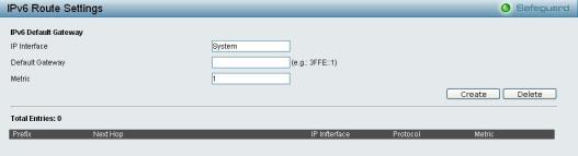
System > IPv6 Route Settings
The IPv6 Route Settings page allows user to configure the IPv6 route settings.
Figure 4.16 – System > IPv6 Route Settings
IP Interface: Specify the IP interface which to be created.
Default Gateway: The corresponding IPv6 address for the next hop Gateway address in IPv6 format..
Metric: Represents the metric value of the IP interface entered into the table. This field may read a number between 1 and 65535.
19
4 Configuration |
DES-1210 Metro Ethernet Managed Switch User Manual |
|
|
Click Create to accept the changes made, and click the Delete button to remove the entry.
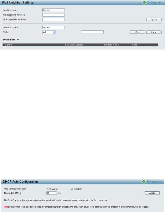
System > IPv6 Neighbor Settings
The user can configure the Switch’s IPv6 neighbor settings. The Switch’s current IPv6 neighbor settings will be displayed in the table at the bottom of this window.
Figure 4.17 – System > IPv6 Neighbor Settings
Interface Name: Enter the interface name of the IPv6 neighbor.
Neighbor IPv6 Address: Specifies the neighbor IPv6 address.
Link Layer MAC Address: Specifies the link layer MAC address.
Click Apply for the settings to take effect.
Interface Name: Specifies the interface name of the IPv6 neighbor. To search for all the current interfaces on the Switch, go to the second Interface Name field in the middle part of the window, tick the All check box. Tick the Hardware option to display all the neighbor cache entries which were written into the hardware table.
State: Use the drop-down menu to select All, Address, Static or Dynamic. When the user selects address from the drop-down menu, the user will be able to enter an IP address in the space provided next to the state option.
Click Find to locate a specific entry based on the information entered.
Click Clear to clear all the information entered in the fields.
System > DHCP Auto Configuration
This page allows you to enable the DHCP Auto Configuration feature on the Switch. When enabled, the Switch becomes a DHCP client and gets the configuration file from a TFTP server automatically on next boot up. To accomplish this, the DHCP server must deliver the TFTP server IP address and configuration file name information in the DHCP reply packet. The TFTP server must be up and running and store the necessary configuration file in its base directory when the request is received from the Switch.
Figure 4.18 – System > DHCP Auto Configuration
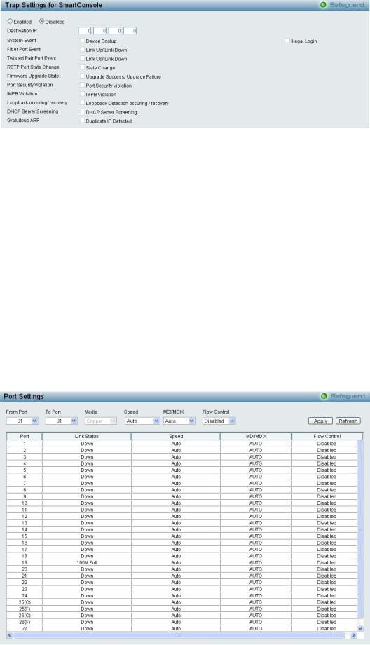
System > Trap Settings
The Trap Settings page allows user the set the difference status of SNMP notifications trapped to the Smartconsole. By default, Trap Setting is disabled.
20
4 Configuration |
DES-1210 Metro Ethernet Managed Switch User Manual |
|
|
Figure 4.19 – System > Trap Settings
You can select which event message(s) to be sent to the managing station. Destination IP: Specifies the destination IP.
System Event: Specifies the device to send bootup notifications.
Fiber Port Event: Events when fiber port connection port link up / link down. Twisted Pair Port Event: Events when pair port connection port link up / link down. RSTP Port State Change: Events of a RSTP port state changes.
Firmware Upgrade State: Information of firmware upgrade - success or failure. Port Security Violation: Events of port security violation.
IMPB Violation: Specifies the device to send notifications when IMPB violation detected.
Loopback occurring/recovery: Specifies the device to send notifications when loopback occurring / recovery.
DHCP Server Screening: Specifies the device to send notifications when DHCP server screening. Gratuitious ARP: Specifies the device to send notifications when duplicate IP were detected.
System > Port Configuration > Port Settings
In the Port Setting page, the status of all ports can be monitored and adjusted for optimum configuration. By selecting a range of ports (From Port and To Port), the Speed can be set for all selected ports by clicking Apply. Press the Refresh button to view the latest information.
Figure 4.20 – System > Port Configuration > Port Settings
21
4 Configuration |
DES-1210 Metro Ethernet Managed Switch User Manual |
|
|
Media: When port number is 25 or 26. Select the Media is Copper, Fiber_1G or Fiber_100.
Speed: Gigabit Fiber connections can operate in 1000M Full Force Mode, Auto Mode or Disabled. Copper connections can operate in Forced Mode settings (1000M Full, 100M Full, 100M Half, 10M Full, 10M Half), Auto, or Disabled. 100M Fiber connections support 100M Full Force Mode, 100M Half Force Mode, or Disabled. The default setting for all ports is Auto.
NOTE: Be sure to adjust port speed settings appropriately after changing the connected cable media types.
MDI/MDIX:
A medium dependent interface (MDI) port is an Ethernet port connection typically used on the Network Interface Card (NIC) or Integrated NIC port on a PC. Switches and hubs usually use Medium dependent interface crossover (MDIX) interface. When connecting the Switch to end stations, user have to use straight through Ethernet cables to make sure the Tx/Rx pairs match up properly. When connecting the Switch to other networking devices, a crossover cable must be used.
This switch provides a configurable MDI/MDIX function for users. The switches can be set as an MDI port in order to connect to other hubs or switches without an Ethernet crossover cable.
Auto is designed on the switch to detect if the connection is backwards, and automatically chooses MDI or MDIX to properly match the connection. The default setting is “Auto” MDI/MDIX.
Flow Control: You can enable this function to mitigate the traffic congestion. Ports configured for full-duplex use 802.3x flow control, half-duplex ports use backpressure flow control. The default setting is Disabled.
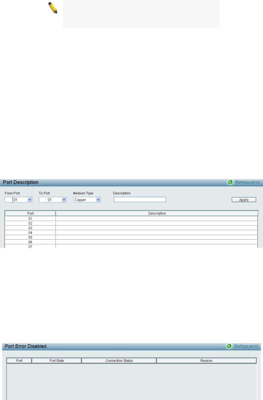
System > Port Configuration > Port Description
In the Port Description page, the user may name various ports on the Switch.
Figure 4.21 – System > Port Configuration > Port Description
From Port / To Port: Specify the range of ports to describe.
Medium Type: When port number is 25 or 26. Select the Medium Type is Copper, Fiber_1G or Fiber_100. Description: Specify the description of ports.
Click Apply to set the description in the table.
System > Port Configuration > Port Error Disabled
The Port Error Disabled page displays the information about ports that have had their connection status disabled, for reasons such as STP loopback detection or link down status.
Figure 4.22 – System > Port Configuration > Port Error Disabled
22
4 Configuration |
DES-1210 Metro Ethernet Managed Switch User Manual |
|
|
Port: Displays the port that has been error disabled.
Port State: Describes the current running state of the port, whether Enabled or Disabled.
Connection Status: This field will read the uplink status of the individual ports, whether Enabled or Disabled. Reason: Describes the reason why the port has been error-disabled, such as a STP loopback occurrence.
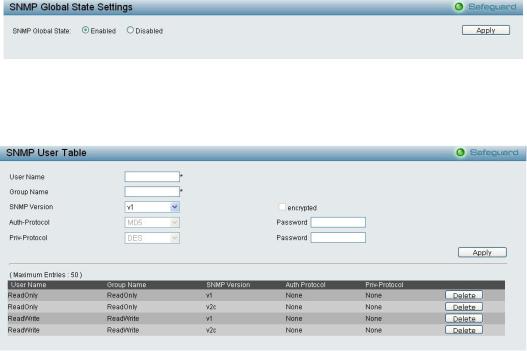
System > SNMP Settings > SNMP Global State
Simple Network Management Protocol (SNMP) is an OSI Layer 7 (Application Layer) protocol designed specifically for managing and monitoring network devices. SNMP enables network management stations to read and modify the settings of gateways, routers, switches, and other network devices. Use SNMP to configure system features for proper operation, monitor performance and detect potential problems in the Switch or LAN.
Managed devices that support SNMP include software (referred to as an agent), which runs locally on the device. A defined set of variables (managed objects) is maintained by the SNMP agent and used to manage the device. These objects are defined in a Management Information Base (MIB), which provides a standard presentation of the information controlled by the on-board SNMP agent. SNMP defines both the format of the MIB specifications and the protocol used to access this information over the network.
The default SNMP global state is disabled. Select Enable and click Apply to enable the SNMP function.
Figure 4.23 – System > SNMP Settings > SNMP Global State
System > SNMP Settings > SNMP User Table
This page is used to maintain the SNMP user table for the use of SNMPv3. SNMPv3 allows or restricts users using the MIB OID, and also encrypts the SNMP messages sent out between users and Switch.
Figure 4.24 – System > SNMP Settings > SNMP User Table
User Name: Enter a SNMP user name of up to 32 characters. Group Name: Specify the SNMP group of the SNMP user.
SNMP Version: Specify the SNMP version of the user. Only SNMPv3 encrypts the messages. Encrypt: Specifies the Encrypt is enabled or disabled when the SNMP Version is V3.
Auth-Protocol/Password: Specify either HMAC-MD5-96 or HMAC-SHA to be the authentication protocol. Enter a password for SNMPv3 encryption in the right column.
Priv-Protocol/Password: Specify either no authorization or DES 56-bit encryption and then enter a password for SNMPv3 encryption in the right column.
Click Apply to create a new SNMP user account, and click Delete to remove any existing data.
23
4 Configuration DES-1210 Metro Ethernet Managed Switch User Manual
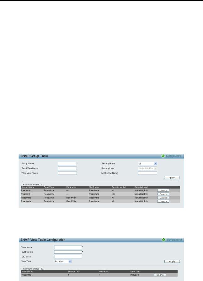
System > SNMP Settings > SNMP Group Table
This page is used to maintain the SNMP Group Table associating to the users in SNMP User Table. SNMPv3 can control MIB access policy, security policy for a user group directly.
Group Name: Specify the SNMP user group of up to 32 characters.
Read View Name: Specify a SNMP group name for users that are allowed SNMP read privileges to the Switch's SNMP agent.
Write View Name: Specify a SNMP group name for users that are allowed SNMP write privileges to the Switch's SNMP agent.
Security Model: Select the SNMP security model.
SNMPv1 - SNMPv1 does not support the security features.
SNMPv2 - SNMPv2 supports both centralized and distributed network management strategies. It includes improvements in the Structure of Management Information (SMI) and adds some security features.
SNMPv3 - SNMPv3 provides secure access to devices through a combination of authentication and encrypting packets over the network.
Security Level: This function is only available when you select SNMPv3 security level.
NoAuthNoPriv - No authorization and no encryption for packets sent between the Switch and SNMP manager.
AuthNoPriv - Authorization is required, but no encryption for packets sent between the Switch and SNMP manager.
AuthPriv – Both authorization and encryption are required for packets sent between the Switch and SNMP manger.
Notify View Name: Specify a SNMP group name for users that can receive SNMP trap messages generated by the Switch's SNMP agent.
Figure 4.25– System > SNMP Settings > SNMP Group Table
System > SNMP Settings > SNMP View Table
This page allows you to maintain SNMP views to community strings that define the MIB objects which can be accessed by a remote SNMP manager.
Figure 4.26 – System > SNMP Settings > SNMP View Table
View Name: Name of the view, up to 32 characters.
Subtree OID: The Object Identifier (OID) Subtree for the view. The OID identifies an object tree (MIB tree) that will be included or excluded from access by an SNMP manager.
24
Loading...