


 Loading...
DES-3226
Managed Standalone Fast Ethernet Switch
User’s Guide
Second Edition (July 2002)
651ES3226025
Printed In Taiwan
RECYCLABLE
Wichtige Sicherheitshinweise
1.Bitte lesen Sie sich diese Hinweise sorgfältig durch.
2.Heben Sie diese Anleitung für den spätern Gebrauch auf.
3.Vor jedem Reinigen ist das Gerät vom Stromnetz zu trennen. Vervenden Sie keine Flüssigoder Aerosolreiniger. Am besten dient ein angefeuchtetes Tuch zur Reinigung.
4.Um eine Beschädigung des Gerätes zu vermeiden sollten Sie nur Zubehörteile verwenden, die vom Hersteller zugelassen sind.
5.Das Gerät is vor Feuchtigkeit zu schützen.
6.Bei der Aufstellung des Gerätes ist auf sichern Stand zu achten. Ein Kippen oder Fallen könnte Verletzungen hervorrufen. Verwenden Sie nur sichere Standorte und beachten Sie die Aufstellhinweise des Herstellers.
7.Die Belüftungsöffnungen dienen zur Luftzirkulation die das Gerät vor Überhitzung schützt. Sorgen Sie dafür, daß diese Öffnungen nicht abgedeckt werden.
8.Beachten Sie beim Anschluß an das Stromnetz die Anschlußwerte.
9.Die Netzanschlußsteckdose muß aus Gründen der elektrischen Sicherheit einen Schutzleiterkontakt haben.
10.Verlegen Sie die Netzanschlußleitung so, daß niemand darüber fallen kann. Es sollete auch nichts auf der Leitung abgestellt werden.
11.Alle Hinweise und Warnungen die sich am Geräten befinden sind zu beachten.
12.Wird das Gerät über einen längeren Zeitraum nicht benutzt, sollten Sie es vom Stromnetz trennen. Somit wird im Falle einer Überspannung eine Beschädigung vermieden.
13.Durch die Lüftungsöffnungen dürfen niemals Gegenstände oder Flüssigkeiten in das Gerät gelangen. Dies könnte einen Brand bzw. Elektrischen Schlag auslösen.
14.Öffnen Sie niemals das Gerät. Das Gerät darf aus Gründen der elektrischen Sicherheit nur von authorisiertem Servicepersonal geöffnet werden.
15.Wenn folgende Situationen auftreten ist das Gerät vom Stromnetz zu trennen und von einer qualifizierten Servicestelle zu überprüfen: a – Netzkabel oder Netzstecker sint beschädigt.
b – Flüssigkeit ist in das Gerät eingedrungen. c – Das Gerät war Feuchtigkeit ausgesetzt.
d – Wenn das Gerät nicht der Bedienungsanleitung ensprechend funktioniert oder Sie mit Hilfe dieser Anleitung keine Verbesserung erzielen. e – Das Gerät ist gefallen und/oder das Gehäuse ist beschädigt.
f – Wenn das Gerät deutliche Anzeichen eines Defektes aufweist.
16.Bei Reparaturen dürfen nur Orginalersatzteile bzw. den Orginalteilen entsprechende Teile verwendet werden. Der Einsatz von ungeeigneten Ersatzteilen kann eine weitere Beschädigung hervorrufen.
17.Wenden Sie sich mit allen Fragen die Service und Repartur betreffen an Ihren Servicepartner. Somit stellen Sie die Betriebssicherheit des Gerätes sicher.
18.Zum Netzanschluß dieses Gerätes ist eine geprüfte Leitung zu verwenden, Für einen Nennstrom bis 6A und einem Gerätegewicht grőßer 3kg ist eine Leitung nicht leichter als H05VV-F, 3G, 0.75mm2 einzusetzen.
Trademarks
Copyright D-Link Corporation 2002. Contents subject to change without prior notice. D-Link is a registered trademark of D-Link Corporation/D-Link Systems, Inc. All other trademarks belong to their respective proprietors.
Copyright Statement
No part of this publication may be reproduced in any form or by any means or used to make any derivative such as translation, transformation, or adaptation without permission from D-Link Corporation/D-Link Systems Inc., as stipulated by the United States Copyright Act of 1976.
Limited Warranty
Hardware:
D-Link warrants its hardware products to be free from defects in workmanship and materials, under normal use and service, for the following periods measured from date of purchase from D-Link or its Authorized Reseller:
Product Type |
Warranty Period |
Complete products |
One year |
Spare parts and spare kits |
90 days |
The one-year period of warranty on complete products applies on condition that the product's Registration Card is filled out and returned to a D-Link office within ninety (90) days of purchase. A list of D-Link offices is provided at the back of this manual, together with a copy of the Registration Card. Failing such timely registration of purchase, the warranty period shall be limited to 90 days.
If the product proves defective within the applicable warranty period, D-Link will provide repair or replacement of the product. D-Link shall have the sole discretion whether to repair or replace, and replacement product may be new or reconditioned. Replacement product shall be of equivalent or better specifications, relative to the defective product, but need not be identical. Any product or part repaired by D-Link pursuant to this warranty shall have a warranty period of not less than 90 days, from date of such repair, irrespective of any earlier expiration of original warranty period. When D-Link provides replacement, then the defective product becomes the property of D-Link.
Warranty service may be obtained by contacting a D-Link office within the applicable warranty period, and requesting a Return Material Authorization (RMA) number. If a Registration Card for the product in question has not been returned to D-Link, then a proof of purchase (such as a copy of the dated purchase invoice) must be provided. If Purchaser's circumstances require special handling of warranty correction, then at the time of requesting RMA number, Purchaser may also propose special procedure as may be suitable to the case.
After an RMA number is issued, the defective product must be packaged securely in the original or other suitable shipping package to ensure that it will not be damaged in transit, and the RMA number must be prominently marked on the outside of the package. The package must be mailed or otherwise shipped to D-Link with all costs of mailing/shipping/insurance prepaid; D-Link will ordinarily reimburse Purchaser for mailing/shipping/insurance expenses incurred for return of defective product in accordance with this warranty. D-Link shall never be responsible for any software, firmware, information, or memory data of Purchaser contained in, stored on, or integrated with any product returned to D-Link pursuant to this warranty.
Any package returned to D-Link without an RMA number will be rejected and shipped back to Purchaser at Purchaser's expense, and D-Link reserves the right in such a case to levy a reasonable handling charge in addition mailing or shipping costs.
Software:
Warranty service for software products may be obtained by contacting a D-Link office within the applicable warranty period. A list of D-Link offices is provided at the back of this manual, together with a copy of the Registration Card. If a Registration Card for the product in question has not been returned to a D-Link office, then a proof of purchase (such as a copy of the dated purchase invoice) must be provided when requesting warranty service. The term "purchase" in this software warranty refers to the purchase transaction and resulting licence to use such software.
D-Link warrants that its software products will perform in substantial conformance with the applicable product documentation provided by D-Link with such software product, for a period of ninety (90) days from the date of purchase from D-Link or its Authorized Reseller. D-Link warrants the magnetic media, on which D-Link provides its software product, against failure during the same warranty period. This warranty applies to purchased software, and to replacement software provided by D-Link pursuant to this warranty, but shall not apply to any update or replacement which may be provided for download via the Internet, or to any update which may otherwise be provided free of charge.
D-Link's sole obligation under this software warranty shall be to replace any defective software product with product which substantially conforms to D-Link's applicable product documentation. Purchaser assumes responsibility for the selection of appropriate application and system/platform software and associated reference materials. D-Link makes no warranty that its
software products will work in combination with any hardware, or any application or system/platform software product provided by any third party, excepting only such products as are expressly represented, in D-Link's applicable product documentation as being compatible. D-Link's obligation under this warranty shall be a reasonable effort to provide compatibility, but D-Link shall have no obligation to provide compatibility when there is fault in the third-party hardware or software. D-Link makes no warranty that operation of its software products will be uninterrupted or absolutely error-free, and no warranty that all defects in the software product, within or without the scope of D-Link's applicable product documentation, will be corrected.
LIMITATION OF WARRANTIES
IF THE D-LINK PRODUCT DOES NOT OPERATE AS WARRANTED ABOVE, THE CUSTOMER'S SOLE REMEDY SHALL BE, AT D- LINK'S OPTION, REPAIR OR REPLACEMENT. THE FOREGOING WARRANTIES AND REMEDIES ARE EXCLUSIVE AND ARE IN LIEU OF ALL OTHER WARRANTIES, EXPRESSED OR IMPLIED, EITHER IN FACT OR BY OPERATION OF LAW, STATUTORY OR OTHERWISE, INCLUDING WARRANTIES OF MERCHANTABILITY AND FITNESS FOR A PARTICULAR PURPOSE. D-LINK NEITHER ASSUMES NOR AUTHORIZES ANY OTHER PERSON TO ASSUME FOR IT ANY OTHER LIABILITY IN CONNECTION WITH THE SALE, INSTALLATION MAINTENANCE OR USE OF D-LINK'S PRODUCTS
D-LINK SHALL NOT BE LIABLE UNDER THIS WARRANTY IF ITS TESTING AND EXAMINATION DISCLOSE THAT THE ALLEGED DEFECT IN THE PRODUCT DOES NOT EXIST OR WAS CAUSED BY THE CUSTOMER'S OR ANY THIRD PERSON'S MISUSE, NEGLECT, IMPROPER INSTALLATION OR TESTING, UNAUTHORIZED ATTEMPTS TO REPAIR, OR ANY OTHER CAUSE BEYOND THE RANGE OF THE INTENDED USE, OR BY ACCIDENT, FIRE, LIGHTNING OR OTHER HAZARD.
LIMITATION OF LIABILITY
IN NO EVENT WILL D-LINK BE LIABLE FOR ANY DAMAGES, INCLUDING LOSS OF DATA, LOSS OF PROFITS, COST OF COVER OR OTHER INCIDENTAL, CONSEQUENTIAL OR INDIRECT DAMAGES ARISING OUT THE INSTALLATION, MAINTENANCE, USE, PERFORMANCE, FAILURE OR INTERRUPTION OF A D- LINK PRODUCT, HOWEVER CAUSED AND ON ANY THEORY OF LIABILITY. THIS LIMITATION WILL APPLY EVEN IF D-LINK HAS BEEN ADVISED OF THE POSSIBILITY OF SUCH DAMAGE.
IF YOU PURCHASED A D-LINK PRODUCT IN THE UNITED STATES, SOME STATES DO NOT ALLOW THE LIMITATION OR EXCLUSION OF LIABILITY FOR INCIDENTAL OR CONSEQUENTIAL DAMAGES, SO THE ABOVE LIMITATION MAY NOT APPLY TO YOU.
D-Link Offices for Registration and Warranty Service
The product's Registration Card, provided at the back of this manual, must be sent to a D-Link office. To obtain an RMA number for warranty service as to a hardware product, or to obtain warranty service as to a software product, contact the D-Link office nearest you. An addresses/telephone/fax list of D-Link offices is provided in the back of this manual.
FCC Warning
This equipment has been tested and found to comply with the limits for a Class A digital device, pursuant to Part 15 of the FCC Rules. These limits are designed to provide reasonable protection against harmful interference when the equipment is operated in a commercial environment. This equipment generates, uses, and can radiate radio frequency energy and, if not installed and used in accordance with this user’s guide, may cause harmful interference to radio communications. Operation of this equipment in a residential area is likely to cause harmful interference in which case the user will be required to correct the interference at his own expense.
This device complies with part 15 of the FCC Rules. Operation is subject to the following two conditions: (1) This device may not cause harmful interference, and (2) this device must accept any interference received, including interference that may cause undesired operation.
CE Mark Warning
This is a Class A product. In a domestic environment, this product may cause radio interference in which case the user may be required to take adequate measures.
Warnung!
Dies ist ein Produkt der Klasse A. Im Wohnbereich kann dieses Produkt Funkstoerungen verursachen. In diesem Fall kann vom Benutzer verlangt werden, angemessene Massnahmen zu ergreifen.
Precaución!
Este es un producto de Clase A. En un entorno doméstico, puede causar interferencias de radio, en cuyo case, puede requerirse al usuario para que adopte las medidas adecuadas.
Attention!
Ceci est un produit de classe A. Dans un environnement domestique, ce produit pourrait causer des interférences radio, auquel cas l`utilisateur devrait prendre les mesures adéquates.

Attenzione!
Il presente prodotto appartiene alla classe A. Se utilizzato in ambiente domestico il prodotto può causare interferenze radio, nel cui caso è possibile che l`utente debba assumere provvedimenti adeguati.
VCCI Warning
BSMI Warning

|
Table of Contents |
About This Guide .................................................................................................................................. |
1 |
Overview of this User’s Guide ............................................................................................................. |
1 |
Introduction.......................................................................................................................................... |
2 |
Features ............................................................................................................................................. |
2 |
Ports ................................................................................................................................................ |
2 |
Performance Features......................................................................................................................... |
2 |
Management .................................................................................................................................... |
3 |
Unpacking and Setup............................................................................................................................ |
5 |
Unpacking .......................................................................................................................................... |
5 |
Installation ......................................................................................................................................... |
5 |
Desktop or Shelf Installation ............................................................................................................ |
5 |
Rack Installation.............................................................................................................................. |
6 |
Power on............................................................................................................................................. |
7 |
Power Failure ................................................................................................................................... |
7 |
Identifying External Components .......................................................................................................... |
8 |
Front Panel......................................................................................................................................... |
8 |
Rear Panel .......................................................................................................................................... |
8 |
Side Panels......................................................................................................................................... |
9 |
Optional 100BASE and 1000BASE Extension Modules....................................................................... |
9 |
LED Indicators ................................................................................................................................. |
13 |
Connecting The Switch........................................................................................................................ |
14 |
Switch to End Node .......................................................................................................................... |
14 |
Switch to Hub or Switch ................................................................................................................... |
14 |
Switch Management and Operating Concepts ..................................................................................... |
16 |
Local Console Management .............................................................................................................. |
16 |
Diagnostic (console) port (RS-232 DCE).......................................................................................... |
16 |
IP Addresses and SNMP Community Names ..................................................................................... |
17 |
Traps................................................................................................................................................ |
18 |
MIBs................................................................................................................................................. |
19 |
SNMP ............................................................................................................................................... |
19 |
Authentication ............................................................................................................................... |
19 |
Packet Forwarding............................................................................................................................ |
20 |
MAC Address Aging Time ............................................................................................................... |
20 |
Filtering............................................................................................................................................ |
20 |
Spanning Tree Protocol..................................................................................................................... |
21 |
STP Operation Levels ..................................................................................................................... |
21 |
Bridge Protocol Data Units ............................................................................................................. |
22 |
Creating a Stable STP Topology ...................................................................................................... |
23 |
STP Port States .............................................................................................................................. |
23 |
User-Changeable STP Parameters .................................................................................................. |
25 |
Illustration of STP .......................................................................................................................... |
25 |
VLANs .............................................................................................................................................. |
27 |
Notes About VLANs on the DES-3226 ............................................................................................ |
27 |
IEEE 802.1Q VLANs....................................................................................................................... |
27 |
802.1Q VLAN Packet Forwarding ................................................................................................... |
28 |
802.1Q VLAN Tags ......................................................................................................................... |
29 |
Port VLAN ID.................................................................................................................................. |
30 |
vii |
|

Tagging and Untagging................................................................................................................... |
31 |
Ingress Filtering ............................................................................................................................. |
31 |
VLANs............................................................................................................................................ |
32 |
DHCP ............................................................................................................................................... |
33 |
802.1X Port-based Network Access Control ...................................................................................... |
34 |
Configuring the Switch Using the Console Interface ............................................................................ |
37 |
Before You Start ............................................................................................................................... |
37 |
Connecting to the Switch.................................................................................................................. |
37 |
User Accounts Management ............................................................................................................. |
39 |
Save Changes ................................................................................................................................... |
41 |
Factory Reset ................................................................................................................................. |
42 |
Configuration ................................................................................................................................... |
45 |
Configure IP Address...................................................................................................................... |
45 |
Configure Switch Information and Advanced Settings .................................................................... |
47 |
Configure Ports .............................................................................................................................. |
49 |
Configure Bandwidth ..................................................................................................................... |
50 |
Configure Spanning Tree Protocol .................................................................................................. |
51 |
Configure Static (Destination-Address Filtering) Table.................................................................... |
53 |
Configure VLANs............................................................................................................................ |
55 |
Configure IGMP Snooping .............................................................................................................. |
59 |
Configure Port LACP Trunking ....................................................................................................... |
61 |
Configure Port Mirroring ................................................................................................................ |
62 |
Configure Threshold of Broadcast/Multicast/DA-Unknown Storm................................................. |
63 |
Configure Port Security .................................................................................................................. |
63 |
Configure Class of Service, Default Priority and Traffic Class ......................................................... |
64 |
Configure Port GMRP Settings........................................................................................................ |
66 |
Configure DIFFSERV Settings ........................................................................................................ |
66 |
Configure Port Access Entity .......................................................................................................... |
67 |
Network Monitoring .......................................................................................................................... |
74 |
Port Utilization ............................................................................................................................... |
74 |
Port Error Packets.......................................................................................................................... |
75 |
Port Packet Analysis....................................................................................................................... |
75 |
Browse MAC Address ..................................................................................................................... |
76 |
Switch History................................................................................................................................ |
77 |
IGMP Snooping .............................................................................................................................. |
77 |
Dynamic Group Registration Table................................................................................................. |
78 |
VLAN Status .................................................................................................................................. |
78 |
Port Access Control Statistics......................................................................................................... |
79 |
SNMP Manager Configuration........................................................................................................... |
82 |
System Utilities ................................................................................................................................ |
84 |
Upgrade Firmware from TFTP Server.............................................................................................. |
84 |
Use Configuration File on TFTP Server ........................................................................................... |
85 |
Save Settings to TFTP Server.......................................................................................................... |
85 |
Save History Log to TFTP Server..................................................................................................... |
86 |
Ping Test ........................................................................................................................................ |
86 |
Reboot .............................................................................................................................................. |
87 |
Web-Based Network Management ....................................................................................................... |
89 |
Introduction ..................................................................................................................................... |
89 |
Getting Started ................................................................................................................................. |
89 |
Configuration ................................................................................................................................... |
91 |
IP Address...................................................................................................................................... |
91 |
Switch Information......................................................................................................................... |
92 |
Advanced Settings.......................................................................................................................... |
93 |
Port Configuration.......................................................................................................................... |
95 |
Port Mirroring ................................................................................................................................ |
96 |
viii |
|

Port LACP Trunking ....................................................................................................................... |
97 |
IGMP Snooping .............................................................................................................................. |
98 |
Port GMRP ................................................................................................................................... |
100 |
Diffserv Settings........................................................................................................................... |
101 |
Spanning Tree.............................................................................................................................. |
102 |
Static Filtering Table .................................................................................................................... |
104 |
VLANs.......................................................................................................................................... |
105 |
Port Bandwidth ............................................................................................................................ |
108 |
Threshold of Broadcast ................................................................................................................ |
109 |
Port Priority.................................................................................................................................. |
110 |
Class of Traffic ............................................................................................................................. |
111 |
Class of Service ............................................................................................................................ |
111 |
Port Security ................................................................................................................................ |
112 |
PAE System Control ..................................................................................................................... |
112 |
Radius Server............................................................................................................................... |
117 |
Management................................................................................................................................... |
119 |
Security IP ................................................................................................................................... |
119 |
SNMP Manager ............................................................................................................................ |
120 |
Trap Manager............................................................................................................................... |
120 |
User Accounts.............................................................................................................................. |
121 |
Monitoring...................................................................................................................................... |
122 |
Port Utilization ............................................................................................................................. |
122 |
Packets ........................................................................................................................................ |
123 |
Errors .......................................................................................................................................... |
127 |
Size .............................................................................................................................................. |
131 |
MAC Address ............................................................................................................................... |
133 |
IGMP Snooping ............................................................................................................................ |
135 |
Dynamic Group Registration ........................................................................................................ |
135 |
VLAN Status ................................................................................................................................ |
136 |
Port Access Control ...................................................................................................................... |
136 |
Maintenance................................................................................................................................... |
141 |
TFTP Services............................................................................................................................... |
141 |
Switch History.............................................................................................................................. |
144 |
Ping Test ...................................................................................................................................... |
145 |
Save Changes............................................................................................................................... |
145 |
Factory Reset ............................................................................................................................... |
146 |
Restart System............................................................................................................................. |
146 |
Connection Timeout ..................................................................................................................... |
147 |
Logout.......................................................................................................................................... |
147 |
Help................................................................................................................................................ |
147 |
Technical Specifications .................................................................................................................... |
148 |
RJ-45 Pin Specification ..................................................................................................................... |
150 |
Runtime Switching Software Default Settings.................................................................................... |
152 |
Understanding and Troubleshooting the Spanning Tree Protocol....................................................... |
153 |
Blocking State.............................................................................................................................. |
153 |
Listening State ............................................................................................................................. |
154 |
Learning State.............................................................................................................................. |
155 |
Forwarding State.......................................................................................................................... |
156 |
Disabled State.............................................................................................................................. |
156 |
Troubleshooting STP....................................................................................................................... |
158 |
Spanning Tree Protocol Failure .................................................................................................... |
158 |
Full/Half Duplex Mismatch.......................................................................................................... |
158 |
Unidirectional Link ...................................................................................................................... |
159 |
ix |
|

Packet Corruption........................................................................................................................ |
160 |
Resource Errors ........................................................................................................................... |
160 |
Identifying a Data Loop ................................................................................................................ |
160 |
Avoiding Trouble .......................................................................................................................... |
160 |
Brief Review of Bitwise Logical Operations......................................................................................... |
163 |
Index................................................................................................................................................. |
164 |
x
DES-3226 NWay Standalone Fast Ethernet Switch User’s Guide
ABOUT THIS GUIDE
This User’s Guide tells you how to install your DES-3226, how to connect it to your Ethernet/Fast Ethernet/Gigabit Ethernet network, and how to set its configuration using the built-in console interface.
Overview of this User’s Guide
•Chapter 1, “Introduction.” Describes the Switch and its features.
•Chapter 2, “Unpacking and Setup.” Helps you get started with the basic installation of the Switch.
•Chapter 3, “Identifying External Components.” Describes the front panel, rear panel, optional plug-in modules, and LED indicators of the Switch.
•Chapter 4, “Connecting the Switch.” Tells how you can connect the Switch to your Ethernet/Fast Ethernet/Gigabit Ethernet network.
•Chapter 5, “Switch Management and Operating Concepts.” Talks about Local Console Management via the RS-232 DCE console port and other aspects about how to manage the Switch.
•Chapter 6, “Using the Console Interface.” Tells how to use the built-in console interface to change, set, and monitor Switch performance and security.
•Chapter 7, “Web-Based Network Management.” Tells how to manage the Switch through an Internet browser.
•Appendix A, “Technical Specifications.” Lists the technical specifications of the Switch.
•Appendix B, “RJ-45 Pin Specifications.” Shows the details and pin assignments for the RJ-45 receptacle/connector.
•Appendix C, “Factory Default Settings.”
•Appendix D, “Understanding and Troubleshooting the Spanning Tree Protocol.”
•Appendix E, “Brief Review of Bitwise Logical Operations.”
1

DES-3226 NWay Standalone Fast Ethernet Switch User’s Guide
1
INTRODUCTION
This section describes the features of the DES-3226.
Features
The Switch was designed for easy installation and high performance in an environment where traffic on the network and the number of users increases continuously.
Switch features include:
Ports
•24 (DES-3226) high performance NWay (MDI-II/MDI-X) ports for connecting to end stations, servers and hubs. Every port can be used for an uplink connection.
•All UTP ports can auto-negotiate (NWay) between 10Mbps/100Mbps, half-duplex or full duplex, and feature flow control.
•One front panel slide-in module interface for a 1-port 100BASE-FX (2Km), 2-port 100BASE-FX (2Km), 1-port 100BASE-FL (15Km), 2-port 100BASE-FL (15Km), 2-port 1000BASE-SX, 2-port 1000BASE-LX, 2-port 1000BASE-T, or 2-port GBIC to connect to another switch, server or network backbone.
•RS-232 DCE Diagnostic port (console port) for setting up and managing the Switch via a connection to a console terminal or PC using a terminal emulation program.
Performance Features
•8.8 Gbps switching fabric capacity
•Store and forward switching scheme.
•Full and half-duplex for both 10Mbps and 100Mbps connections. Full duplex allows the switch port to simultaneously transmit and receive data, and only works with connections to full-duplex capable end stations and switches. Connections to hubs must take place at half duplex.
•Auto-polarity detection and correction of incorrect polarity on the transmit and receive twistedpair at each port.
•Data forwarding rate 14,880 pps per port at 100% of wire-speed for 10Mbps speed.
•Data forwarding rate 148,800 pps per port at 100% of wire-speed for 100Mbps speed.
2

DES-3226 NWay Standalone Fast Ethernet Switch User’s Guide
•Data filtering rate eliminates all error packets, runts, etc. at 14,880 pps per port at 100% of wirespeed for 10Mbps speed.
•Data filtering rate eliminates all error packets, runts, etc. at 148,800 pps per port at 100% of wire-speed for 100Mbps speed.
•8K active MAC address entry table per device with automatic learning and aging (10 to 1000000 seconds).
•8 MB packet buffer per device.
•802.1D Spanning Tree support.
•802.1Q Tagged VLAN support, including GVRP (GARP VLAN Registration Protocol) support for automatic VLAN configuration distribution. All the supported VLANs (including dynamic joined VLANs by GVRP and user-defined VLANs and the one reserved VLAN) can be up to 255.
•IGMP Snooping support.
•Port trunking support.
•RADIUS client support.
•EAPOL support.
•802.1X port-based authentication support. Authentication methods: EAP MD5-Challenge (RFC 1994) and EAP TLS Authentication Protocol (RFC 2716).
Management
•RS-232 console port for out-of-band network management via a console terminal.
•Spanning Tree Algorithm Protocol for creation of alternative backup paths and prevention of network loops.
•SNMP V.1/V.2C Agent.
•Fully configurable either in-band or out-of-band control via SNMP based software.
•Flash memory for software upgrades. This can be done in-band via TFTP or out-of-band via the console.
•Built-in SNMP management:
Bridge MIB (RFC 1493)
MIB-II (RFC 1213)
802.1p MIB (RFC 2674)
802.1q MIB (RFC 2674)
Entity MIB (RFC 2737)
IF-MIB (RFC 2233)
Ether-Like MIB (RFC 2358) –dot3StatsTable
SNMP V.2-MIB (RFC 1907)
3

DES-3226 NWay Standalone Fast Ethernet Switch User’s Guide
802.1X MIB
Enterprise MIB
Mini-RMON MIB (RFC 1757) – 4 groups. The RMON specification defines the Counters for the Receive functions only. However, the DES-3226 implements counters for both receive and transmit functions.
•Supports Web-based management.
•TFTP support.
•BOOTP support.
•DHCP Client support.
•Password enabled.
•Telnet remote control console support.
4

DES-3226 NWay Standalone Fast Ethernet Switch User’s Guide
2
UNPACKING AND SETUP
This chapter provides unpacking and setup information for the Switch.
Unpacking
Open the shipping carton of the Switch and carefully unpack its contents. The carton should contain the following items:
•One DES-3226 24-Port NWay Standalone Fast Ethernet Switch
•Mounting kit: 2 mounting brackets and screws
•Four rubber feet with adhesive backing
•One AC power cord
•This User’s Guide with Registration Card
If any item is found missing or damaged, please contact your local reseller for replacement.
Installation
Use the following guidelines when choosing a place to install the Switch:
•The surface must support at least 3 kg.
•The power outlet should be within 1.82 meters (6 feet) of the device.
•Visually inspect the power cord and see that it is secured to the AC power connector.
•Make sure that there is proper heat dissipation from and adequate ventilation around the Switch. Do not place heavy objects on the Switch.
Desktop or Shelf Installation
When installing the Switch on a desktop or shelf, the rubber feet included with the device should first be attached. Attach these cushioning feet on the bottom at each corner of the device. Allow adequate space for ventilation between the device and the objects around it.
5

DES-3226 NWay Standalone Fast Ethernet Switch User’s Guide
Figure 2-1. Installing rubber feet for desktop installation
Rack Installation
The DES-3226 can be mounted in an EIA standard-sized, 19-inch rack, which can be placed in a wiring closet with other equipment. To install, attach the mounting brackets on the Switch’s side panels (one on each side) and secure them with the screws provided.
Figure 2- 2A. Attaching the mounting brackets to the Switch
Then, use the screws provided with the equipment rack to mount the Switch on the rack.
6
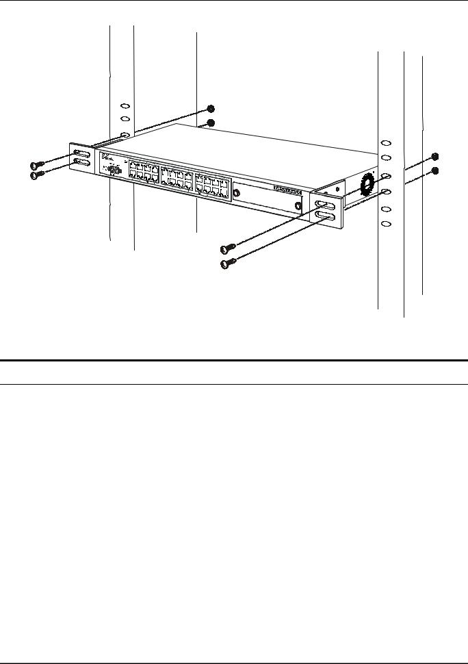
DES-3226 NWay Standalone Fast Ethernet Switch User’s Guide
Figure 2-2B. Installing the Switch in an equipment rack
Power on
The Switch can be used with AC power supply 100-240 VAC, 50 - 60 Hz. The Switch’s power supply will adjust to the local power source automatically and may be powered on without having any or all LAN segment cables connected.
After the Switch is plugged in, the LED indicators should respond as follows:
•All LED indicators will momentarily blink. This blinking of the LED indicators represents a reset of the system.
•The power LED indicator will blink while the Switch loads onboard software and performs a selftest. After approximately 20 seconds, the LED will light again to indicate the switch is in a ready state.
Power Failure
As a precaution in the event of a power failure, unplug the Switch. When power is resumed, plug the Switch back in.
7
DES-3226 NWay Standalone Fast Ethernet Switch User’s Guide
3
IDENTIFYING EXTERNAL COMPONENTS
This chapter describes the front panel, rear panel, side panels, optional plug-in modules, and LED indicators of the DES-3226.
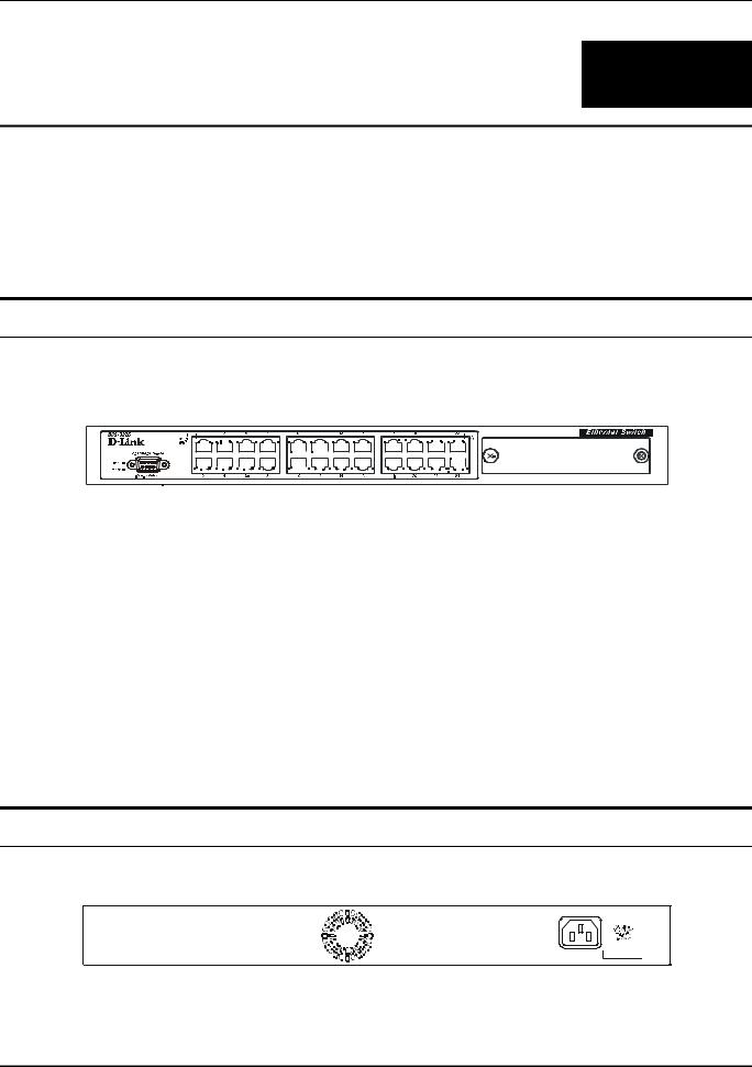
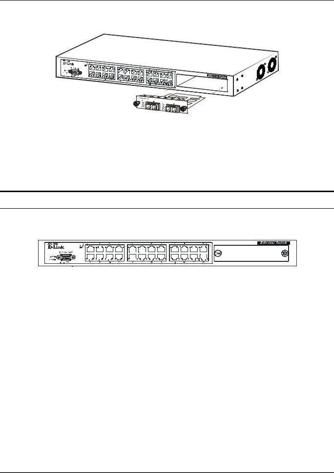
Front Panel
The front panel of the Switch consists of LED indicators, an RS-232 communication port, a slide-in module slot, and either 10, 18 or 24 MDI-X/MDI-II Ethernet/Fast Ethernet (10/100 Mbps) ports, each of which is capable of making an uplink connection.
Figure 3-1. Front panel view of the Switch
•Comprehensive LED indicators display the status of the Switch and the network (see the LED Indicators section below).
•An RS-232 DCE console port for setting up and managing the Switch via a connection to a console terminal or PC using a terminal emulation program.
•A front-panel slide-in module slot can accommodate a 1-port 100BASE-FX (2Km), 2-port 100BASE-FX (2Km), 1-port 100BASE-FL (15Km), 2-port 100BASE-FL (15Km), 2-port 1000BASESX, 2-port 1000BASE-LX, 2-port 1000BASE-T, or 2-port GBIC module to connect to another switch, server or network backbone.
•Twenty-four high-performance, NWay Ethernet ports all of which operate at 10/100 Mbps for connections to end stations, servers and hubs. All ports can auto-negotiate between 10Mbps or 100Mbps and full or half duplex.
Rear Panel
The rear panel of the Switch contains an AC power connector.
Figure 3-2. Rear panel view of the Switch
8
DES-3226 NWay Standalone Fast Ethernet Switch User’s Guide
•The AC power connector is a standard three-pronged connector that supports the power cord. Plug-in the female connector of the provided power cord into this socket, and the male side of the cord into a power outlet. Supported input voltages range from 100 ~ 240 VAC at 50 ~ 60 Hz.
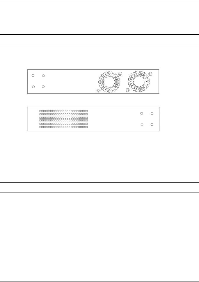
Side Panels
The right side panel of the Switch contains two system fans (see the top part of the diagram below). The left side panel contains heat vents.
Figure 3-3. Side panel views of the Switch
•The system fans are used to dissipate heat. The sides of the system also provide heat vents to serve the same purpose. Do not block these openings, and leave at least 6 inches of space at the rear and sides of the switch for proper ventilation. Be reminded that without proper heat dissipation and air circulation, system components might overheat, which could lead to system failure.
Optional 100BASE and 1000BASE Extension Modules
The Switch is able to accommodate a range of optional plug-in modules in order to increase functionality and performance. These modules must be purchased separately.
9

DES-3226 NWay Standalone Fast Ethernet Switch User’s Guide
100BASE-FX Module (2Km)
Figure 3-4. Optional 100BASE 1-port front panel module
•One 100BASE-FX (with SC type connector) Fiber port.
•Fully compliant with IEEE802.3u.
•Support Full-duplex operation only.
•IEEE 802.3x compliant Flow Control support for full duplex.
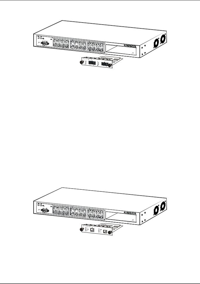
100BASE-FX Module (2Km)
Figure 3-5. Optional 100BASE 2-port front panel module
•Two 100BASE-FX (with SC type connector) Fiber ports.
•Fully compliant with IEEE802.3u.
•Support Full-duplex operation only.
•IEEE 802.3x compliant Flow Control support for full duplex.
100BASE-FL Module (15Km)
Figure 3-6. Optional 100BASE 1-port front panel module
10
DES-3226 NWay Standalone Fast Ethernet Switch User’s Guide
•One 100BASE-FL (with SC type connector) port.
•Fully compliant with IEEE802.3u.
•Support Full-duplex operation only.
•IEEE 802.3x compliant Flow Control support for full duplex.
100BASE-FL Module (15Km)
Figure 3-7. Optional 100BASE 2-port front panel module
•Two 100BASE-FL (with SC type connector) ports.
•Fully compliant with IEEE802.3u.
•Support Full-duplex operation only.
•IEEE 802.3x compliant Flow Control support for full duplex.
1000BASE-LX Gigabit Module
Figure 3-8. Optional 1000BASE-LX 2-port front panel module
•Two 1000BASE-LX ports.
•Connects to 1000BASE-LX devices at full duplex or auto.
•Allows connections up to 5 km in length using single-mode fiber optic cable.
11
DES-3226 NWay Standalone Fast Ethernet Switch User’s Guide
1000BASE-SX Gigabit Module
Figure 3-9. Optional 1000BASE-SX 2-port front panel module
•Two 1000BASE-SX ports.
•Connects to 1000BASE-SX devices at full duplex or auto.
•IEEE 802.3x compliant Flow Control support for full duplex.
•Supports multi-mode fiber-optic cable connections of up to 2 km.
•Allows connections using multi-mode fiber optic cable in the following configurations:
|
62.5µm |
62.5µm |
50µm |
50µm |
|
|
|
|
|
Modal bandwidth |
160 |
200 |
400 |
500 |
(min. overfilled launch) |
|
|
|
|
Unit: MHz*km |
|
|
|
|
|
|
|
|
|
Operating distance |
220 |
275 |
500 |
550 |
Unit: meters |
|
|
|
|
|
|
|
|
|
Channel insertion loss |
2.33 |
2.53 |
3.25 |
3.43 |
Unit: dB |
|
|
|
|
|
|
|
|
|
1000BASE-T Copper Gigabit Module
Figure 3-10. Optional 1000BASE-T Copper 2-port front panel module
•Two 1000BASE-T Copper ports.
•Connects to 1000BASE-T devices at 1000M/full duplex, 100M/full duplex, 100M/half duplex, and Auto.
•Supports Category 5+ or higher cable connections of up to 100 meters.
12
DES-3226 NWay Standalone Fast Ethernet Switch User’s Guide
1000BASE GBIC Module
Figure 3-11. Optional 1000BASE GBIC 2-port front panel module
•Two 1000BASE GBIC ports.
•Connects to GBIC devices at full duplex only.
•Allows multi-mode fiber optic cable runs of up to 550m in full-duplex mode (only).
LED Indicators
The LED indicators of the Switch include Power, Console, Speed, and Link/Act. The following shows the LED indicators for the Switch along with an explanation of each indicator.
Figure 3-12. The LED indicators
•Power – This indicator on the front panel should be lit during the Power-On Self Test (POST). It will light green approximately 2 seconds after the switch is powered on to indicate the ready state of the device.
•Console – This indicator is lit green when the Switch is being managed via out-of-band/local console management through the RS-232 console port using a straight-through serial cable.
•Speed – On the right of each twisted pair port, this LED will light when the corresponding port is operating at 100 Mbps. An unlit LED indicates a connection speed of 10 Mbps.
•Link/Act – These indicators are located to the left of each port. They are lit when there is a secure connection (or link) to a device at any of the ports. The LEDs blink whenever there is reception or transmission (i.e. Activity--Act) of data occurring at a port.
13
DES-3226 NWay Standalone Fast Ethernet Switch User’s Guide
4
CONNECTING THE SWITCH
This chapter describes how to connect the DES-3226 to your Ethernet/Fast Ethernet/Gigabit Ethernet network.
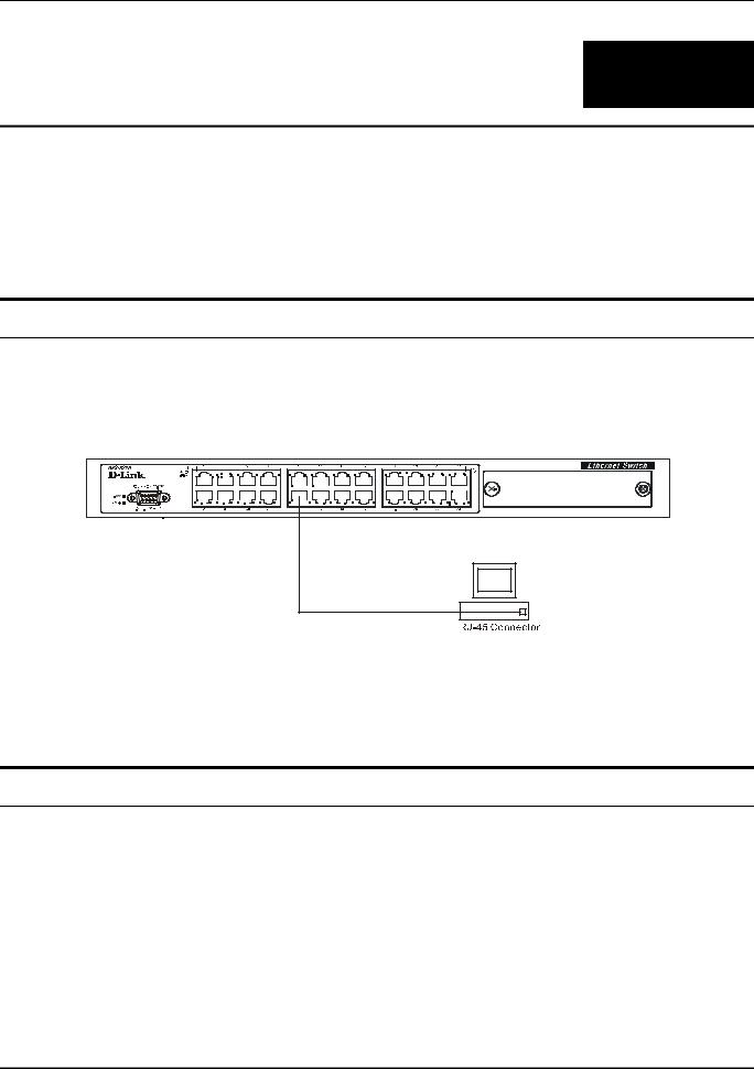
Switch to End Node
End nodes include PCs outfitted with a 10, 100 or 10/100 Mbps RJ-45 Ethernet/Fast Ethernet/Gigabit Ethernet Network Interface Card (NIC) and most routers.
An end node can be connected to the Switch via a two-pair Category 3, 4, or 5 UTP/STP cable. The end node should be connected to any of the ports of the Switch.
Figure 4-1. Switch connected to an End Node
The Link/Act LEDs for each UTP port light green when the link is valid. The LED on the right side of the port indicates port speed. It will light for 100 Mbps connections only. A blinking LED on the left side indicates packet activity on that port.
Switch to Hub or Switch
These connections can be accomplished in a number of ways using a normal cable.
•A 10BASE-T hub or switch can be connected to the Switch via a two-pair Category 3, 4 or 5 UTP/STP cable.
•A 100BASE-TX hub or switch can be connected to the Switch via a two-pair Category 5 UTP/STP cable.
14

DES-3226 NWay Standalone Fast Ethernet Switch User’s Guide
Figure 4-2. Switch connected to a normal (non-Uplink) port on a hub or switch using a straight or crossover cable
15

DES-3226 NWay Standalone Fast Ethernet Switch User’s Guide
5
SWITCH MANAGEMENT AND OPERATING
CONCEPTS
This chapter discusses many of the concepts and features used to manage the Switch, as well as the concepts necessary for the user to understand the functioning of the switch. Further, this chapter explains many important points regarding these features.
Configuring the Switch to implement these concepts and make use of its many features is discussed in detail in the next chapters.
Local Console Management
A local console is a terminal or a workstation running a terminal emulation program that is connected directly to the switch via the RS-232 console port on the front of the Switch. A console connection is referred to as an ‘Out-of-Band’ connection, meaning that console is connected to the Switch using a different circuit than that used for normal network communications. So, the console can be used to set up and manage the Switch even if the network is down.
Local console management uses the terminal connection to operate the console program built-in to the Switch (see Chapter 6, “Using the Console Interface”). A network administrator can manage, control and monitor the switch from the console program.
The DES-3226 contains a CPU, memory for data storage, flash memory for configuration data, operational programs, and SNMP agent firmware. These components allow the Switch to be actively managed and monitored from either the console port or the network itself (out-of-band, or in-band).
Diagnostic (console) port (RS-232 DCE)
Out-of-band management requires connecting a terminal, such as a VT-100 or a PC running a terminal emulation program (such as HyperTerminal, which is automatically installed with Microsoft Windows) a to the RS-232 DCE console port of the Switch. Switch management using the RS-232 DCE console port is called Local Console Management to differentiate it from management performed via management platforms, such as D-View, HP OpenView, etc.
The console port is set at the factory for the following configuration:
• |
Baud rate: |
9,600 |
• |
Data width: |
8 bits |
• |
Parity: |
none |
• |
Stop bits: |
1 |
• |
Flow Control |
None |
16
DES-3226 NWay Standalone Fast Ethernet Switch User’s Guide
Make sure the terminal or PC you are using to make this connection is configured to match these settings.
If you are having problems making this connection on a PC, make sure the emulation is set to VT100. If you still don’t see anything, try hitting <Ctrl> + r to refresh the screen.
IP Addresses and SNMP Community Names
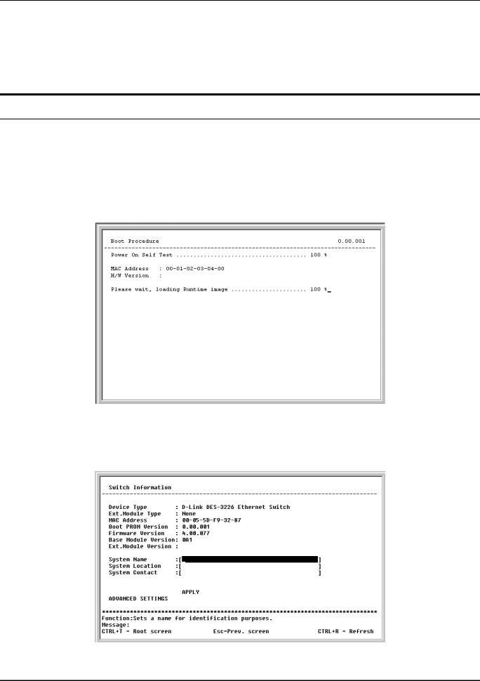
Each Switch must be assigned its own IP Address, which is used for communication with an SNMP network manager or other TCP/IP application (for example BOOTP, TFTP). The Switch’s default IP address is 10.90.90.90. You can change the default Switch IP Address to meet the specification of your networking address scheme.
The Switch is also assigned a unique MAC address by the factory. This MAC address cannot be changed, and can be found from the initial boot console screen – shown below.
Figure 5-1. Boot Procedure screen
The Switch’s MAC address can also be found from the console program under the Switch Information menu item, as shown below.
Figure 5-2. Switch Information menu
17

DES-3226 NWay Standalone Fast Ethernet Switch User’s Guide
In addition, you can also set an IP Address for a gateway router. This becomes necessary when the network management station is located on a different IP network from the Switch, making it necessary for management packets to go through a router to reach the network manager, and vice-versa.
For security, you can set in the Switch a list of IP Addresses of the network managers that allow you to manage the Switch. You can also change the default SNMP Community Strings in the Switch and set the access rights of these Community Strings. In addition, a VLAN may be designated as a Management VLAN.
Traps
Traps are messages that alert you of events that occur on the Switch. The events can be as serious as a reboot (someone accidentally turned OFF the Switch), or less serious like a port status change. The Switch generates traps and sends them to the network manager (trap recipient).
Trap recipients are special users of the network who are given certain rights and access in overseeing the maintenance of the network. Trap recipients will receive traps sent from the Switch; they must immediately take certain actions to avoid future failure or breakdown of the network.
You can also specify which network managers may receive traps from the Switch by entering a list of the IP addresses of authorized network managers. Up to four trap recipient IP addresses, and four corresponding SNMP community strings can be entered.
SNMP community strings function like passwords in that the community string entered for a given IP address must be used in the management station software, or a trap will be sent.
The following are trap types the Switch can send to a trap recipient:
•Cold Start – This trap signifies that the Switch has been powered up and initialized such that software settings are reconfigured and hardware systems are rebooted. A cold start is different from a factory reset in that configuration settings saved to non-volatile RAM used to reconfigure the switch.
•Warm Start – This trap signifies that the Switch has been rebooted, however the POST (Power On Self-Test) is skipped.
•Authentication Failure – This trap signifies that someone has tried to logon to the switch using an invalid SNMP community string. The Switch automatically stores the source IP address of the unauthorized user.
•New Root – This trap indicates that the Switch has become the new root of the Spanning Tree, the trap is sent by the switch soon after its election as the new root. This implies that upon expiration of the Topology Change Timer the new root trap is sent out immediately after the Switch’s election as the new root.
•Topology Change (STP) – A Topology Change trap is sent by the Switch when any of its configured ports transitions from the Learning state to the Forwarding state, or from the Forwarding state to the Blocking state. The trap is not sent if a new root trap is sent for the same transition.
•Link Up – This trap is sent whenever the link of a port changes from link down to link up.
•Link Down – This trap is sent whenever the link of a port changes from link up to link down.
18

DES-3226 NWay Standalone Fast Ethernet Switch User’s Guide
MIBs
Management and counter information are stored in the Switch in the Management Information Base (MIB). The Switch uses the standard MIB-II Management Information Base module. Consequently, values for MIB objects can be retrieved from any SNMP-based network management software. In addition to the standard MIB-II, the Switch also supports its own proprietary enterprise MIB as an extended Management Information Base. These MIBs may also be retrieved by specifying the MIB’s Object-Identity (OID) at the network manager. MIB values can be either read-only or read-write.
Read-only MIBs variables can be either constants that are programmed into the Switch, or variables that change while the Switch is in operation. Examples of read-only constants are the number of port and type of ports. Examples of read-only variables are the statistics counters such as the number of errors that have occurred, or how many kilobytes of data have been received and forwarded through a port.
Read-write MIBs are variables usually related to user-customized configurations. Examples of these are the Switch’s IP Address, Spanning Tree Algorithm parameters, and port status.
If you use a third-party vendors’ SNMP software to manage the Switch, a diskette listing the Switch’s propriety enterprise MIBs can be obtained by request. If your software provides functions to browse or modify MIBs, you can also get the MIB values and change them (if the MIBs’ attributes permit the write operation). This process however can be quite involved, since you must know the MIB OIDs and retrieve them one by one.
SNMP
The Simple Network Management Protocol (SNMP) is an OSI layer 7 (the application layer) protocol for remotely monitoring and configuring network devices. SNMP enables network management stations to read and modify the settings of gateways, routers, switches, and other network devices. SNMP can be used to perform many of the same functions as a directly connected console, or can be used within an integrated network management software package such as HP OpenView or DView.
SNMP performs the following functions:
•Sending and receiving SNMP packets through the IP protocol.
•Collecting information about the status and current configuration of network devices.
•Modifying the configuration of network devices.
The DES-3226 has a software program called an ‘agent’ that processes SNMP requests, but the user program that makes the requests and collects the responses runs on a management station (a designated computer on the network). The SNMP agent and the user program both use the UDP/IP protocol to exchange packets.
Authentication
The authentication protocol ensures that both the router SNMP agent and the remote user SNMP application program discard packets from unauthorized users. Authentication is accomplished using ‘community strings’, which function like passwords. The remote user SNMP application and the router SNMP must use the same community string. SNMP community strings of up to 20 characters may be entered under the Remote Management Setup menu of the console program.
19

DES-3226 NWay Standalone Fast Ethernet Switch User’s Guide
Packet Forwarding
The Switch enters the relationship between destination MAC or IP addresses and the Ethernet port or gateway router the destination resides on into its forwarding table. This information is then used to forward packets. This reduces the traffic congestion on the network, because packets, instead of being transmitted to all ports, are transmitted to the destination port only. Example: if Port 1 receives a packet destined for a station on Port 2, the Switch transmits that packet through Port 2 only, and transmits nothing through the other ports. This process is referred to as ‘learning’ the network topology.
MAC Address Aging Time
The Aging Time affects the learning process of the Switch. Dynamic forwarding table entries, which are made up of the source and destination MAC addresses and their associated port numbers, are deleted from the table if they are not accessed within the aging time.
The aging time can be from 10 to 1,000,000 seconds with a default value of 300 seconds. A very long aging time can result in dynamic forwarding table entries that are out-of-date or no longer exist. This may cause incorrect packet forwarding decisions by the Switch.
If the Aging Time is too short however, many entries may be aged out too soon. This will result in a high percentage of received packets whose source addresses cannot be found in the forwarding table, in which case the switch will broadcast the packet to all ports, negating many of the benefits of having a switch.
Static forwarding entries are not affected by the aging time.
Filtering
The Switch uses a filtering database to segment the network and control communication between segments. It can also filter packets off the network for intrusion control. Static filtering entries can be made by MAC Address or IP Address filtering.
Each port on the Switch is a unique collision domain and the switch filters (discards) packets whose destination lies on the same port as where it originated. This keeps local packets from disrupting communications on other parts of the network.
For intrusion control, whenever a Switch encounters a packet originating from or destined to a MAC address or an IP Address entered into the filter table, the switch will discard the packet.
Some filtering is done automatically by the Switch:
•Dynamic filtering – automatic learning and aging of MAC addresses and their location on the network. Filtering occurs to keep local traffic confined to its segment.
•Filtering done by the Spanning Tree Protocol that can filter packets based on topology, making sure that signal loops don’t occur.
•Filtering done for VLAN integrity. Packets from a member of a VLAN (VLAN 2, for example) destined for a device on another VLAN (VLAN 3) will be filtered.
Some filtering requires the manual entry of information into a filtering table:
20
Loading...