


D-Link
DGS-1250-52XMP
48 10/100/1000Base-T PoE ports + 4 10GBase-X SFP+ ports L2 Smart Managed Switch
Настраиваемый коммутатор 2 уровня с 48 портами 10/100/1000Base-T и
4 портами 10GBase-X SFP+ (48 портов с поддержкой PoE 802.3af/802.3at (30 Вт), PoE-бюджет 370 Вт)
Quick Installation Guide Краткое руководство по установке
Information in this document is subject to change without notice. © 2019 D-Link Corporation. All rights reserved.
Package Contents
Open the shipping carton of the Switch and carefully unpack its contents. If any item is missing or damaged, please contact your local D-Link reseller for replacement. The carton should contain the following items:
One DGS-1250-52XMP switch
One AC power cord
One console cable (RJ-45 to RS-232)
One rack mounting kit (two brackets and screws)
Four rubber feet with adhesive backing
One power cord retainer set
One Quick Installation Guide
One CD
Installation Guidelines
This section will discuss the hardware installation guidelines that the user must follow in order to properly and safely install this switch into the appropriate environment.
Visually inspect the power cord and see that it is fully secured to both the power connector, on the Switch, and the electrical outlet that supplies power.
Install the Switch in a fairly cool and dry place within the acceptable operating temperature and humidity ranges.
Install the Switch in a site free from strong electromagnetic field generators such as motors, vibration, dust, and direct exposure to sunlight.
Installing the Switch without a Rack
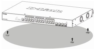
This section is used to guide the user through installing the Switch in an area other than a switch rack. Attach the included rubber feet to the bottom of the Switch. Take note that there should be marked blocks on the bottom of the Switch to indicate where to attach the rubber feet. These markings are usually found in each corner on the bottom of the device. The rubber feet cushion the Switch, protecting the casing from scratches and preventing it from scratching other surfaces.
Figure 1 — Attaching rubber feet to the Switch
2
Install the Switch on a sturdy, level surface that can support the weight of the Switch. Do not place any heavy objects on the Switch. The power outlet should be within 1.82 meters (6 feet) of the Switch. Make sure that there is proper heat dissipation from and adequate ventilation around the Switch. Leave at least 10 cm (4 inches) of space at the front, sides, and rear of the Switch for ventilation.
Installing the Switch in a Standard 19'' Rack
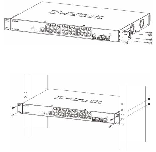
This section is used to guide the user through installing the Switch into a switch rack. The Switch can be mounted in a standard 19"(1U) rack using the provided mounting brackets. Fasten the mounting brackets to the sides of the Switch using the screws provided.
Figure 2 — Attaching rack-mount brackets to the Switch
Fasten the mounting brackets in any available open space in the rack using the screws provided with the rack.
Figure 3 — Installing the Switch in a Rack
Installing Transceivers into the Transceiver Ports
The Switch is equipped with Enhanced Small Form-factor Pluggable (SFP+) ports that can be used to connect various other networking devices to this switch that do not support the standard RJ-45 wiring connection. These ports are generally used to connect this switch to optical fiber connections and can be used to connect devices to the Switch over great distances. The maximum distance that the RJ-45 wiring connection can reach is 100 meters. Fiber optic connections can span several kilometers.
3

Figure 4 — Inserting transceivers into the transceiver ports
Power On (AC Power)
Plug one end of the AC power cord into the power socket of the Switch and the other end into the local power source outlet.
Power Failure (AC Power)
In the event of a power failure, just as a precaution, unplug the power cord from the Switch. After the power returns, plug the power cord back into the power socket of the Switch.
Installing Power Cord Retainer
To prevent accidental removal of the AC power cord, it is recommended to install the power cord retainer together with the power cord.
With the rough side facing down, insert the tie wrap into the hole below the power socket.
Figure 5 — Insert Tie Wrap into the Switch
Plug the AC power cord into the power socket of the Switch.
4
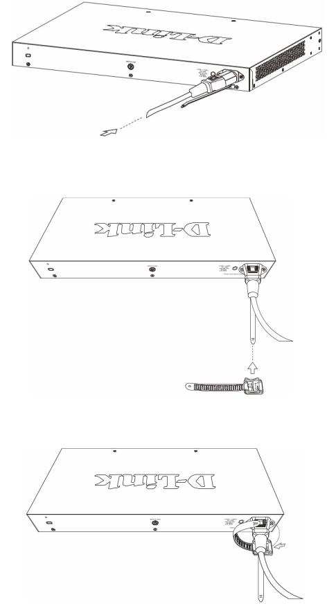
Figure 6 — Connect the power cord to the Switch
Slide the retainer through the tie wrap until the end of the cord.
Figure 7 — Slide the Retainer through the Tie Wrap
Circle the tie of the retainer around the power cord and into the locker of the retainer.
Figure 8 — Circle around the power cord
5
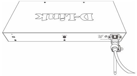
Fasten the tie of the retainer until the power cord is secured.
Figure 9 — Secure the power cord
Management Options
This Switch provides multiple access platforms that can be used to configure, manage, and monitor networking features available on this Switch. Currently there are three management platforms available which are described below.
Command Line Interface (CLI)
This Switch can be managed, out-of-band, by using the console port on the front panel of the Switch.
SNMP-based Management
The Switch can be managed with an SNMP-compatible console program. The Switch supports SNMP v1, SNMPv2c and SNMPv3.
Web User Interface (Web UI)
The Web UI can be accessed from any computer running web browsing software. This management interface is a more graphical representation of the features that can be viewed and configured on this Switch.
Connecting to the Console Port
The front panel of the Switch provides an RJ-45 console port to connect a remote system for monitoring and configuring the Switch.
To use the RJ-45 console port, the following equipment is needed:
A terminal or a computer with both an RS-232 serial port and terminal emulation software
A console cable with a male DB9 connector on one end and an RJ-45 connection on the other
6
 Loading...