


 Loading...
DGS-3024
Layer 2 Switch
Command Line Interface Reference Manual
First Edition (December 2004)
6DGS3024C.01
Printed In Taiwan
RECYCLABLE

|
Table of Contents |
Introduction...................................................................................................................................................................................... |
1 |
Using the Console CLI..................................................................................................................................................................... |
4 |
Command Syntax ............................................................................................................................................................................. |
9 |
Basic Switch Commands................................................................................................................................................................ |
11 |
Switch Port Commands.................................................................................................................................................................. |
23 |
Network Management (SNMP) Commands .................................................................................................................................. |
25 |
MAC Notification Commands ....................................................................................................................................................... |
47 |
Download/Upload Commands ....................................................................................................................................................... |
51 |
Network Monitoring Commands.................................................................................................................................................... |
54 |
Spanning Tree Commands ............................................................................................................................................................. |
66 |
Forwarding Database Commands .................................................................................................................................................. |
72 |
Broadcast Storm Control Commands............................................................................................................................................. |
78 |
QoS Commands.............................................................................................................................................................................. |
80 |
Port Mirroring Commands ............................................................................................................................................................. |
86 |
VLAN Commands.......................................................................................................................................................................... |
89 |
Link Aggregation Commands ........................................................................................................................................................ |
95 |
Basic IP Commands ....................................................................................................................................................................... |
99 |
IGMP Snooping Commands ........................................................................................................................................................ |
101 |
802.1X Commands....................................................................................................................................................................... |
108 |
Time and SNTP Commands......................................................................................................................................................... |
120 |
Routing Table Commands............................................................................................................................................................ |
126 |
ARP Commands........................................................................................................................................................................... |
128 |
Command History List ................................................................................................................................................................. |
132 |
Technical Specifications .............................................................................................................................................................. |
136 |
DGS-3024 Layer 2 Switch CLI Reference Manual
1
INTRODUCTION
The DGS-3024 Switch can be managed through the Switch’s serial port, Telnet, or the Web-based management agent. The Command Line Interface (CLI) can be used to configure and manage the Switch via the serial port or Telnet interfaces.
This manual provides a reference for all of the commands contained in the CLI. Configuration and management of the Switch via the Web-based management agent is discussed in the User’s Guide.
Accessing the Switch via the Serial Port
The Switch’s serial port’s default settings are as follows:
•9600 baud
•no parity
•8 data bits
•1 stop bit
A computer running a terminal emulation program capable of emulating a VT-100 terminal and a serial port configured as above is then connected to the Switch’s serial port via an RS-232 DB-9 cable.
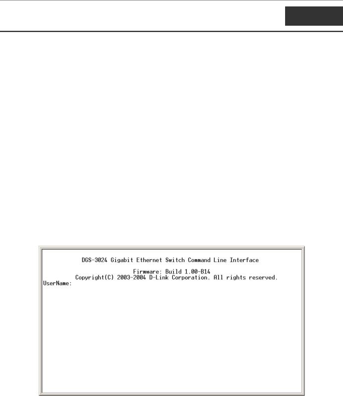
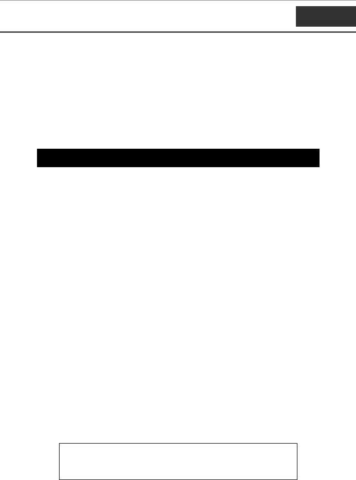
With the serial port properly connected to a management computer, the following screen should be visible. If this screen does not appear, try pressing Ctrl+r to refresh the console screen.
Figure 1-1. Initial CLI screen
There is no initial username or password. Just press the Enter key twice to display the CLI input cursor − DGS-3024:4#. This is the command line where all commands are input.
1
DGS-3024 Layer 2 Switch CLI Reference Manual
Setting the Switch’s IP Address
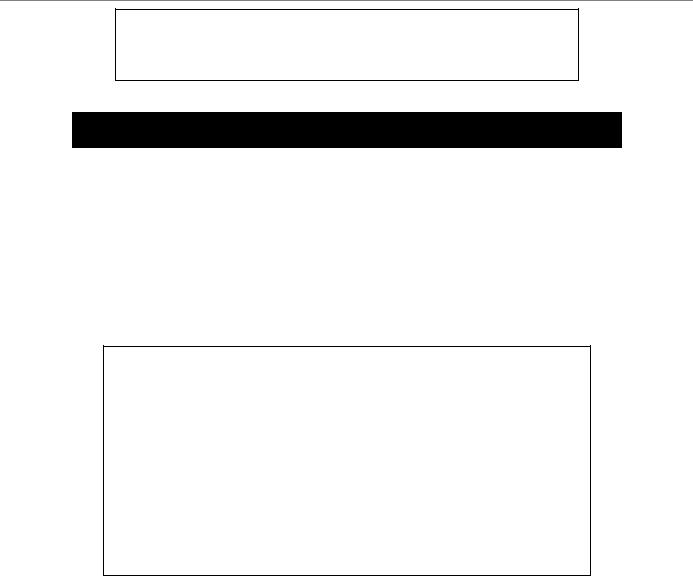
Each switch must be assigned its own IP Address, which is used for communication with an SNMP network manager or other TCP/IP application (for example BOOTP, TFTP). The Switch’s default IP address is 10.90.90.90. You can change the default Switch IP address to meet the specification of your networking address scheme.
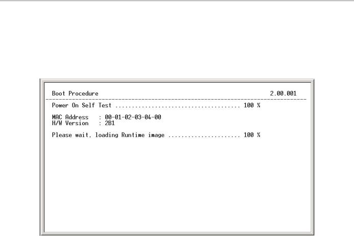
The Switch is also assigned a unique MAC address by the factory. This MAC address cannot be changed, and can be found on the initial boot console screen – shown below.
Figure 1-2. Boot Screen
The Switch’s MAC address can also be found in the Web management program on the Switch Information (Basic Settings) window on the Configuration menu.
The IP address for the Switch must be set before it can be managed with the Web-based manager. The Switch IP address can be automatically set using BOOTP or DHCP protocols, in which case the actual address assigned to the Switch must be known.
The IP address may be set using the Command Line Interface (CLI) over the console serial port as follows:
1.Starting at the command line prompt, enter the commands config ipif System ipaddress xxx.xxx.xxx.xxx/yyy.yyy.yyy.yyy. Where the x’s represent the IP address to be assigned to the IP interface named System and the y’s represent the corresponding subnet mask.
2.Alternatively, you can enter config ipif System ipaddress xxx.xxx.xxx.xxx/z. Where the x’s represent the IP address to be assigned to the IP interface named System and the z represents the corresponding number of subnets in CIDR notation.
The IP interface named System on the Switch can be assigned an IP address and subnet mask which can then be used to connect a management station to the Switch’s Telnet or Web-based management agent.
2
DGS-3024 Layer 2 Switch CLI Reference Manual
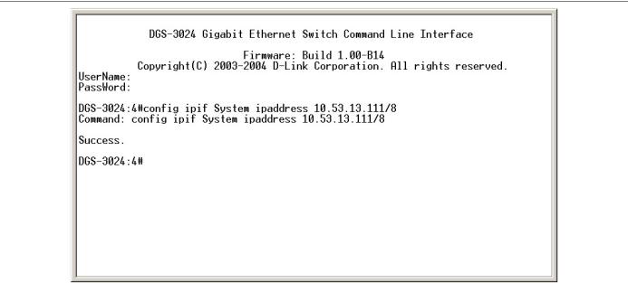
Figure 1-3. Assigning an IP Address
In the above example, the Switch was assigned an IP address of 10.53.13.111 with a subnet mask of 255.0.0.0 (8 in CIDR from). The system message Success indicates that the command was executed successfully. The Switch can now be configured and managed via Telnet and the CLI or via the Web-based management agent using the above IP address to connect to the Switch.
3
DGS-3024 Layer 2 Switch CLI Reference Manual
2
USING THE CONSOLE CLI
The DGS-3024 supports a console management interface that allows the user to connect to the Switch’s management agent via a serial port and a terminal or a computer running a terminal emulation program. The console can also be used over the network using the TCP/IP Telnet protocol. The console program can be used to configure the Switch to use an SNMP-based network management software over the network.
This chapter describes how to use the console interface to access the Switch, change its settings, and monitor its operation.
Note: Switch configuration settings are saved to non-volatile RAM using the save command. The current configuration will then be retained in the Switch’s NV-RAM, and reloaded when the Switch is rebooted. If the Switch is rebooted without using the save command, the last configuration saved to NV-RAM will be loaded.
Connecting to the Switch
The console interface is used by connecting the Switch to a VT100-compatible terminal or a computer running an ordinary terminal emulator program (e.g., the HyperTerminal program included with the Windows operating system) using an RS-232C serial cable. Your terminal parameters will need to be set to:
•VT-100 compatible
•9,600 baud
•8 data bits
•No parity
•One stop bit
•No flow control
You can also access the same functions over a Telnet interface. Once you have set an IP address for your Switch, you can use a Telnet program (in VT-100 compatible terminal mode) to access and control the Switch. All of the screens are identical, whether accessed from the console port or from a Telnet interface.
After the Switch reboots and you have logged in, the console looks like this:
4

DGS-3024 Layer 2 Switch CLI Reference Manual
Figure 2-1. Console Screen after login
Commands are entered at the command prompt, DGS-3024:4#.
There are a number of helpful features included in the CLI. Entering the ? command will display a list of all of the top-level commands.
Figure 2-2. The ? Command
The dir command has the same function as the ? command.
When you enter a command without its required parameters, the CLI will prompt you with a Next possible completions: message.
5
DGS-3024 Layer 2 Switch CLI Reference Manual
Figure 2-3. Example Command Parameter Help
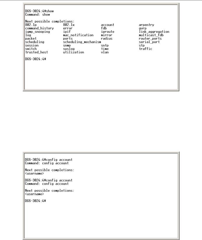
In this case, the command show was entered without a parameter. The CLI will then prompt you to enter the next possible completions with the message, Next possible completions:. Every command in the CLI has this feature, and complex commands have several layers of parameter prompting.
In addition, after typing any given command plus one space, you can see all of the next possible sub-commands, in sequential order, by repeatedly pressing the Tab key.
To re-enter a previously entered command at the command prompt, press the up arrow cursor key. The previous command will appear at the command prompt.
Figure 2-4. Using the Up Arrow to Re-enter a Command
In the above example, the command config account was entered without the required parameter <username>, the CLI returned the Next possible completions: <username> prompt. The up arrow cursor control key was pressed to re-enter the previous command (config account) at the command prompt. Now the appropriate user name can be entered and the config account command re-executed.
6
DGS-3024 Layer 2 Switch CLI Reference Manual
All commands in the CLI function in this way. In addition, the syntax of the help prompts are the same as presented in this manual − angle brackets < > indicate a numerical value or character string, braces { } indicate optional parameters or a choice of parameters, and brackets [ ] indicate required parameters.
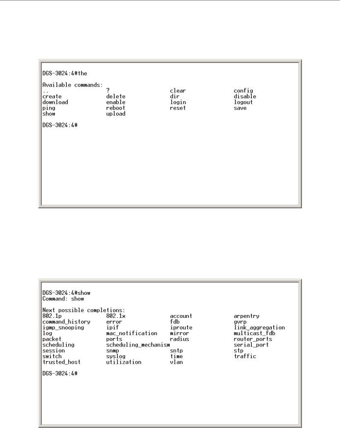
If a command is entered that is unrecognized by the CLI, the top-level commands will be displayed under the Available commands: prompt.
Figure 2-5. The Next Available Commands Prompt
The top-level commands consist of commands such as show or config. Most of these commands require one or more parameters to narrow the top-level command. This is equivalent to show what? or config what? Where the what? is the next parameter.
For example, if you enter the show command with no additional parameters, the CLI will then display all of the possible next parameters.
Figure 2-6. Next possible completions: show command
7

DGS-3024 Layer 2 Switch CLI Reference Manual
In the above example, all of the possible next parameters for the show command are displayed. At the next command prompt, the up arrow was used to re-enter the show command, followed by the account parameter. The CLI then displays the user accounts configured on the Switch.
8
DGS-3024 Layer 2 Switch CLI Reference Manual
3
COMMAND SYNTAX
The following symbols are used to describe how command entries are made and values and arguments are specified in this manual. The online help contained in the CLI and available through the console interface uses the same syntax.
Note: All commands are case-sensitive. Be sure to disable Caps Lock or any other unwanted function that changes text case.
<angle brackets>
Purpose |
Encloses a variable or value that must be specified. |
|
|
Syntax |
create ipif <ipif_name> vlan <vlan_name 32> ipaddress |
|
<network_address> |
Description |
In the above syntax example, you must supply an IP interface name in the |
|
<ipif_name> space, a VLAN name in the <vlan_name 32> space, and the |
|
network address in the <network_address> space. Do not type the angle |
|
brackets. |
|
|
Example |
create ipif Engineering vlan Design ipaddress 10.24.22.5/255.0.0.0 |
Command |
|
[square brackets]
Purpose |
Encloses a required value or set of required arguments. One value or |
|
argument can be specified. |
|
|
Syntax |
create account [admin | user] |
|
|
Description |
In the above syntax example, you must specify either an admin or a user |
|
level account to be created. Do not type the square brackets. |
Example |
create account admin |
Command |
|
| vertical bar
Purpose |
Separates two or more mutually exclusive items in a list, one of which must |
|
be entered. |
|
|
Syntax |
show snmp [community | detail] |
|
|
Description |
In the above syntax example, you must specify either community, or |
|
detail. Do not type the vertical bar. |
Example |
show snmp community |
Command |
|
9

DGS-3024 Layer 2 Switch CLI Reference Manual
{braces}
Purpose |
Encloses an optional value or set of optional arguments. |
|
|
Syntax |
reset {[config | system]} |
|
|
Description |
In the above syntax example, you have the option to specify config or |
|
system. It is not necessary to specify either optional value, however the |
|
effect of the system reset is dependent on which, if any, value is specified. |
|
Therefore, with this example there are three possible outcomes of |
|
performing a system reset. See the chapter Basic Commands for more |
|
details about the reset command. |
Example |
reset config |
command |
|
Line Editing Key Usage
Delete |
Deletes the character under the cursor and then shifts the remaining |
|
characters in the line to the left. |
|
|
Backspace |
Deletes the character to the left of the cursor and shifts the remaining |
|
characters in the line to the left. |
Left Arrow |
Moves the cursor to the left. |
|
|
Right Arrow |
Moves the cursor to the right. |
|
|
Up Arrow |
Repeat the previously entered command. Each time the up arrow is |
|
pressed, the command previous to that displayed appears. This way it is |
|
possible to review the command history for the current session. Use the |
|
down arrow to progress sequentially forward through the command history |
|
list. |
|
|
Down Arrow |
The down arrow will display the next command in the command history |
|
entered in the current session. This displays each command sequentially as |
|
it was entered. Use the up arrow to review previous commands. |
Tab |
Shifts the cursor to the next field to the left. |
|
|
Multiple Page Display Control Keys
Space |
Displays the next page. |
|
|
CTRL+c |
Stops the display of remaining pages when multiple pages are to be |
|
displayed. |
|
|
ESC |
Stops the display of remaining pages when multiple pages are to be |
|
displayed. |
n |
Displays the next page. |
|
|
p |
Displays the previous page. |
|
|
q |
Stops the display of remaining pages when multiple pages are to be |
|
displayed. |
|
|
r |
Refreshes the pages currently displayed. |
|
|
a |
Displays the remaining pages without pausing between pages. |
|
|
Enter |
Displays the next line or table entry. |
|
|
10

DGS-3024 Layer 2 Switch CLI Reference Manual
4
BASIC SWITCH COMMANDS
The basic switch commands in the Command Line Interface (CLI) are listed (along with the appropriate parameters) in the following table.
Command |
Parameters |
create account |
[admin | user] <username 15> |
|
|
config account |
<username> |
|
|
show account |
|
|
|
show session |
|
|
|
show switch |
|
|
|
show serial_port |
|
|
|
config serial_port |
{baud_rate [9600 | 19200 | 38400 | 115200] auto_logout [never | |
|
2_minutes | 5_minutes| 10_minutes | 15_minutes]} |
|
|
enable clipaging |
|
|
|
disable clipaging |
|
|
|
enable telnet |
<tcp_port_number 1-65535> |
|
|
disable telnet |
|
|
|
enable web |
<tcp_port_number 1-65535> |
|
|
disable web |
|
|
|
save |
|
|
|
reboot |
|
|
|
reset |
{[config | system]} |
|
|
login |
|
|
|
logout |
|
|
|
ping |
<ipaddr> {times <value 1-255>} {timeout <sec 1-99>} |
|
|
Each command is listed, in detail, in the following sections.
create account
Purpose |
Used to create user accounts. |
Syntax |
create [admin | user] <username 15> |
Description |
The create account command is used to create user accounts that |
|
consist of a username of 1 to 15 characters and a password of 0 to |
|
15 characters. Up to 8 user accounts can be created. |
Parameters |
admin <username> |
|
user <username> |
Restrictions |
Only Administrator-level users can issue this command. |
|
Usernames can be between 1 and 15 characters. |
|
|
11

DGS-3024 Layer 2 Switch CLI Reference Manual
create account
Passwords can be between 0 and 15 characters.
Example usage:
To create an administrator-level user account with the username “dlink”.
DGS-3024:4#create account admin dlink
Command: create account admin dlink
Enter a case-sensitive new password:****
Enter the new password again for confirmation:****
Success.
DGS-3024:4#
config account
Purpose |
Used to configure user accounts. |
Syntax |
config account <username> |
Description |
The config account command configures a user account that has |
|
been created using the create account command. |
Parameters |
<username> |
Restrictions |
Only Administrator-level users can issue this command. |
|
Usernames can be between 1 and 15 characters. |
|
Passwords can be between 0 and 15 characters. |
|
|
Example usage:
To configure the user password of “dlink” account:
DGS-3024:4#config account dlink
Command: config account dlink
Enter a old password:****
Enter a case-sensitive new password:****
Enter the new password again for confirmation:****
Success.
DGS-3024:4#
show account
Purpose |
Used to display user accounts. |
Syntax |
show account |
|
|
12

DGS-3024 Layer 2 Switch CLI Reference Manual
show account
Description |
Displays all user accounts created on the Switch. Up to 8 user |
|
accounts can exist on the Switch at one time. |
Parameters |
None. |
Restrictions |
None. |
|
|
Example usage:
To display the accounts that have been created:
DGS-3024:4#show account
Command: show account
|
Current Accounts: |
||
|
Username |
Access Level |
|
--------------- |
------------ |
|
|
|
dlink |
Admin |
|
|
Total Entries: 1 |
||
|
DGS-3024:4# |
||
|
|
|
|
|
|||
delete account |
|||
|
|
||
Purpose |
Used to delete an existing user account. |
||
Syntax |
delete account <username> |
||
Description |
The delete account command deletes a user account that has been |
||
|
|
created using the create account command. |
|
Parameters |
<username> |
||
Restrictions |
Only Administrator-level users can issue this command. |
||
|
|
|
|
Example usage:
To delete the user account “System”:
DGS-3024:4#delete account System
Command: delete account System
Are you sure to delete the last administrator account?(y/n)
Success.
DGS-3024:4#
13

DGS-3024 Layer 2 Switch CLI Reference Manual
show session
|
Purpose |
Used to display a list of currently logged-in users. |
||||||
|
Syntax |
show session |
|
|
|
|
||
|
Description |
This command displays a list of all the users that are logged-in at |
||||||
|
|
|
the time the command is issued. |
|
|
|
||
|
Parameters |
None. |
|
|
|
|
|
|
|
Restrictions |
None. |
|
|
|
|
|
|
|
|
|
|
|
|
|
|
|
Example usage: |
|
|
|
|
|
|
||
To display the way that the users logged in: |
|
|
|
|
||||
|
|
|
|
|
|
|
||
|
|
DGS-3024:4#show session |
|
|
|
|
||
|
|
Command: show session |
|
|
|
|
||
|
|
ID Login Time |
Live Time |
From |
Level Name |
|
||
|
-- --------------------------- |
--------------- |
-------------- |
------- |
------------------- |
|
||
|
*8 2204/01/26 3:36:27 |
0:0:20.260 |
Serial Port 4 |
Anonymous |
|
|||
|
|
CTRL+C ESC q Quit SPACE n Next Page p Previous Page r Refresh |
|
|||||
|
|
|
|
|
|
|
|
|
show switch
|
Purpose |
Used to display information about the Switch. |
|
Syntax |
show switch |
|
Description |
This command displays information about the Switch. |
|
Parameters |
None. |
|
Restrictions |
None. |
|
|
|
Example usage: |
|
|
To display the Switch information:
DGS-3024:4#show switch
Command: show switch
Device Type |
: DGS-3024 Gigabit-Ethernet Switch |
MAC Address |
: DA-10-21-00-00-01 |
IP Address |
: 10.41.44.22 (Manual) |
VLAN Name |
: default |
Subnet Mask |
: 255.0.0.0 |
Default Gateway |
: 0.0.0.0 |
Boot PROM Version : Build 2.00.004 |
|
Firmware Version |
: Build 1.00-B14 |
Hardware Version |
: 0A1 |
System Name |
: DGS-3024_#3 |
System Location |
: 7th_flr_east_cabinet |
System Contact |
: Julius_Erving_212-555-6666 |
Spanning Tree |
: Disabled |
GVRP |
: Disabled |
14

DGS-3024 Layer 2 Switch CLI Reference Manual
IGMP Snooping |
: Disabled |
TELNET |
: Enabled (TCP 23) |
WEB |
: Enabled (TCP 80) |
RMON |
: Enabled |
DGS-3024:4# |
|
|
|
show serial_port
Purpose |
Used to display the current serial port settings. |
Syntax |
show serial_port |
Description |
This command displays the current serial port settings. |
Parameters |
None. |
Restrictions |
None. |
|
|
Example usage:
To display the serial port setting:
DGS-3024:4#show serial_port
Command: show serial_port
Baud Rate |
: 9600 |
Data Bits |
: 8 |
Parity Bits |
: None |
Stop Bits |
: 1 |
Auto-Logout |
: 10 mins |
DGS-3024:4#
config serial_port
Purpose Used to configure the serial port.
Syntax config serial_port {baud_rate [9600 | 19200 | 38400 | 115200] | auto_logout [never | 2_minutes | 5_minutes | 10_minutes | 15_minutes]}
Description This command is used to configure the serial port’s baud rate and auto logout settings.
Parameters baud rate [9600 | 19200 | 38400 | 115200] − The serial bit rate that will be used to communicate with the management host.
auto_logout - This parameter will allow the user to choose the time the Switch’s serial port will be idle before automatically logging out. The user may choose one of the following.
never − No time limit on the length of time the console can be open with no user input.
2_minutes − The console will log out the current user if there is no user input for 2 minutes.
15

DGS-3024 Layer 2 Switch CLI Reference Manual
config serial_port
5_minutes − The console will log out the current user if there is no user input for 5 minutes.
10_minutes − The console will log out the current user if there is no user input for 10 minutes.
15_minutes − The console will log out the current user if there is no user input for 15 minutes.
Restrictions Only administrator-level users can issue this command.
Example usage:
To configure the baud rate:
DGS-3024:4#config serial_port baud_rate 9600
Command: config serial_port baud_rate 9600
Success.
DGS-3024:4#
enable clipaging
Purpose |
Used to pause the scrolling of the console screen when the show |
|
command displays more than one page. |
Syntax |
enable clipaging |
Description |
This command is used when issuing a command which causes the |
|
console screen to rapidly scroll through several pages. This |
|
command will cause the console to pause at the end of each page. |
|
The default setting is enabled. |
Parameters |
None. |
Restrictions |
Only administrator-level users can issue this command. |
|
|
Example usage:
To enable pausing of the screen display when the show command output reaches the end of the page:
DGS-3024:4#enable clipaging
Command: enable clipaging
Success.
DGS-3024:4#
16

DGS-3024 Layer 2 Switch CLI Reference Manual
disable clipaging
Purpose |
Used to disable the pausing of the console screen scrolling at the |
|
end of each page when the command displays more than one |
|
screen of information. |
Syntax |
disable clipaging |
Description |
This command is used to disable the pausing of the console screen |
|
at the end of each page when the command would display more |
|
than one screen of information. |
Parameters |
None. |
Restrictions |
Only administrator-level users can issue this command. |
|
|
Example usage:
To disable pausing of the screen display when show command output reaches the end of the page:
DGS-3024:4#disable clipaging
Command: disable clipaging
Success.
DGS-3024:4#
enable telnet
Purpose |
Used to enable communication with and management of the Switch |
|
using the Telnet protocol. |
Syntax |
enable telnet <tcp_port_number 1-65535> |
Description |
This command is used to enable the Telnet protocol on the Switch. |
|
The user can specify the TCP or UDP port number the Switch will |
|
use to listen for Telnet requests. |
Parameters |
<tcp_port_number 1-65535> − The TCP port number. TCP ports |
|
are numbered between 1 and 65535. The “well-known” TCP port |
|
for the Telnet protocol is 23. |
Restrictions |
Only administrator-level users can issue this command. |
|
|
Example usage:
To enable Telnet and configure port number:
DGS-3024:4#enable telnet 23
Command: enable telnet 23
Success.
DGS-3024:4#
17

DGS-3024 Layer 2 Switch CLI Reference Manual
disable telnet
Purpose |
Used to disable the Telnet protocol on the Switch. |
Syntax |
disable telnet |
Description |
This command is used to disable the Telnet protocol on the Switch. |
Parameters |
None. |
Restrictions |
Only administrator-level users can issue this command. |
|
|
Example usage:
To disable the Telnet protocol on the Switch:
DGS-3024:4#disable telnet
Command: disable telnet
Success.
DGS-3024:4#
enable web
Purpose |
Used to enable the HTTP-based management software on the |
|
Switch. |
Syntax |
enable web <tcp_port_number 1-65535> |
Description |
This command is used to enable the Web-based management |
|
software on the Switch. The user can specify the TCP port number |
|
the Switch will use to listen for Telnet requests. |
Parameters |
<tcp_port_number 1-65535> − The TCP port number. TCP ports |
|
are numbered between 1 and 65535. The “well-known” port for the |
|
Web-based management software is 80. |
Restrictions |
Only administrator-level users can issue this command. |
|
|
Example usage:
To enable HTTP and configure port number:
DGS-3024:4#enable web 80
Command: enable web 80
Success.
DGS-3024:4#
18
DGS-3024 Layer 2 Switch CLI Reference Manual
disable web
Purpose |
Used to disable the HTTP-based management software on the |
|
Switch. |
Syntax |
disable web |
Description |
This command disables the Web-based management software on |
|
the Switch. |
Parameters |
None. |
Restrictions |
Only administrator-level users can issue this command. |
|
|
Example usage:
To disable HTTP:
DGS-3024:4#disable web
Command: disable web
Success.
DGS-3024:4#
save
Purpose |
Used to save changes in the Switch’s configuration to non-volatile |
|
RAM. |
Syntax |
save |
Description |
This command is used to enter the current switch configuration into |
|
non-volatile RAM. The saved switch configuration will be loaded into |
|
the Switch’s memory each time the Switch is restarted. |
Parameters |
None. |
Restrictions |
Only administrator-level users can issue this command. |
|
|
Example usage:
To save the Switch’s current configuration to non-volatile RAM:
DGS-3024:4#save
Command: save
Saving all configurations to NV-RAM... Done.
DGS-3024:4#
19
DGS-3024 Layer 2 Switch CLI Reference Manual
reboot
Purpose |
Used to restart the Switch. |
Syntax |
reboot |
Description |
This command is used to restart the Switch. |
Parameters |
None. |
Restrictions |
None. |
|
|
Example usage:
To restart the Switch:
DGS-3024:4#reboot
Command: reboot
Are you sure want to proceed with the system reboot? (y/n)
reset
Purpose |
Used to reset the Switch to the factory default settings. |
Syntax |
reset {[config | system]} |
Description |
This command is used to restore the Switch’s configuration to the |
|
default settings assigned from the factory. |
Parameters |
config − If the keyword ‘config’ is specified, all of the factory default |
|
settings are restored on the Switch including the IP address, user |
|
accounts, and the Switch history log. The Switch will not save or |
|
reboot. |
|
system − If the keyword ‘system’ is specified all of the factory default |
|
settings are restored on the Switch. The Switch will save and reboot |
|
after the settings are changed to default. Rebooting will clear all |
|
entries in the Forwarding Data Base. |
|
If no parameter is specified, the Switch’s current IP address, user |
|
accounts, and the Switch history log are not changed. All other |
|
parameters are restored to the factory default settings. The Switch |
|
will not save or reboot. |
Restrictions |
Only administrator-level users can issue this command. |
|
|
Example usage:
To restore all of the Switch’s parameters to their default values:
DGS-3024:4#reset config
Command: reset config
Success.
DGS-3024:4#
20
DGS-3024 Layer 2 Switch CLI Reference Manual
login
Purpose |
Used to log in a user to the Switch’s console. |
Syntax |
login |
Description |
This command is used to initiate the login procedure. The user will be |
|
prompted for his Username and Password. |
Parameters |
None. |
Restrictions |
None. |
|
|
Example usage:
To initiate the login procedure:
DGS-3024:4#login
Command: login
UserName:
logout
Purpose |
Used to log out a user from the Switch’s console. |
Syntax |
logout |
Description |
This command terminates the current user’s session on the Switch’s |
|
console. |
Parameters |
None. |
Restrictions |
None. |
|
|
Example usage:
To terminate the current user’s console session:
|
DGS-3024:4#logout |
|
|
|
|
|
|
|
ping |
|
|
|
|
|
Purpose |
Used to test the connectivity between network devices. |
|
Syntax |
ping <ipaddr> {times <value 1-255>} {timeout <sec 1-99>} |
|
Description |
The ping command sends Internet Control Message Protocol |
|
|
(ICMP) echo messages to a remote IP address. The remote IP |
|
|
address will then “echo” or return the message. This is used to |
|
|
confirm connectivity between the Switch and the remote device. |
|
Parameters |
<ipaddr> - Specifies the IP address of the host. |
|
|
times <value 1-255> - The number of individual ICMP echo |
|
|
messages to be sent. The maximum value is 255. The default is |
|
|
0. |
|
|
timeout <sec 1-99> - Defines the time-out period while waiting for |
|
|
a response from the remote device. A value of 1 to 99 seconds |
|
|
can be specified. The default is 1 second. |
|
21
DGS-3024 Layer 2 Switch CLI Reference Manual
ping
Pinging an IP address without the times parameter will ping the target device an infinite amount of times.
Restrictions None.
Example usage:
To ping the IP address 10.48.74.121 four times:
DGS-3024:4#ping 10.48.74.121 times 4
Command: ping 10.48.74.121
Reply from 10.48.74.121, time<10ms
Reply from 10.48.74.121, time<10ms
Reply from 10.48.74.121, time<10ms
Reply from 10.48.74.121, time<10ms
Ping statistics for 10.48.74.121
Packets: Sent =4, Received =4, Lost =0
DGS-3024:4#
22
DGS-3024 Layer 2 Switch CLI Reference Manual
5
SWITCH PORT COMMANDS
The switch port commands in the Command Line Interface (CLI) are listed (along with the appropriate parameters) in the following table.
Command |
Parameters |
config ports |
[<portlist> | all] {speed [auto | 10_half | 10_full | 100_half | 100_full | |
|
1000_full] | flow_control [enable | disable] | learning [enable | |
|
disable] | state [enable | disable]} |
|
|
show ports |
{<portlist>} |
|
|
Each command is listed, in detail, in the following sections.
config ports
Purpose |
Used to configure the Switch’s Ethernet port settings. |
Syntax |
config ports [<portlist> | all] {speed [auto | 10_half | 10_full | 100_half |
|
| 100_full | 1000_full] | flow_control [enable | disable] | learning |
|
[enable | disable] | state [enable | disable]} |
Description |
This command allows for the configuration of the Switch’s Ethernet ports. |
|
Only the ports listed in the <portlist> will be affected. |
Parameters |
<portlist> − Specifies a range of ports to be configured. |
|
all − Configure all ports on the Switch. |
|
speed – Allows the user to set the speed of a port or range of ports, with |
|
the addition of one of the following: |
|
auto − Enables auto-negotiation for the specified range of ports. |
|
[10 | 100 | 1000] − Configures the speed in Mbps for the specified |
|
range of ports. Gigabit ports are statically set to 1000 and cannot be |
|
set to slower speeds. |
|
[half | full] − Configures the specified range of ports as either full- |
|
or half-duplex. |
|
flow_control [enable | disable] – Enable or disable flow control for the |
|
specified ports. |
|
learning [enable | disable] − Enables or disables the MAC address |
|
learning on the specified range of ports. |
|
state [enable | disable] − Enables or disables the specified range of ports. |
Restrictions |
Only administrator-level users can issue this command. |
|
|
Example usage:
To configure the speed of ports 1-3 to be 10 Mbps, full duplex, learning and state enabled:
DGS-3024:4#config ports 1-3 speed 10_full learning enable state enable
Command: config ports 1-3 speed 10_full learning enable state enable
23
DGS-3024 Layer 2 Switch CLI Reference Manual
Success.
DGS-3024:4#
show ports
Purpose |
Used to display the current configuration of a range of ports. |
Syntax |
show ports {<portlist>} |
Description |
This command is used to display the current configuration of a range |
|
of ports. |
Parameters |
<portlist> − Specifies a port or range of ports to be displayed. |
Restrictions |
None. |
|
|
Example usage:
To display the configuration of ports 1-5 on the Switch:
DGS-3024:4#show ports 1-5
Command: show ports 1-5
Port |
Port |
Settings |
Connection |
Address |
|
State |
Speed/Duplex/FlowCtrl |
Speed/Duplex/FlowCtrl |
Learning |
--- |
-------- |
--------------------- |
--------------------- |
-------- |
1 |
Enabled |
Auto/Enabled |
Link Down |
Enabled |
2 |
Enabled |
Auto/Enabled |
Link Down |
Enabled |
3 |
Enabled |
Auto/Enabled |
Link Down |
Enabled |
4 |
Enabled |
Auto/Enabled |
Link Down |
Enabled |
5 |
Enabled |
Auto/Enabled |
Link Down |
Enabled |
CTRL+C ESC q Quit SPACE n Next Page p Previous Page r Refresh
24

DGS-3024 Layer 2 Switch CLI Reference Manual
6
NETWORK MANAGEMENT (SNMP) COMMANDS
The network management commands in the Command Line Interface (CLI) are listed (along with the appropriate parameters) in the following table.
The DGS-3024 supports the Simple Network Management Protocol (SNMP) versions 1, 2c, and 3. The user may specify which version of the SNMP to use to monitor and control the Switch. The three versions of SNMP vary in the level of security provided between the management station and the network device. The following table lists the security features of the three SNMP versions:
SNMP |
Authentication Method |
Description |
Version |
|
|
|
|
|
v1 |
Community String |
Community String is used for authentication − NoAuthNoPriv |
|
|
|
v2c |
Community String |
Community String is used for authentication − NoAuthNoPriv |
|
|
|
v3 |
Username |
Username is used for authentication − NoAuthNoPriv |
|
|
|
v3 |
MD5 or SHA |
Authentication is based on the HMAC-MD5 or HMAC-SHA algorithms |
|
|
− AuthNoPriv |
|
|
|
v3 |
MD5 DES or SHA DES |
Authentication is based on the HMAC-MD5 or HMAC-SHA algorithms |
|
|
− AuthPriv. |
|
|
DES 32-bit encryption is added based on the CBC-DES (DES-32) |
|
|
standard |
|
|
|
Command |
Parameters |
create snmp user |
<username 32> <groupname 32> {encrypted [by_password |
|
auth [md5 <auth_password 8-16> | sha <auth_password 8- |
|
20>] priv [none | des <priv_password 8-16>] | by_key auth |
|
[md5 <auth_key 32-32>| sha<auth_key 40-40>] priv [none | |
|
des <priv_key 32-32>]]} |
|
|
delete snmp user |
<username 32> |
|
|
show snmp user |
|
|
|
create snmp view |
<view_name 32> <oid> view_type [included | excluded] |
|
|
delete snmp view |
<view_name 32> [all | oid] |
|
|
show snmp view |
{<view_name 32>} |
|
|
create snmp community |
<community_string 32> view <view_name 32> [read_only | |
|
read_write] |
delete snmp community |
<community_string 32> |
|
|
show snmp community |
{<community_string 32>} |
|
|
config snmp engineID |
<snmp_engineID> |
|
|
show snmp engineID |
|
|
|
create snmp group |
<groupname 32> [v1 | v2c | v3 [noauth_nopriv | auth_nopriv | |
|
|
25

DGS-3024 Layer 2 Switch CLI Reference Manual
Command |
Parameters |
|
auth_priv]] {read_view <view_name 32> | write_view |
|
<view_name 32> | notify_view <view_name 32>} |
delete snmp group |
<groupname 32> |
|
|
show snmp groups |
|
|
|
create snmp host |
<ipaddr> [v1 | v2c | v3 [noauth_nopriv | auth_nopriv | |
|
auth_priv]] <auth_string 32> |
|
|
delete snmp host |
<ipaddr> |
|
|
show snmp host |
{<ipaddr>} |
|
|
enable rmon |
|
|
|
disable rmon |
|
|
|
create trusted_host |
<ipaddr> |
|
|
delete trusted_host |
<ipaddr> |
|
|
show trusted_host |
<ipaddr> |
|
|
enable snmp traps |
|
|
|
disable snmp traps |
|
|
|
enable snmp |
|
authenticate traps |
|
|
|
disable snmp |
|
authenticate traps |
|
show snmp traps |
|
|
|
config snmp |
<sw_contact> |
system_contact |
|
config snmp |
<sw_location> |
system_location |
|
config snmp |
<sw_name> |
system_name |
|
|
|
Each command is listed, in detail, in the following sections.
create snmp user
Purpose |
Used to create a new SNMP user and adds the user to an SNMP |
|
group that is also created by this command. |
Syntax |
create snmp user <username 32> <groupname 32> {encrypted |
|
[by_password auth [md5 <auth_password 8-16> | sha |
|
<auth_password 8-20>] priv [none | des <priv_password 8-16>] | |
|
by_key auth [md5 <auth_key 32-32>| sha <auth_key 40-40>] priv |
|
[none | des <priv_key 32-32>]]} |
Description |
The create snmp user command creates a new SNMP user and |
|
adds the user to an SNMP group that is also created by this |
|
command. |
Parameters |
<username 32> − An alphanumeric name of up to 32 characters that |
|
will identify the new SNMP user. |
|
<groupname 32> − An alphanumeric name of up to 32 characters |
26

DGS-3024 Layer 2 Switch CLI Reference Manual
create snmp user
that will identify the SNMP group the new SNMP user will be associated with.
encrypted – Allows the user to choose a type of authorization for authentication using SNMP. The user may choose:
•by_password – Requires the SNMP user to enter a password for authentication and privacy. The password is defined by specifying the auth_password below. This method is recommended.
•by_key – Requires the SNMP user to enter a encryption key for authentication and privacy. The key is defined by specifying the key in hex form below. This method is not recommended.
auth - The user may also choose the type of authentication algorithms used to authenticate the snmp user. The choices are:
•md5 − Specifies that the HMAC-MD5-96 authentication level will be used. md5 may be utilized by entering one of the following:
<auth password 8-16> - An alphanumeric sting of between 8 and 16 characters that will be used to authorize the agent to receive packets for the host.
<auth_key 32-32> - Enter an alphanumeric sting of exactly 32 characters, in hex form, to define the key that will be used to authorize the agent to receive packets for the host.
•sha − Specifies that the HMAC-SHA-96 authentication level will be used.
<auth password 8-20> - An alphanumeric sting of between 8 and 20 characters that will be used to authorize the agent to receive packets for the host.
<auth_key 40-40> - An alphanumeric sting of exactly 40 characters, in hex form, to define the key that will be used to authorize the agent to receive packets for the host.
priv – Adding the priv (privacy) parameter will allow for encryption in addition to the authentication algorithm for higher security. The user may choose:
•des – Adding this parameter will allow for a 56-bit encryption to be added using the DES-56 standard using:
<priv_password 8-16> - An alphanumeric string of between 8 and 16 characters that will be used to encrypt the contents of messages the host sends to the agent.
<priv_key 32-32> - An alphanumeric key string of exactly 32 characters, in hex form, that will be used to encrypt the contents of messages the host sends to
27

DGS-3024 Layer 2 Switch CLI Reference Manual
create snmp user
|
the agent. |
|
none – Adding this parameter will add no encryption. |
Restrictions |
Only administrator-level users can issue this command. |
|
|
Example usage:
To create an SNMP user on the Switch:
DGS-3024:4#create snmp user dlink default encrypted by_password auth md5 auth_password priv none
Command: create snmp user dlink default encrypted by_password auth md5 auth_password priv none
Success.
DGS-3024:4#
delete snmp user
Purpose |
Used to remove an SNMP user from an SNMP group and also to |
|
delete the associated SNMP group. |
Syntax |
delete snmp user <username 32> |
Description |
The delete snmp user command removes an SNMP user from its |
|
SNMP group and then deletes the associated SNMP group. |
Parameters |
<username 32> − An alphanumeric string of up to 32 characters that |
|
identifies the SNMP user that will be deleted. |
Restrictions |
Only administrator-level users can issue this command. |
|
|
Example usage:
To delete a previously entered SNMP user on the Switch:
DGS-3024:4#delete snmp user dlink
Command: delete snmp user dlink
Success.
DGS-3024:4#
28
Loading...