


DES-1228P
24-Port 10/100Mbps PoE Web Smart Switch with 4-Port 10/100/1000Base-T and 2-Port Combo SFP
User Manual
V1.20

TABLE OF CONTENTS |
|
About This Guide................................................................................. |
1 |
Purpose ............................................................................................ |
1 |
Terms/Usage .................................................................................... |
1 |
Introduction.......................................................................................... |
2 |
Gigabit Ethernet Technology ........................................................... |
2 |
Fast Ethernet Technology ................................................................ |
3 |
Switching Technology ..................................................................... |
4 |
Power over Ethernet (PoE) .............................................................. |
4 |
Features............................................................................................ |
5 |
Technical Specifications .................................................................. |
6 |
Unpacking and Installation ................................................................ |
11 |
Unpacking...................................................................................... |
11 |
Installation ..................................................................................... |
11 |
Rack Mounting........................................................................... |
12 |
Connecting Network Cables ...................................................... |
13 |
AC Power................................................................................... |
14 |
Identifying External Components ...................................................... |
15 |
Front Panel..................................................................................... |
15 |
Rear Panel...................................................................................... |
17 |
Understanding LED Indicators ...................................................... |
17 |
Power and System LEDs ............................................................... |
18 |
Configuration ..................................................................................... |
22 |
Supported web browsers ................................................................ |
22 |
i

Installing the SmartConsole Utility................................................ |
22 |
SmartConsole Utility Features ....................................................... |
23 |
Menu Toolbar............................................................................. |
23 |
Discovery List............................................................................ |
25 |
Monitor List ............................................................................... |
26 |
Device Setting............................................................................ |
28 |
Web-based Utility .......................................................................... |
30 |
Login.......................................................................................... |
30 |
Tool Menu.................................................................................. |
32 |
Setup Menu .................................................................................... |
33 |
System > System Setting ........................................................... |
34 |
System > Trap Setting................................................................ |
35 |
System > Port Setting................................................................. |
37 |
System > SNMP Setting ............................................................ |
38 |
System > Password Access Control........................................... |
40 |
Configuration > 802.1Q VLAN ................................................. |
40 |
Configuration > Trunking .......................................................... |
43 |
Configuration > IGMP Snooping............................................... |
43 |
Configuration > 802.1D Spanning Tree..................................... |
47 |
Configuration > Port Mirroring.................................................. |
49 |
Configuration > LLDP............................................................... |
50 |
Power over Ethernet (PoE) > PoE Port Setting.......................... |
50 |
Power over Ethernet (PoE) > PoE System Setting..................... |
52 |
QoS > 802.1p Default Priority ................................................... |
52 |
Security > Safeguard Engine...................................................... |
53 |
ii

Security > Broadcast Storm Control .......................................... |
54 |
Security > 802.1X Setting.......................................................... |
54 |
Security > Mac Address Table > Static Mac ............................. |
56 |
Security > Mac Address Table > Dynamic Forwarding Table .. |
57 |
Monitoring > Statistics............................................................... |
58 |
iii

ABOUT THIS GUIDE
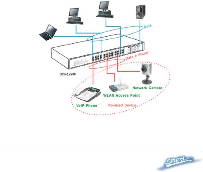
Thank you and congratulations on your purchase of the DES-1228P 24-Port 10/100Mbps Fast Ethernet + 4 10/100/1000Base-T Ports and 2 Combo SFP PoE Web-Smart Switch. This device integrates 1000Mbps Gigabit Ethernet, 100Mbps Fast Ethernet and 10Mbps Ethernet network capabilities in a highly flexible package. Since Ports 1~24 of this Switch are Power over Ethernet (PoE) ports, it will automatically detect the presence of IEEE 802.3af compliant devices and will provide power through these PoE ports. The Switch provides up to 15.4Watts per port and can be connected to WLAN access points, IP phones, video cameras, and other PD devices. The Switch will automatically detect the network appliance's requirements, and the Switch will supply the required power current to each appliance.
Purpose
This guide will show you how to install and use the configuration functions of the DES-1228P Web-Smart Switch step-by-step.
Terms/Usage
In this guide, the term “Switch” (first letter capitalized) refers to the DES-1228P Smart Switch, and “switch” (first letter lower case) refers to other Ethernet switches. Some technologies refer to terms “switch”, “bridge” and “switching hubs” interchangeably, and both are commonly accepted for Ethernet switches.
1

INTRODUCTION
This chapter will describe the features of the DES-1228P and provide some background information about Ethernet/Fast Ethernet/Gigabit Ethernet switching technology.
Gigabit Ethernet Technology
Gigabit Ethernet is an extension of IEEE 802.3 Ethernet utilizing the same packet structure, format, and support for CSMA/CD protocol, full duplex, and management objects, but with a tenfold increase in theoretical throughput of over 100-Mbps Fast Ethernet and a hundredfold increase over 10-Mbps Ethernet. Since it is compatible with all 10-Mbps and 100-Mbps Ethernet environments, Gigabit Ethernet provides a straightforward upgrade without wasting existing investments in hardware, software, or trained personnel.
The increased speed and extra bandwidth offered by Gigabit Ethernet is essential to help solving network bottlenecks that frequently develop as more advanced computer users and newer applications continue to demand greater network resources. Upgrading key components, such as backbone connections and servers to Gigabit Ethernet technology can greatly improve network response times as well as significantly speed up the traffic between subnets.
Gigabit Ethernet enables fast optical fiber connections to support video conferencing, complex imaging, and similar data-intensive applications. Likewise, since data transfers occur 10 times faster than Fast Ethernet, servers outfitted with Gigabit Ethernet NIC’s are able to perform 10 times the number of operations in the same amount of time.
2

In addition, the phenomenal bandwidth delivered by Gigabit Ethernet is the most cost-effective method to take advantage of today and tomorrow’s rapidly improving switching and routing internetworking technologies. And with expected advances in the coming years in silicon technology and digital signal processing that will enable Gigabit Ethernet to eventually operate over unshielded twisted-pair (UTP) cabling, outfitting your network with a powerful 1000-Mbps- capable backbone/server connection which will create a flexible foundation for the next generation of network technology products.
Fast Ethernet Technology
The growing importance of LANs and the increasing complexity of desktop computing applications are fueling the need for high performance networks. A number of high-speed LAN technologies have been proposed to provide greater bandwidth and improve client/server response times. Among them, 100BASE-T (Fast Ethernet) provides a non-disruptive, smooth evolution from the current 10BASE-T technology. The non-disruptive and smooth evolution nature, and the dominating potential market base, virtually guarantees cost-effective and high performance Fast Ethernet solutions.
100Mbps Fast Ethernet is a standard specified by the IEEE 802.3 LAN committee. It is an extension of the 10Mbps Ethernet standard with the ability to transmit and receive data at 100Mbps, while maintaining the CSMA/CD Ethernet protocol. Since the 100Mbps Fast Ethernet is compatible with all other 10Mbps Ethernet environments, it provides a straightforward upgrade and utilizes existing investments in hardware, software, and personnel training.
3

Switching Technology
Another approach to push beyond the limits of Ethernet technology is the development of switching technology. A switch bridges Ethernet packets at the MAC address level of the Ethernet protocol transmitting among connected Ethernet or Fast Ethernet LAN segments.
Switching is a cost-effective way of increasing the total network capacity available to users on a local area network. A switch increases capacity and decreases network loading by dividing a local area network into different segments, which won’t compete with each other for network transmission capacity.
The switch acts as a high-speed selective bridge between the individual segments. The switch, without interfering with any other segments, automatically forwards traffic that needs to go from one segment to another. By doing this the total network capacity is multiplied, while still maintaining the same network cabling and adapter cards.
Power over Ethernet (PoE)
Power over Ethernet (PoE) integrates power and data onto one single cabling infrastructure, eliminating the need to have AC power available at all locations.
Power and Data are integrated category 5/5e up to 100 Meters, compatible devices, such as IP points, and IP security cameras.
onto the same cable. Supporting PoE will provide power to PoE telephones, wireless LAN access
4

PoE is already widely adopted in the market, saving up to 50% of overall installation costs by eliminating the need to install separate electrical wiring and power outlets.
Features
♦Address Table: Supports up to 8K MAC address per device
♦Supports a packet buffer of up to 128K Bytes
♦1-24 10/100M ports support up to 15.4W power which complies the IEEE802.3af Power over Ethernet standard.
♦IGMP Snooping support
♦IEEE802.1D Spanning Tree
♦Support static Port Trunk
♦IEEE802.3x flow control in full duplex mode
♦Port Mirroring support
♦IEEE802.1Q VLAN
♦IEEE802.1p Priority Queues
♦IEEE802.1x Port-based Access Control
♦Supports Broadcast Storm Control
♦Supports Static MAC setting
♦D-Link Safeguard Engine support
♦Supports Simple Network Management Protocol(SNMP)
♦MIB support for: RFC1213 MIB II, Private MIB
♦Supports DHCP client
♦Supports Port setting for Speed, Duplex Mode
5

♦Easy configuration via Web Browser
♦Easy setting via SmartConsole Utility
♦Firmware backup and upload via Web GUI
♦System reboot via Web GUI
♦Provides parallel LED display for port status such as link/act, speed, etc.
♦Reset configuration (hardware and Web GUI)
Technical Specifications
Key Components / Performance
Switching Capacity |
12.8Gbps |
10M: 14,880 pps
Max. Forwarding Rate 100M: 148,809 pps 1G: 1,488,095 pps
Forwarding Mode |
Store and Forward |
|
|
Packet Buffer memory 128K Bytes |
|
|
|
SDRAM for CPU |
8M Bytes |
|
|
Flash Memory |
Prom 2M Bytes |
Port Functions
|
- 24 x 10/100BaseT ports |
LAN |
- Compliant with the following standards: |
|
IEEE 802.3 compliance |
|
|
6
|
1. |
IEEE 802.3u compliance |
|
|
2. |
Supports Full-Duplex operations at |
|
|
|
10/100Mbps, and 1000Mbps only on |
|
|
|
SFP ports |
|
|
- 2 Combo 1000Base-T/SFP ports |
||
|
-1000Base-T ports compliant to the |
||
|
following standards: |
||
|
1. IEEE 802.3 compliance |
||
|
2. IEEE 802.3u compliance |
||
|
3. IEEE 802.3ab compliance |
||
|
4. Support Full-Duplex operations |
||
|
- SFP Transceivers Supported: |
||
|
1. |
DEM-310GT (1000BASE-LX) |
|
|
2. |
DEM-311GT (1000BASE-SX) |
|
Combo ports in the |
3. |
DEM-314GT (1000BASE-LH) |
|
front panel |
4. |
DEM-315GT (1000BASE-ZX) |
|
5. |
DEM-312GT2 (1000BASE-SX), up to |
||
|
|||
|
|
2km |
|
|
6. |
DEM-210 (100BASE-FX), up to 2km, |
|
|
|
Multi-Mode |
|
|
7. |
DEM-211 (100BASE-FX), up to 15km, |
|
|
|
Single-Mode |
|
|
-WDM Transceivers Supported: |
||
|
1. |
DEM-330T (TX-1550/RX-1310nm), up |
|
|
|
to 10km, Single-Mode |
|
|
2. |
DEM-330R (TX-1310/RX-1550nm), up |
|
|
|
to 10km, Single-Mode |
|
|
3. |
DEM-331T (TX-1550/RX-1310nm), up |
|
|
|
to 40km, Single-Mode |
|
|
|
|
|
7

|
|
4. |
DEM-331R (TX-1310/RX-1550nm), up |
|
|
|
|
to 40km, Single-Mode |
|
|
|
- Compliant to following standards: |
|
|
|
|
1. |
IEEE 802.3z compliance |
|
|
|
2. |
IEEE 802.3u compliance |
|
|
|
|
|
|
|
|
2 1000Base-T ports |
|
|
|
1000Mbps Copper |
1000Base-T ports compliant to following |
|
|
|
standards: |
|
||
|
ports in the front |
|
||
|
1. |
IEEE 802.3 compliance |
|
|
|
panel |
|
||
|
2. |
IEEE 802.3u compliance |
|
|
|
|
|
||
|
|
3. |
IEEE 802.3ab compliance |
|
|
|
4. Support Full-Duplex operations |
|
|
|
|
|
|
|
|
Power over Ethernet |
|
|
|
|
|
|
|
|
|
PoE Capable Ports |
Port 1-24 |
|
|
|
|
|
|
|
|
|
1. Supplies power to PD device up to 15.4W |
|
|
|
|
per port, meeting IEEE802.3af standards and |
|
|
|
|
more sufficiently is able to provide power to PD |
|
|
|
|
devices |
|
|
|
|
2. Power Budget: 170W max |
|
|
|
PoE Specification |
3. Auto discovery feature, automatically |
|
|
|
recognize the connection of PD device and |
|
||
|
|
immediately sends power to it |
|
|
|
|
4. Auto disable port if the port current is over |
|
|
|
|
350mA while other ports remain active |
|
|
|
|
5. Active circuit protection, automatically |
|
|
|
|
disables the port if there is a short while other |
|
|
|
|
ports remain active |
|
|
|
|
|
|
|
|
|
|
|
|
|
|
|
8 |
|

|
6. Provide the power following the |
|
||||
|
classification below |
|
|
|||
|
|
|
|
|
|
|
|
|
Class |
Usage |
|
Minimum power |
|
|
|
|
|
|
levels at output of |
|
|
|
|
|
|
PSE |
|
|
|
0 |
Default |
|
15.4W |
|
|
|
1 |
Optional |
|
4.0W |
|
|
|
2 |
Optional |
|
7.0W |
|
|
|
3 |
Optional |
|
15.4W |
|
|
|
4 |
Reserved |
|
15.4W |
|
|
7. DES-1228P follow the PSE pinout standard |
|
||||
|
of Alternative A which is sending out power |
|
||||
|
over number 1,2,3,6 pins of 8 wires of CAT5 |
|
||||
|
UTP cable |
|
|
|
|
|
|
|
|
|
|
|
|
Chassis |
|
|
|
|
|
|
|
|
|
||||
Dimensions |
19-inch, 1U Rack-mount size |
|
||||
440mm x 210mm x 44mm |
|
|||||
|
|
|||||
|
|
|
|
|
|
|
Reset button on the |
A factory reset button x 1 |
|
|
|||
front panel |
|
|
||||
|
|
|
|
|
|
|
|
|
|
|
|
|
|
Physical & Environment |
|
|
|
|
||
|
|
|
|
|||
AC input |
100~240 VAC, 50/60Hz |
|
|
|||
|
Internal universal power supply |
|
||||
|
|
|
|
|
|
|
Operation |
0~40°C |
|
|
|
|
|
Temperature |
|
|
|
|
||
|
|
|
|
|
|
|
|
|
|
|
|
|
|
Storage Temperature |
-10~70°C |
|
|
|
|
|
|
|
|
|
|
|
|
9

Humidity |
Operation: 10%~90% RH |
|
Storage: 5%~90% RH |
||
|
||
|
|
|
Power consumption |
222 watts |
|
|
|
|
Heat Dissipation |
750.2 btu/hr |
|
|
|
|
MTBF |
149,676 (hours) |
|
|
|
Emission (EMI) and Safety Certifications
EMI-EMC Compliance: FCC class A, CE Class A, VCCI Class A Safety Compliance: cUL, UL
10

UNPACKING AND INSTALLATION
This chapter provides unpacking and installation information for the Web-Smart Switch.
Unpacking
Carefully unpack the contents of the Web-Smart Switch from the box and locate the following items:
One DES-1228P Web-Smart Switch
One AC power cord, suitable for the local electrical power voltage requirements
Four rubber feet to be used for shock cushioning Screws and two mounting brackets
CD-Rom with the SmartConsole Utility application, which includes the full User’s Guide
Quick Installation Guide
If any item is found missing or damaged, please contact the reseller for replacement.
Installation
The site chosen for installation greatly affects the Web-Smart Switch’s performance. When installing, consider the following points:
Install the Switch in a fairly cool and dry place. Technical Specifications such as operating temperatures and other important information can be found on page 8 of this manual.
11
Install the Switch in a site free from strong electromagnetic field generators (such as motors), vibration, dust, and direct exposure to sunlight.
Leave at least 10cm (about 4 inches) of space to the front and rear of the Switch for ventilation.
Install the Switch on a sturdy, level surface that can support its weight, or in an EIA standard-size equipment rack. For information on rack installation, see the next section, Rack Mounting.
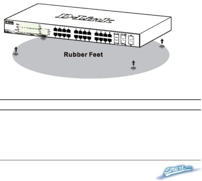
When installing the Switch on a level surface, attach the rubber pads (feet) to the bottom. The rubber feet cushion the switch and helps protect the case from scratches.
Figure 1 – Attach the adhesive rubber pads to the bottom
Rack Mounting
The Switch can be mounted in an EIA standard-size, 19-inch rack or chassis, which can be placed in a wiring closet with other equipment. Attach the mounting brackets to both sides of the Switch (one on each side), and secure them with the provided screws.
12
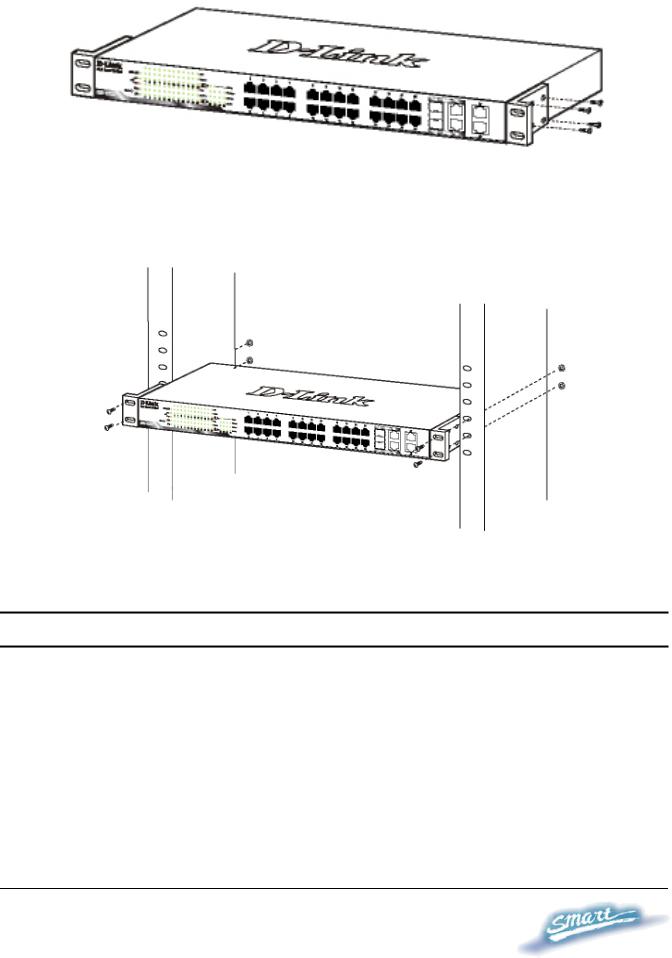
Figure 2 – Attach the mounting brackets to the Switch
Use the screws provided with the equipment rack or chassis to mount the Switch in the rack.
Figure 3 – Mount the Switch in the rack or chassis
Connecting Network Cables
The DES-1228P has 24 ports that support 10/100Mbps Fast Ethernet; it also has 4 10/100/1000Base-T Ports and 2 Combo SFPs. Each port on the DES-1228P supports Auto-MDI/MDI-X. Auto-MDI/MDI-X is a feature that enables the switch to auto sense what kind of cable is used on a port (straight or crossover). This allows any type of cables to be used with the switch regardless of what device is being connected.
13

AC Power
The Switch utilizes an AC power supply 100~240V AC, 50~60Hz. The power switch is located at the rear of the unit adjacent to the AC power connector and the system fan.
The switch’s power supply will adjust to the local power source automatically and may be turned on without having any or all LAN segment cables connected.
14
IDENTIFYING EXTERNAL COMPONENTS
This chapter describes the front panel, rear panel, and LED indicators of the Switch.
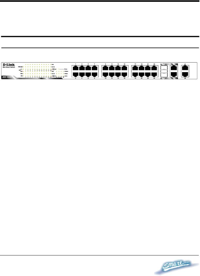
Front Panel
The figure below shows the front panel of the Switch.
Figure 4 – Front panel of the 28-port Web-Smart Switch
LED Indicator:
Comprehensive LED indicators display the status of the switch and the network (see the Understanding LED Indicators section).
10/100 BASE-TX Twisted Pair Ports (Port 1~24)
The DES-1228P is equipped with 24 Fast Ethernet twisted pair ports that are auto-negotiable 10/100Mbps and also support auto MDI/MDIX crossover detection. All these 24 ports can operate in halfand fullduplex modes, and will be automatically activated when a compatible terminal is identified. The Switch will provide the power needed through the PoE port to the connected PD.
For Legacy devices that are not yet compatible, the PoE port will not offer the power to these devices. This feature allows users to freely and safely mix legacy and Power over Ethernet compatible devices on their network.
15
10/100/1000 BASE-T / Mini GBIC Combo Ports (Option Port 25~26)
The Switch is also equipped with two combo 10/100/1000 Base-T / Mini GBIC ports, supporting optional 100BASE-FX or 1000BASESX/LX Mini GBIC modules for fiber uplinks.
10/100/1000 BASE-T Twisted Pair Ports (Port 27~28)
Finally there are 2 Gigabit twisted pair ports that are auto negotiable 10/100/1000Mbps with auto MDI/MDIX crossover detection support that can also operate in halfand fullduplex modes.
Note: When a port is set to “Forced Mode”, the Auto MDI/MDIX is disabled.
16
Rear Panel
AC Power Connector
Figure 5 – Rear panel of the Switch
AC Power Connector:
Plug in the female connector of the provided power cord into this connector, and the male into a power outlet. Supported input voltages range from 100-240V AC, and 50-60Hz.
Understanding LED Indicators
The front panel LEDs provides instant status feedback and simplifies monitoring and troubleshooting tasks.
Figure 6 – LED indicators of the Switch
Reset button:
The Reset button resets all configuration settings back to the factory
17

default.
Note: Be sure that to record all custom settings of the Switch before pressing the reset button. Resetting the Switch back to factory default settings will erase all custom configurations.
Power and System LEDs
Power LEDs
On |
When the Power LED light is on, the Switch is receiving |
|
|
power. |
|
|
|
|
Off |
When the Power LED light is off, the power cord is not |
|
|
or improperly connected. |
|
|
|
|
CPU LEDs ( Management Indicator) |
||
Blinking |
When the CPU is working, the CPU LED is blinking. |
|
|
|
|
Off |
The CPU is idle. |
|
|
|
|
Ports 1 ~ 24 Status LEDs |
||
Link/Act |
|
|
|
|
|
On |
When the Link/Act LED light is on, the respective port is |
|
|
successfully connected to an Ethernet network. |
|
|
|
|
Blinking |
When the Link/Act LED is blinking, the port is |
|
|
transmitting or receiving data on the Ethernet network. |
|
|
|
|
Off |
No link. |
|
|
|
|
|
|
|
|
18 |
|

100Mbps
On |
When the 100Mbps LED light is on, the respective port |
|
is connected to a 100Mbps Fast Ethernet network. |
|
|
Off |
When the respective port is connected to a 10Mbps |
|
Ethernet or no link. |
|
|
PoE |
|
|
|
Green |
When the Green light is on, the respective port is |
Light |
providing 48V of power. |
|
|
Off |
When the light is off, either the respective port is |
|
receiving power from an AC power source or no 802.3af |
|
PD is found. |
|
|
Red Light |
When the Red light is on, an error has occurred at the |
|
respective port. |
|
|
Option Ports 25~26 10/100/1000 Base-T / Mini-GBIC Status LEDs FX Link
On |
When the FX Link LED light is on, the respective port is |
|
connected to a 100 or 1000Mbps Gigabit Ethernet |
|
network. |
|
|
Off |
No link or linking to copper ports. |
|
|
19

Link/Act
On |
|
When the respective combo port is connected to a |
|
|
network, the Link/Act LED light is on. |
|
|
|
Blinking |
|
When the LED is blinking, the respective combo port is |
|
|
transmitting or receiving data on a network. |
|
|
|
Off |
|
No link. |
|
|
|
1000Mbps |
|
|
|
|
|
On |
|
When the 1000Mbps LED light’s on, the respective port |
|
|
is connected to a 1000Mbps Gigabit Ethernet network. |
|
|
|
Off |
|
When the respective port is connected to a 100Mbps Fast |
|
|
Ethernet or no link. |
|
|
|
100Mbps |
|
|
|
|
|
On |
|
When the 100Mbps LED lights on, the respective port is |
|
|
connected to a 100Mbps Fast Ethernet network. |
|
|
|
Off |
|
When the respective port is connected to a 1000Mbps |
|
|
Gigabit Ethernet network or no link. |
|
|
|
Ports 27~28 10/100/1000 Base-T LEDs
Link/Act
On |
When the Link/Act LED light is on, the respective port is |
|
successfully connected to an Ethernet network. |
|
|
20

Blinking |
|
When the Link/Act LED is blinking, the port is |
|
|
transmitting or receiving data on the Ethernet network. |
|
|
|
Off |
|
No link. |
|
|
|
1000Mbps |
|
|
|
|
|
On |
|
When the 1000Mbps LED light is on, the respective port |
|
|
is connected to a 1000Mbps Gigabit Ethernet network. |
|
|
|
Off |
|
When the respective port is connected to a 10Mbps |
|
|
Ethernet or 100Mbps Fast Ethernet network, or no link. |
|
|
|
100Mbps |
|
|
|
|
|
On |
|
When the 100Mbps LED light is on, the respective port |
|
|
is connected to a 100Mbps Fast Ethernet network. |
|
|
|
Off |
|
When the respective port is connected to a 10Mbps |
|
|
Ethernet or 1000Mbps Gigabit Ethernet network. |
|
|
|
21

CONFIGURATION
Through a web browser, the features and functions of the DES-1228P Switch can be configured for optimum use.
Supported web browsers
The embedded Web-based Utility currently supports the following web browsers:
•Microsoft Internet Explorer ver. 6.0, 5.5
•Mozilla ver. 1.7.12, 1.6
•Firefox ver. 1.5, 1.0.7
•Netscape ver. 8.0.4, 7.2
•Opera ver. 8.5, 7.6
•Safari ver. 2.0.2
Installing the SmartConsole Utility
The SmartConsole Utility allows a user to monitor and configure multiple D-Link Web-Smart Switches from a workstation connected to the network. Follow these steps to install the SmartConsole Utility:
1.Insert the Utility CD in your CD-Rom Drive.
2.From the Start menu on the Windows desktop, choose Run.
3.In the Run dialog box, type D:\SmartConsole Utility\setup.exe (where D:\ represents the drive letter of your CD-Rom) and click
OK.
4.Follow the on-screen instructions to install the utility program.
5.Upon completion, go to Program Files > SmartConsole Utility and execute the SmartConsole Utility.
22

SmartConsole Utility Features
The SmartConsole Utility is divided into four parts, a Menu Toolbar of functions at the top, Discovery List, Monitor List, and Device Setting.
Figure 7 – SmartConsole Utility
Menu Toolbar
The Menu Toolbar in the SmartConsole Utility has four main tabs, File, View, Option, and Help.
File includes: Monitor save, Monitor save as, Monitor load and Exit.
•Monitor Save: To record the setting of the Monitor List as default for the next time the SmartConsole Utility is used.
•Monitor Save As: To record the setting of the Monitor List in an appointed filename and file path.
23

•Monitor Load: To manually load a Monitor List setting file.
•Exit: To exit the SmartConsole Utility.
View includes: View log and Clear Log functions, which provide trap setting list operations.
•View Log: To show the event of the SmartConsole Utility and the device.
•Clear Log: To clear all log entries.
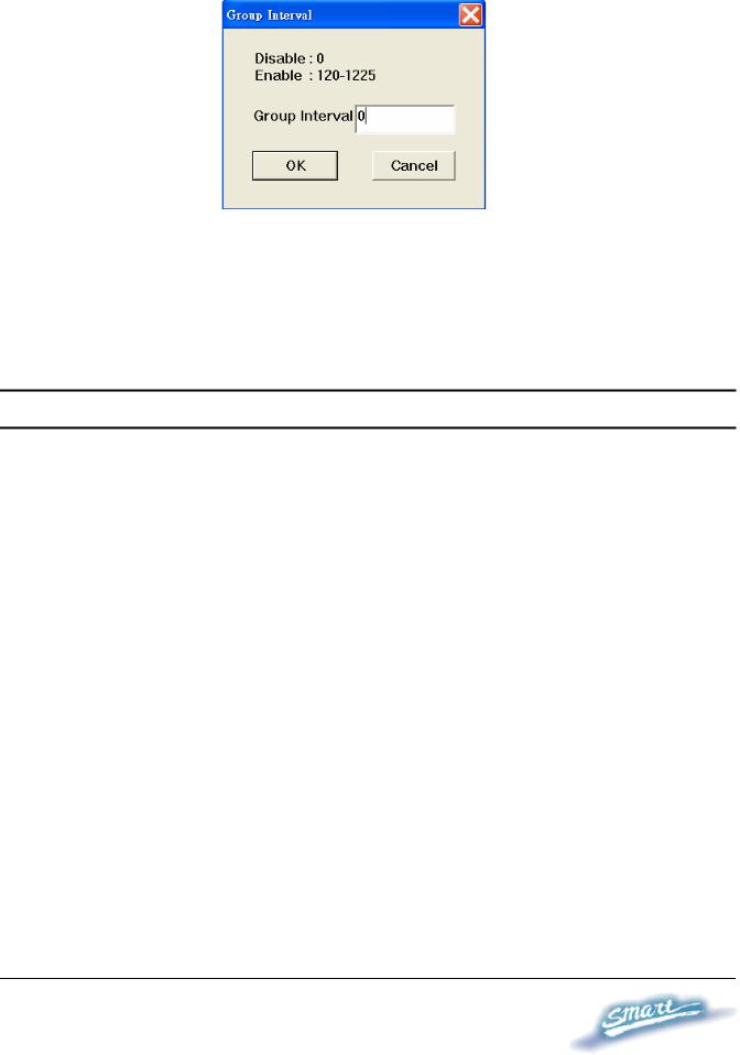
Option includes: Refresh Time and Group Interval functions.
•Refresh time refreshes the monitoring time of the device. Choices include 15 secs, 30 secs, 1 min, 2 min and 5 min for selecting the monitoring time intervals.
•Group Interval establishes the intervals (in seconds) that the Web-Smart Switch will be discovered in the SmartConsole Utility Discovery List.
NOTE: If the Group Interval is set to 0, IGMP snooping must be disabled or else the Web-Smart Switch will not be discovered.
24
Help includes: information About the SmartConsole Utility, such as the software version.
Discovery List
This is the list where all Web-Smart devices on the network are discovered.
By pressing the Discovery button, all the Web-Smart devices are listed in the discovery list.
Double click or press the Add to monitor list button to select a device from the Discovery List to the Monitor List.
Definitions of the Discovery List features:
MAC Address: Shows the device MAC Address.
IP Address: Shows the current IP addresses of devices. Protocol version: Shows the version of the Utility protocol. Product Name: Shows the device product name.
System Name: Shows the appointed device system name.
25

DHCP: Uses a client/server model to obtain lease of an IP address from a DHCP server as part of the network boot process.
Location: Shows where the appointed device location.
Trap IP: Shows the IP where the Trap information will be sent. Subnet Mask: Shows the Subnet Mask set of the device. Gateway: Shows the Gateway set of the device.
Group Interval: Shows the Group Interval of the device.
Monitor List
All Web-Smart devices in the Monitor List can be monitored, with Trap information available to be received for monitoring status information of the device.
Definitions of the Monitor List functions and terms:
S: Shows the system symbol of the Web-Smart device,  represents the device system is inactive.
IP Address: Shows the current IP address of the device. MAC Address: Shows the device MAC Address.
Protocol version: Shows the version of the Utility protocol. Product Name: Shows the device product name.
System Name: Shows the appointed device system name.
DHCP: uses a client/server model to obtain lease of an IP address from a DHCP server as part of the network boot process.
Location: Shows where the device is located. Trap IP: Shows the IP where the Trap to be sent.
Subnet Mask: Shows the Subnet Mask set of the device. Gateway: Shows the Gateway set of the device.
26
 Loading...