


Getting Started Guide
Erste Schritte
Guide de démarrage Guida introduttiva Guía de introducción
Краткое руководство пользователя
Guia inicial
Petunjuk Pemasangan
About This Guide
This guide gives step-by-step instructions for setting up all D-Link Web Smart switches. Please note that the model you have purchased may appear slightly different from those shown in the illustrations.
For more detailed information about your switch, its components, making network connections, and technical specifications, please refer to the User’s Guide included with your switch.
Step 1 – Unpacking
Open the shipping carton and carefully unpack its contents. Please consult the packing list located in the User Guide to make sure all items are present and undamaged. If any item is missing or damaged, please contact your local D-Link reseller for replacement.
-One D-Link Web Smart Switch
-Rack mounting bracket
-Power cord
-User’s Guide CD with SmartConsole Utility program
-One multilingual Getting Started Guide
Step 2 – Switch Installation
For safe switch installation and operation, it is recommended that you:
♦Visually inspect the power cord to see that it is secured fully to the AC power connector
♦Make sure that there is proper heat dissipation and adequate ventilation around the switch
♦Do not place heavy objects on the switch
Desktop or Shelf Installation
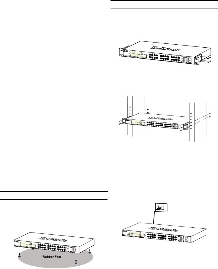
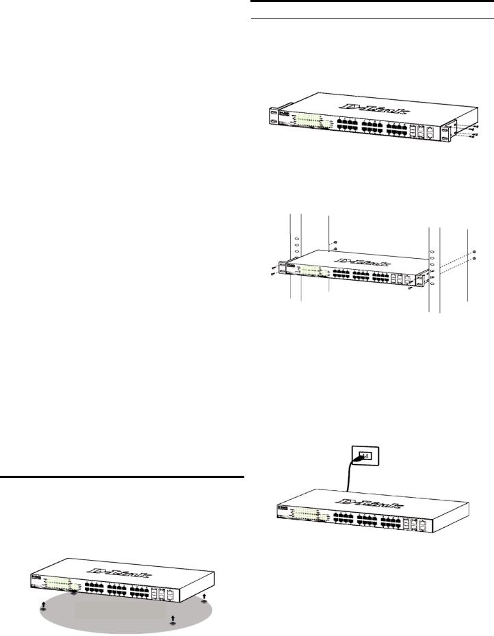
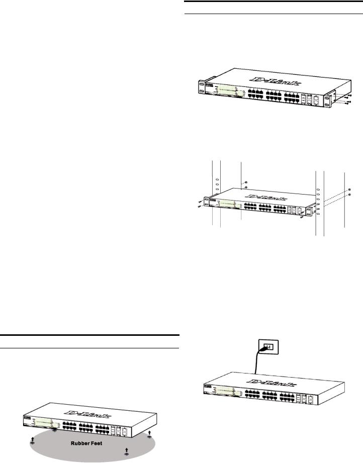
When installing the switch on a desktop or shelf, the rubber feet included with the device must be attached on the bottom at each corner of the device’s base. Allow enough ventilation space between the device and the objects around it.
Figure 1. Attaching the rubber feet
Rack Installation
The switch can be mounted in an EIA standard size 19inch rack, which can be placed in a wiring closet with other equipment. To install, attach the mounting brackets to the switch’s side panels (one on each side) and secure them with the screws provided.
Figure 2. Attaching the mounting brackets
Then, use the screws provided with the equipment rack to mount the switch in the rack.
Figure 3. Installing the switch in a standard-sized equipment rack
Step 3 – Plugging in the AC Power
Cord
You can now connect the AC power cord into the rear of the switch and to an electrical outlet (preferably one that is grounded and surge protected).
Figure 4. Plugging the switch into an outlet
Power Failure
As a precaution, the switch should be unplugged in case of power failure. When power is resumed, plug the switch back in.
2
Management Options
The D-Link Web Smart Switch can be managed in-band by using Telnet. The user may also choose the Web-based Management, accessible through a web browser or through any PC using the SmartConsole Utility.
If you want to manage only one D-Link Web Smart Switch, the Web-Based Management is the better option. Each switch must be assigned its own IP Address, which is used for communication with Web-Based Management or an SNMP network manager and the PC should have an IP address in the same range as the switch.
However, if you want to manage multiple D-Link Web Smart Switches, the SmartConsole Utility is the better option. Using the SmartConsole Utility, you don’t need to change the IP address of your PC and it is easy to start the initial setting of multiple Smart Switches.
Please refer to the following detailed installation instructions for the Web-Based Management, SmartConsole Utility, Telnet Management and SNMPBased Management.
Web-based Management Interface
After a successful physical installation, you can configure the switch, monitor the LED panel, and display statistics graphically using a web browser, such as Netscape Navigator (version 6.2 and higher) or Microsoft® Internet Explorer (version 5.0 and higher).
You need the following equipment to begin the web configuration of your device:
A PC with a RJ-45 Ethernet connection
A standard Ethernet cable
Step 2
In order to login and configure the switch via an Ethernet connection, the PC must have an IP address in the same range as the switch. For example, if the switch has an IP address of 10.90.90.90, the PC should have an IP address of 10.x.y.z (where x/y is a number between 0 ~ 254 and z is a number between 1 ~254), and a subnet mask of 255.0.0.0.
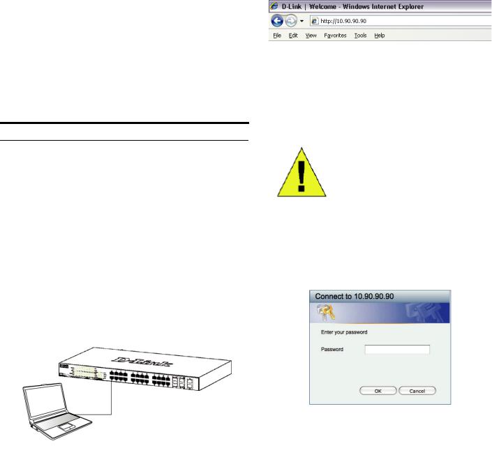
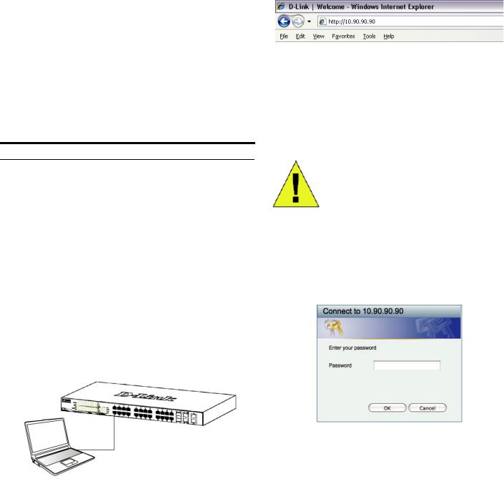
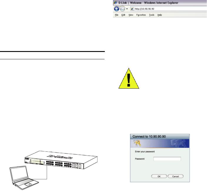
Open your web browser and enter http://10.90.90.90 (the factory-default IP address) in the address box. Then press <Enter>.
Figure 7. Enter the IP address 10.90.90.90 in the web browser
The web configuration can also be accessed through the
SmartConsole Utility. Open the SmartConsole Utility and double-click the switch as it appears in the Device List. This will automatically load the web configuration in your web browser.
NOTE: The switch's factory default IP address is 10.90.90.90 with a subnet mask of 255.0.0.0 and a default gateway of 0.0.0.0
Step 3
When the following logon box appears, enter “admin” for the password. Press OK to enter the main configuration window.
Step 1
Connect the Ethernet cable to any of the ports on the front panel of the switch and to the Ethernet port on the PC.
Figure 8. User authentication window
Figure 6. Connected Ethernet cable
3
Step 4
Before entering the Web-based Management, the Smart Wizard will guide you to quickly configure some functions, such as Password Settings, SNMP Settings, and
System Settings. If you don’t plan to change anything, click Exit to exit the Wizard and enter the Web-based Management. For a detailed look at the Smart Wizard’s functions, please refer to the Smart Wizard introduction in the user manual.
SmartConsole Utility
The SmartConsole Utility included on the installation CD is a program for discovering Smart Switches with the same L2 network segment connected to your PC. This tool is only for computers running Windows 2000, Windows XP, and Windows Vista x64/86 operating systems. There are two options for the installation of SmartConsole Utility, one is through the autorun program on the installation CD and the other is manual installation.
Note: Please be sure to remove any existing SmartConsole Utility from your PC before installing the latest SmartConsole Utility.
Option 1: Follow these steps to install the SmartConsole Utility via the autorun program on the installation CD.
1.Insert the Utility CD into your CD-Rom Drive.
2.The autorun program will pop up automatically
3.Simply click on the ”Install SmartConsole Utility” button and an installation wizard will guide you through the process.
4.After successfully installing the SmartConsole Utility, you can open the utility by clicking Start > Programs >
D-Link SmartConsole Utility.
5.Just connect the Smart Switch to the same L2 network segment of your PC and use the SmartConsole Utility to discover the Smart Switches.
Option 2: Follow these steps to install the SmartConsole Utility manually.
1.Insert the Utility CD into your CD-Rom Drive.
2.From the Start menu on the Windows desktop, choose Run.
3.In the Run dialog box, type D:\D-Link SmartConsole Utility\D-Link_SmartConsole_Utility_v3.00.10.exe (where D:\ represents the drive letter of your CD-Rom) and click OK.
4.Follow the on-screen instructions to install the utility.
5.Upon completion, go to Start > Programs > D-Link SmartConsole Utility and open the SmartConsole Utility.
6.Just connect the Smart Switch to the same L2 network segment of your PC and use the SmartConsole Utility to discover the Smart Switches.
For a detailed look at SmartConsole’s functions, please refer to the SmartConsole Utility introduction in the user manual.
Telnet Management
Users may also access the switch through Telnet using your PC’s Command Prompt. To access it from your computer, users must first ensure that a valid connection is made through the Ethernet port of the Switch and your PC, and then click Start > Programs > Accessories > Command Prompt on your computer. Once the console window opens, enter the command telnet 10.90.90.90 (depending on configured IP address) and press Enter on your keyboard. You should be directed to the opening console screen for the Command Line Interface of the switch, enter the “admin” for the default user name and password for the Switch and press the Enter key.
SNMP-Based Management
You can manage the Switch with D-Link D-View or any SNMP-compatible program. The SNMP function is default Disabled for D-Link Web Smart switches.
Additional Information
If you are encountering problems setting up your network, please refer to the user manual that came with the switch. It contains many more rules, charts, explanations, and examples to help you get your network up and running.
Additional help is available through our offices listed at the back of the user manual or online. To find out more about D-Link products or marketing information, please visit the website http://www.dlink.com.tw; for any support issue, please visit the website http://support.dlink.com.tw, which will re-direct you to appropriate local D-Link website.
4

5
Über dieses Handbuch
Diese Kurzanleitung für die Installation hilft Ihnen Schritt für Schritt bei der Inbetriebnahme aller Web Smart Switches von D-Link. Bitte beachten Sie, dass das von Ihnen erworbene Modell im äußeren Erscheinungsbild leicht von den in den Illustrationen abgebildeten Modellen abweichen kann.
Einzelheiten über Ihr Gerät, seine Komponenten, das Einrichten von Netzwerkverbindungen sowie die technischen Daten können Sie dem mitgelieferten Benutzerhandbuch entnehmen.
Schritt 1 – Auspacken
Öffnen Sie die Transportverpackung, und entnehmen Sie vorsichtig den Inhalt. Vergewissern Sie sich anhand der Packliste im Benutzerhandbuch, dass alle Bestandteile vollständig und unbeschädigt vorhanden sind. Sollte eines der Teile fehlen oder beschädigt sein, wenden Sie sich bitte an Ihren D-Link-Fachhändler.
-Ein D-Link Web Smart Switch
-Einbauwinkel
-Stromkabel
-CD-ROM mit Benutzerhandbuch und dem Dienstprogramm SmartConsole
-Eine Kurzanleitung in mehreren Sprachen
Schritt 2 – Switch installieren
Abbildung 1: Gummifüße anbringen
Rackmontage
Der Switch kann in einem 19-Zoll-Rack (EIAStandardgröße) montiert und mit weiteren Geräten in einem Verkabelungsschrank installiert werden. Bringen Sie an jedem Seitenblech des Switch einen Einbauwinkel an, und schrauben Sie die Winkel mit den beiliegenden Schrauben fest.
Abbildung 2: Einbauwinkel anbringen
Montieren Sie danach den Switch im Einschub mit den Schrauben, die Sie zu Ihrem Rack erhalten haben.
Abbildung 3: Switch im Standardrack installieren
Gehen Sie zum sicheren Installieren und Betreiben des Switch wie folgt vor:
♦Vergewissern Sie sich, dass das Stromkabel unbeschädigt ist, und achten Sie auf den festen Sitz der Steckverbindungen.
♦Sorgen Sie für eine funktionierende Wärmeableitung und eine ausreichende Belüftung in der Umgebung des Switch.
♦Stellen Sie keine schweren Gegenstände auf den Switch.
Schritt 3 – An die Stromversorgung anschließen
Schließen Sie das Stromkabel an eine Steckdose (möglichst geerdet und mit Überspannungsschutz) und an den Netzanschluss auf der Rückseite des Switch an.
Tischoder Regalmontage
Wenn Sie den Switch auf einem Tisch oder in einem Regal aufstellen möchten, bringen Sie vorher die mitgelieferten Gummifüße in den vier Ecken an der Unterseite des Gehäuses an. Lassen Sie um das Gerät herum genug Platz zur Belüftung frei.
Abbildung 4: Switch an die Stromversorgung anschließen
Stromausfall
Aus Sicherheitsgründen sollten Sie bei einem Stromausfall den Netzstecker ziehen. Ist die Stromversorgung wieder gewährleistet, können Sie den Netzstecker des Switch wieder einstecken.
6
Verwaltungsoptionen
Mithilfe von Telnet ist ein In-Band-Management des Web Smart Switch von D-Link möglich. Sie können aber auch das webbasierte Management wählen, auf das Sie über einen Webbrowser oder über jeden PC zugreifen können, der die SmartConsole Utility verwendet.
Wenn Sie nur einen D-Link Web Smart Switch verwalten möchten, eignet sich dafür am besten die webbasierte Verwaltungsoberfläche. Jedem Switch muss eine eigene IP-Adresse zugewiesen werden, die für die Kommunikation mit dem webbasierten Verwaltungsprogramm oder einem SNMP-Netzwerkmanager verwendet wird. Die IPAdresse des PC sollte im gleichen Bereich liegen wie die des Switch.
Wenn Sie mehrere D-Link Web Smart Switches verwalten möchten, verwenden Sie am besten das Dienstprogramm SmartConsole. In diesem Fall brauchen Sie die IPAdresse Ihres PC nicht zu ändern und die Ersteinstellung mehrerer Smart Switches kann auf einfache Weise vorgenommen werden.
In den folgenden Abschnitten dieser Anleitung finden Sie detaillierte Informationen zum webbasierten Verwaltungsprogramm und zum Dienstprogramm SmartConsole, Telnet-Management und SNMP-basiertes Management.
Die webbasierte Management-Benutzeroberfläche
Nach erfolgreicher Installation können Sie den Switch konfigurieren, die LED-Anzeigen überwachen und Statistiken grafisch über einen Webbrowser anzeigen lassen, z. B. mit Netscape Navigator (Version 6.2 und höher) oder Microsoft® Internet Explorer (Version 5.0 und höher).
Sie benötigen das folgende Zubehör, um mit der Webkonfiguration Ihres Geräts zu beginnen:
Einen PC mit einem RJ-45-Ethernet-Anschluss
Ein Standard-Ethernetkabel
Schritt 2
Zur Anmeldung und um den Switch über eine EthernetVerbindung zu konfigurieren, muss der PC eine IP-Adresse im gleichen Adressenbereich wie der Switch aufweisen. Beispiel: Wenn der Switch die IP-Adresse 10.90.90.90 hat, sollte der PC die IP-Adresse 10.x.y.z haben (wobei x/y eine Zahl zwischen 0 ~ 254 und z eine zwischen 1 ~254 ist) und eine Subnetzmaske 255.0.0.0.
Öffnen Sie Ihren Webbrowser, und geben Sie http://10.90.90.90 (die werkseitige Standard-IP-Adresse) in die Adresszeile ein. Drücken Sie anschließend die Eingabetaste.
Abbildung 7: IP-Adresse 10.90.90.90 in den Webbrowser eingeben
Die Webkonfiguration kann auch über das Dienstprogramm SmartConsole vorgenommen werden. Öffnen Sie SmartConsole, und doppelklicken Sie in der Geräteliste auf den Switch. Daraufhin wird die Webkonfiguration automatisch in Ihrem Webbrowser geladen.
HINWEIS: Die werkseitige Standard-IP-
Adresse des Switch lautet 10.90.90.90, die
Subnetzmaske 255.0.0.0 und das
Standard-Gateway 0.0.0.0
Schritt 3
Wenn der folgende Anmeldedialog angezeigt wird, geben Sie „admin“ als Kennwort ein. Klicken Sie anschließend auf OK.
Schritt 1
Verbinden Sie das Ethernetkabel mit einem beliebigen
Anschluss auf der Vorderseite des Switch und mit dem
Ethernetanschluss an Ihrem PC.
Abbildung 8: Benutzerauthentifizierung
|
Schritt 4 |
|
|
Bevor Sie jedoch das webbasierte Management |
|
Abbildung 6: Ethernetkabel anschließen |
verwenden, gibt Ihnen der Assistent (Smart Wizard) |
|
Anleitungen zur schnellen Konfiguration einiger Funktionen, |
||
|
7
wie zum Einrichten von Kennwörtern (Password Settings), |
5. |
Klicken Sie nach Abschluss der Installation zum |
den SNMP-Einstellungen (SNMP Settings) und den |
|
Starten des Dienstprogramms SmartConsole auf Start |
Systemeinstellungen (System Settings). Wenn Sie keine |
|
-> Programs (Programme) -> SmartConsole Utility. |
Änderungen geplant haben, klicken Sie auf Exit (Beenden), |
6. |
Schließen Sie den Smart Switch an das gleiche L2- |
um den Assistenten zu beenden und auf die webbasierte |
|
Netzwerksegment Ihres PC an, und führen Sie mit |
Management-Benutzeroberfläche zuzugreifen. Genaue |
|
SmartConsole eine Suche nach Smart Switches durch. |
Beschreibungen der Funktionen des Assistenten finden Sie
in der Einführung zum Smart Wizard im Benutzerhandbuch. Weitere Informationen zu den Funktionen von SmartConsole finden Sie im Benutzerhandbuch in der Einführung zu SmartConsole.
Das Telnet-Management
Zugriff auf den Switch ist auch über Telnet mithilfe der Eingabeaufforderungsfunktion Ihres PCs möglich. Dazu müssen Sie zunächst sicherstellen, dass über den Ethernet-Port des Switches und Ihrem PC eine Verbindung besteht. Klicken Sie dann auf Ihrem Computer auf Start > Programme > Zubehör> Eingabeaufforderung. Sobald das Console-Fenster geöffnet ist, geben Sie den Befehl telnet 10.90.90.90 (abhängig von der konfigurierten IP-Adresse) ein und drücken Sie auf die Eingabetaste auf Ihrer Tastatur. Damit wird das Hauptfenster der Console für die Befehlszeilen-Schnittstelle geöffnet. Geben Sie dort “admin” als standardmäßig vorgegebenen Benutzernamen und als Kennwort für den Switch ein und drücken Sie auf die Eingabetaste.
1. |
Legen Sie die CD in das CD-ROM-Laufwerk ein. |
Das SNMP-basierte Management |
|
||||
2. |
Das Installationsprogramm wird automatisch geöffnet. |
Die Verwaltung des Switches ist auch mit D-View von D- |
|||||
3. |
Klicken Sie auf die Schaltfläche Install SmartConsole |
||||||
Link oder jedem SNMP-kompatiblen Programm möglich. |
|||||||
|
Utility (SmartConsole installieren). |
Der |
daraufhin |
||||
|
Die |
SNMP-Funktion ist jedoch standardmäßig für Web |
|||||
|
angezeigte Installationsassistent wird |
Sie |
durch den |
||||
|
Smart Switches von D-Link deaktiviert. |
||||||
|
Installationsvorgang führen. |
|
|
||||
|
|
|
|
|
|
||
4. |
Nachdem Sie SmartConsole erfolgreich installiert |
Ergänzende Hinweise |
|||||
|
haben, können Sie das Dienstprogramm über Start > |
||||||
|
Programs (Programme) > D-Link SmartConsole |
Falls es bei der Konfiguration des Netzwerks Probleme gibt, |
|||||
|
Utility öffnen. |
|
|
||||
5. |
Schließen Sie den Smart Switch an das gleiche L2- |
schlagen Sie am besten zuerst im Benutzerhandbuch nach. |
|||||
Es |
enthält zusätzliche Richtlinien, Abbildungen, |
||||||
|
Netzwerksegment Ihres PC an, und führen Sie mit |
||||||
|
Erklärungen und Beispiele, die Sie bei Aufbau und |
||||||
|
SmartConsole eine Suche nach Smart Switches durch. |
||||||
|
|
|
|
Inbetriebnahme Ihres Netzwerks unterstützen. |
|||
2. Option: Führen Sie die folgenden Schritte durch, um das Dienstprogramm SmartConsole manuell zu installieren.
1.Legen Sie die CD in das CD-ROM-Laufwerk ein.
2.Klicken Sie unter Windows im Menü Start auf Run (Ausführen).
3.Geben Sie im Dialogfeld Run (Ausführen) folgende Befehlszeile ein : D:\D-Link SmartConsole Utility\ D-Link_SmartConsole_Utility_v3.00.10.exe (hierbei steht „D:“ für den Laufwerksbuchstaben Ihres CD- ROM-Laufwerks). Klicken Sie anschließend auf OK.
4.Befolgen Sie die Installationsanweisungen auf dem Bildschirm.
Weitere Hilfe erhalten Sie im Internet oder bei unseren Niederlassungen, die auf der Rückseite des Benutzerhandbuchs aufgelistet sind. Für weitere Informationen zu den Produkten von D-Link sowie Marketing-Informationen besuchen Sie die Website http://www.dlink.eu. Bei Support-Fragen gehen Sie ebenfalls auf diese Website http://support.dlink.com.tw. Hier werden Sie dann auf die entsprechende lokale D-Link- Seite geleitet.
8

9
À propos de ce guide
Ce guide vous explique, étape par étape, comment configurer tous les Smart Switches Web de D-Link. Remarque : il se peut que votre modèle d’appareil diffère légèrement de ceux illustrés dans le présent manuel.
Pour obtenir des informations plus détaillées sur votre switch, ses composants, ses connexions réseau et ses spécifications techniques, reportez-vous au Guide de l’utilisateur fourni dans son emballage.
Étape 1 : déballage
Ouvrez le carton d’expédition et sortez-en le contenu avec précaution. Le Guide de l’utilisateur contient une liste des éléments devant se trouver dans l’emballage ; en vous y reportant, vérifiez que tous les composants sont présents et en parfait état. Si un élément est absent ou détérioré, contactez votre revendeur D-Link pour en obtenir un nouveau.
-Un Smart Switch Web D-Link
-Un support pour montage en armoire
-Un cordon d’alimentation
-Le CD du Guide de l’utilisateur, incluant l’utilitaire SmartConsole
-Un guide de démarrage multilingue
Étape 2 : installation du switch
Pour installer et utiliser le switch en toute sécurité, nous vous recommandons de procéder comme suit :
Installation dans une armoire
Vous pouvez monter votre switch dans une armoire 19 pouces EIA standard, à insérer dans une armoire de câblage avec d’autres équipements. Pour cela, installez les supports sur les panneaux latéraux du switch (un de chaque côté) et fixez-les à l’aide des vis fournies.
Figure 2. Fixation des supports de montage
Utilisez ensuite les vis fournies pour monter le switch dans l’armoire.
Figure 3. Installation du switch dans une armoire de taille standard
♦Inspectez le cordon d’alimentation et assurez-vous Étape 3 : raccordement au secteur qu’il est parfaitement relié au connecteur
d’alimentation secteur.
♦Vérifiez que le switch présente une dissipation de chaleur adaptée et qu’il est entouré d’un espace suffisant pour garantir une bonne ventilation.
♦Ne posez pas d’objets lourds sur le switch.
À présent, reliez le switch à une prise de courant (de préférence mise à la terre et dotée d’un parasurtenseur) à l’aide du cordon d’alimentation secteur branché à l’arrière du switch.
Installation sur un bureau ou sur une étagère
Pour installer le switch sur un bureau ou une étagère, vous |
|
devez ajouter les pieds en caoutchouc fournis aux quatre |
|
coins de sa base. À des fins de ventilation, prévoyez un |
|
espace suffisant entre l’appareil et les objets environnants. |
Figure 4. Raccordement du switch à une prise de courant |
Panne de courant
En cas de panne de courant, par précaution, débranchez le switch. Rebranchez-le une fois le courant rétabli.
Pieds en caoutchouc
Figure 1. Fixation des pieds en caoutchouc
10
Options d’administration
Le commutateur Web intelligent D-Link peut être géré intrabande via Telnet. L'utilisateur peut aussi choisir l'interface de gestion Web, accessible par l'intermédiaire d'un navigateur Web ou de n'importe quel PC utilisant l'utilitaire SmartConsole.
Si vous ne souhaitez administrer qu’un seul Smart Switch Web D-Link, nous vous recommandons l’utilitaire de gestion Web. Chaque switch doit disposer de sa propre adresse IP pour communiquer avec l’utilitaire de gestion Web ou un gestionnaire de réseau SNMP. Par ailleurs, le PC doit être associé à une adresse IP comprise dans la même plage que celle du switch.
Cependant, si vous souhaitez gérer plusieurs Smart Switches Web D-Link, l’utilitaire SmartConsole est la meilleure solution. Grâce à l’utilitaire SmartConsole, vous n’avez plus besoin de changer l’adresse IP de votre PC et la configuration initiale de Smart Switches multiples est plus simple à lancer.
Pour savoir comment installer les utilitaires de gestion Web et SmartConsole, veuillez consulter les instructions détaillées suivantes, Interface de gestion Telnet et interface de gestion SNMP.
Étape 2
Pour pouvoir ouvrir une session et configurer le commutateur via une connexion Ethernet, l'adresse IP du PC doit être dans la même plage que celle du commutateur. Par exemple, si l'adresse IP du commutateur est 10.90.90.90, l'adresse IP du PC doit être 10.x.y.z (où x et y sont compris entre 0 et 254 et z est compris entre 1 et 254) et son masque de sous-réseau doit être 255.0.0.0.
Ouvrez votre navigateur Web et, dans la barre d’adresse, tapez http://10.90.90.90 (adresse IP par défaut). Ensuite, appuyez sur <Entrée>.
Figure 7. Saisie de l’adresse IP 10.90.90.90 dans le navigateur Web
Vous pouvez également accéder à la configuration Web via l’utilitaire SmartConsole. Ouvrez l’utilitaire SmartConsole et, dans la liste des switches, doublecliquez sur celui de votre choix. La configuration Web est automatiquement chargée dans votre navigateur Web.
Interface de gestion Web
Une fois l’installation physique effectuée, vous pouvez configurer le switch, surveiller les voyants et afficher des graphiques de statistiques à l’aide d’un navigateur Web (Netscape Navigator version 6.2 ou supérieure, ou Microsoft® Internet Explorer version 5.0 ou supérieure, par exemple).
Pour commencer la configuration Web de votre unité, vous avez besoin des éléments suivants :
PC équipé d’une connexion Ethernet RJ-45
Câble Ethernet standard
REMARQUE : L’adresse IP par défaut du switch est 10.90.90.90 ; son masque de sous-réseau est 255.0.0.0 et sa passerelle par défaut, 0.0.0.0
Étape 3
Lorsque la boîte de connexion suivante apparaît, entrez le mot de passe « admin ». Appuyez sur OK pour ouvrir la fenêtre de configuration principale.
Étape 1
Connectez une extrémité du câble Ethernet à l’un des ports disponibles sur le panneau avant du switch et l’autre extrémité au port Ethernet de l’ordinateur.
Figure 8. Fenêtre d’authentification utilisateur
Figure 6. Branchement du câble Ethernet
11
Étape 4
Avant d'accéder à l'interface de gestion Web, l'assistant intelligent vous aidera à configurer rapidement certaines fonctions, telles que le mot de passe, les
paramètres SNMP et les paramètres système. Si vous n'envisagez aucune modification, cliquez sur Quitter pour fermer l'assistant et accéder à l'interface de gestion Web. Pour une description détaillée des fonctions de l'assistant intelligent, consultez la présentation qui lui est consacrée dans le manuel d'utilisation.
5.Une fois l’installation terminée, sélectionnez Démarrer
> Tous les programmes > D-Link SmartConsole Utility (Utilitaire D-Link SmartConsole), puis lancez
l’utilitaire SmartConsole.
6.Connectez le Smart Switch au même segment de réseau de niveau 2 que le PC et détectez les Smart Switches présents via l’utilitaire SmartConsole.
Pour une présentation détaillée des fonctions de l’utilitaire SmartConsole, consultez la présentation qui lui est consacrée dans le Guide de l’utilisateur.
Utilitaire SmartConsole
L’utilitaire SmartConsole est inclus dans le CD d’installation. Il s’agit d’un programme de détection des Smart Switches connectés au même segment de réseau de niveau 2 que le PC. Cet outil concerne uniquement les PC exécutant Windows 2000, Windows XP et Windows Vista x64/86. Vous pouvez procéder de deux manières pour installer cet utilitaire : en lançant le programme d’installation automatique présent sur le CD ou manuellement.
Remarque : avant d’installer la dernière version de l’utilitaire SmartConsole, veillez à supprimer toute installation précédente.
Option 1 : la procédure suivante vous permet d’installer l’utilitaire SmartConsole via le programme d’installation automatique du CD.
1.Insérez le CD de l’utilitaire dans le lecteur de CD-ROM.
2.Le programme d’installation automatique apparaît.
3.Cliquez sur le bouton “Install SmartConsole Utility”
(Installer l’utilitaire SmartConsole). Un assistant vous guidera tout au long du processus.
4.Une fois l’utilitaire installé, ouvrez-le en cliquant sur Dé marrer > Tous les programmes > D-Link SmartCon sole Utility (Utilitaire D-Link SmartConsole).
5.Connectez le Smart Switch au même segment de réseau de niveau 2 que le PC et détectez les Smart Switches présents via l’utilitaire SmartConsole.
Option 2 : la procédure suivante vous permet d’installer l’utilitaire SmartConsole manuellement.
Interface de gestion Telnet
Vous pouvez également accéder au commutateur via Telnet au moyen d'une invite de commande du PC Pour y accéder depuis l'ordinateur, commencez par vous assurer qu'une connexion valable est établie entre le port Ethernet du commutateur et le PC, puis sur ce dernier cliquez sur Démarrer > Programmes > Accessoires > Invite de commandes. Dans la fenêtre de la console qui s'ouvre, entrez la commande telnet 10.90.90.90 (selon l'adresses IP configurée), puis appuyez sur la touche Entrée du clavier. Vous devriez alors accéder à l'écran de la console pour l'interface de ligne de commande du commutateur. Entrez « admin » comme nom d'utilisateur et mot de passe par défaut du commutateur, puis appuyez sur Entrée.
Interface de gestion SNMP
Vous pouvez gérer le commutateur à l'aide de D-Link D- View ou de n'importe quel programme SNMP compatible. La fonction SNMP est désactivée par défaut pour les commutateurs Web intelligents D-Link.
Informations supplémentaires
Si vous rencontrez des problèmes lors de la configuration du réseau, reportez-vous au Guide de l’utilisateur fourni avec le switch. Il contient un grand nombre d’instructions, de croquis, d’explications et d’exemples pour vous aider à installer votre réseau.
Vous trouverez également une aide supplémentaire auprès de nos bureaux indiqués au dos du Guide de l’utilisateur ou en ligne. Pour en savoir plus sur les produits D-Link et pour toute information d’ordre marketing, visitez notre site Web à l’adresse http://www.dlink.eu. Pour une aide technique, visitez le site Web à l’adresse http://support.dlink.com.tw,
1.Insérez le CD de l’utilitaire dans le lecteur de CD-ROM. qui vous redirigera vers votre site Web D-Link local.
2.Dans le menu Démarrer du bureau Windows, choisissez Exécuter.
3.Dans la boîte de dialogue Exécuter, tapez D:\D-Link SmartConsole Utility\ D-Link_SmartConsole_Utility_v3.00.10.exe
(où D:\ correspond à votre lecteur de CD-ROM), puis cliquez sur OK.
4.Pour installer l’utilitaire, suivez les instructions affichées à l’écran.
12

13
Sobre esta guía
Esta guía ofrece las instrucciones detalladas para configurar todos los switches Web Smart de D-Link. Tenga en cuenta que el modelo que ha comprado puede ser algo diferente al que se muestra en las ilustraciones.
Si desea más información sobre el switch, sus componentes, la manera de realizar las conexiones de red o las especificaciones técnicas, consulte la Guía del usuario que se incluye con el switch.
Paso 1. Desempaquetar
Abra la caja y con cuidado saque el contenido. Consulte la lista de componentes en la Guía del usuario para asegurarse de que están todos los elementos y que se encuentran en perfecto estado. Si falta algún componente o ha sufrido algún daño, contacte con su distribuidor de D-Link para que se lo cambie.
-Un switch Web Smart de D-Link.
-Ángulo para montaje en rack.
-Cable de alimentación
-CD con la Guía del usuario y el programa SmartConsole.
-Una Guía de iniciación multilingüe.
Paso 2. Instalación del switch
Para que la instalación y el funcionamiento del switch sean seguros, se recomienda que:
♦Inspeccione visualmente el cable de alimentación para comprobar que está correctamente conectado al conector de alimentación AC.
♦Se asegure de que, alrededor del switch, el calor se disipa correctamente y se ventila adecuadamente.
♦No sitúa objetos pesados sobre el switch.
Instalación de sobremesa o en estante
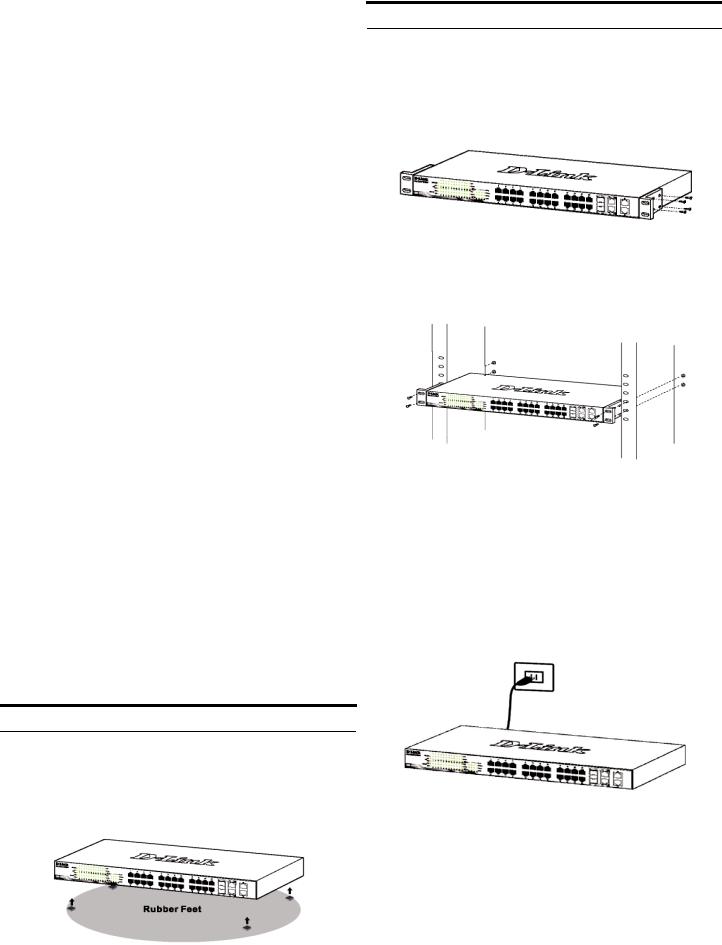
Para instalar el switch sobre una mesa o en un estante, debe fijar los pies de goma que se incluyen con el dispositivo en la base del mismo, uno en cada esquina. Deje suficiente espacio entre el dispositivo y los objetos que haya alrededor para la ventilación.
Figura 1. Fijar los pies de goma
Instalación en rack
El switch se puede montar en un rack EIA estándar de 19'', que se puede colocar en un armario de cableado junto a otros equipos. Para instalarlo, fije los ángulos de montaje en los laterales del switch (uno a cada lado)con los tornillos suministrados.
Figura 2. Fijar los ángulos de montaje
Luego, con los tornillos suministrados con el rack, monte el switch en el rack.
Figura 3. Instalar el switch en un rack estándar
Paso 3. Conexión del cable de alimentación AC
Ahora puede conectar el cable de alimentación AC a la parte posterior del switch y a una toma eléctrica (preferiblemente una que disponga de toma de tierra y protector de sobretensión).
Figura 4. Conectar el switch a una toma eléctrica
Corte del suministro eléctrico
Como precaución, en caso de corte del suministro eléctrico, el switch debería desenchufarse. Cuando se restablece el consumo eléctrico, puede volver a enchufarlo.
14
Opciones de gestión
El switch Web Smart de D-Link puede gestionarse a través de cualquier puerto del dispositivo usando la utilidad de gestión basada en web, o bien a través de cualquier PC usando la utilidad SmartConsole.
Si quiere gestionar solo un switch Web Smart de D-Link, la mejor opción es la utilidad de gestión basada en web. Cada switch debe tener asignada su propia dirección IP, que se usa para comunicarse con la utilidad de gestión basada en web o con un gestor de red SNMP, y el PC ha de tener una dirección IP en el mismo rango que el switch.
Sin embargo, si quiere gestionar varios switches Web Smart de D-Link, la mejor opción es la utilidad
SmartConsole. Con la utilidad SmartConsole, no necesita cambiar la dirección IP del PC y es fácil realizar la configuración inicial de varios switches Smart.
Vea las instrucciones detalladas que figuran a continuación sobre la utilidad de gestión basada en web y la utilidad
SmartConsole, Gestión de Telnet y gestión basada en SNMP.
Interfaz de gestión basada en web
Tras haber realizado la instalación física sin problemas, puede configurar el switch, controlar el panel de indicadores LED y visualizar las estadísticas gráficamente por medio de un navegador web, como Netscape Navigator (versión 6.2 o superior) o Microsoft® Internet Explorer (versión 5.0 o superior).
Para realizar la configuración web del dispositivo, necesita el equipo siguiente:
Un PC con una conexión Ethernet RJ-45.
Un cable Ethernet estándar.
Paso 1
Conecte el cable Ethernet a cualquiera de los puertos del panel delantero del switch y al puerto Ethernet del PC.
Figura 6. Conectar el cable Ethernet
Paso 2
Para iniciar sesión y configurar el switch a través de una conexión Ethernet, el PC debe tener una dirección IP en el mismo rango que el switch. Por ejemplo, si el switch tiene una dirección IP de 10.90.90.90, el PC debe tener una dirección IP de 10.x.y.z (donde x/y es un número entre 0 y 254 y z es un número entre 1 y 254), y una máscara de subred de 255.0.0.0.
Abra el navegador web y escriba http://10.90.90.90 (la dirección IP por defecto) en el campo de direcciones. Luego pulse <Intro>.
Figura 7. Introducir la dirección IP 10.90.90.90 en el navegador web
A la configuración web también se puede acceder a través de la utilidad SmartConsole. Abra la utilidad SmartConsole y haga doble clic sobre el switch, que figura en la lista de dispositivos. De este modo, se cargará la configuración web en el navegador web.
NOTA: La dirección IP por defecto del switch es 10.90.90.90, con una máscara de subred de 255.0.0.0 y un gateway por defecto de 0.0.0.0
Paso 3
Cuando aparezca la siguiente caja de entrada al sistema, escriba «admin» en el campo contraseña. Pulse OK para entrar en la ventana principal de configuración.
Figura 8. Ventana de autentificación del usuario
Paso 4
Antes de acceder a la gestión basada en web, el Asistente inteligente le guiará para configurar
15
 Loading...