


D-Link DGS-1224T
24-Port 10/100/1000Mbps
Gigabit Ethernet Switch + 2-Port mini GBIC Web-Smart Switch
Manual
Second Edition
Building Networks for People

TABLE OF CONTENT |
|
About This Guide................................................................................. |
1 |
Purpose ............................................................................................ |
1 |
Terms/Usage .................................................................................... |
1 |
Introduction.......................................................................................... |
3 |
Gigabit Ethernet Technology........................................................... |
3 |
Fast Ethernet Technology ................................................................ |
4 |
Switching Technology ..................................................................... |
5 |
VLAN (Virtual Local Area Network).............................................. |
6 |
Features............................................................................................ |
6 |
Unpacking and Installation .................................................................. |
9 |
Unpacking........................................................................................ |
9 |
Installation ....................................................................................... |
9 |
Rack Mounting .............................................................................. |
10 |
Connecting Network Cable............................................................ |
11 |
AC Power....................................................................................... |
11 |
Identifying External Components ...................................................... |
13 |
Front Panel..................................................................................... |
13 |
Rear Panel...................................................................................... |
14 |
Understanding LED Indicators .......................................................... |
15 |
Power and System LEDs ............................................................... |
15 |
Ports 1~24 Status LEDs ................................................................. |
16 |
Option Ports mini-GBIC 1 & mini-GBIC 2 mini-GBIC Status LEDs |
|
....................................................................................................... |
16 |
Configuration..................................................................................... |
17 |
i |
|

Installing the Web Management Utility......................................... |
17 |
Discovery List................................................................................ |
18 |
Monitor List ................................................................................... |
19 |
Device Setting................................................................................ |
21 |
Toolbar........................................................................................... |
22 |
Configuring the Switch .................................................................. |
23 |
Login.............................................................................................. |
24 |
Setup Menu.................................................................................... |
25 |
Configuring Setup Setting.............................................................. |
27 |
Port Settings............................................................................... |
27 |
VLAN Settings (Virtual Local Area Network) .......................... |
29 |
Trunk Setting ............................................................................. |
30 |
Mirror Setting............................................................................. |
31 |
IEEE 802.1P QoS Setting .......................................................... |
33 |
Spanning Tree Setting................................................................ |
33 |
SNMP Setting ............................................................................ |
35 |
Jumbo Frame Setting ................................................................. |
41 |
Device Status ............................................................................. |
42 |
Statistic....................................................................................... |
43 |
System Setting ........................................................................... |
44 |
Trap Setting................................................................................ |
46 |
Set Password .............................................................................. |
47 |
Backup Setting........................................................................... |
48 |
Reset Setting .............................................................................. |
48 |
Logout............................................................................................ |
49 |
ii |
|

Technical Specifications .................................................................... |
37 |
iii

ABOUT THIS GUIDE
Congratulations on your purchase of the DGS-1224T 24-Port 10/100/1000Mbps Gigabit Ethernet+2-Port Mini GBIC Web Smart Switch. This device integrates 1000Mbps Gigabit Ethernet, 100Mbps Fast Ethernet and 10Mbps Ethernet network capabilities in a highly flexible package.
Purpose
This guide discusses how to install and configure the DGS-1224T Web Smart Switch.
Terms/Usage
In this guide, the term “Switch” (first letter upper case) refers to your DGS-1224T Web Smart Switch, and “switch” (first letter lower case) refers to other Ethernet switches.
1

INTRODUCTION
This chapter describes the features of the DGS-1224T and some background information about Ethernet/Fast Ethernet/Gigabit Ethernet switching technology.
Gigabit Ethernet Technology
Gigabit Ethernet is an extension of IEEE 802.3 Ethernet utilizing the same packet structure, format, and support for CSMA/CD protocol, full duplex, flow control, and management objects, but with a tenfold increase in theoretical throughput over 100-Mbps Fast Ethernet and a hundredfold increase over 10-Mbps Ethernet. Since it is compatible with all 10-Mbps and 100-Mbps Ethernet environments, Gigabit Ethernet provides a straightforward upgrade without wasting a company’s existing investment in hardware, software, and trained personnel.
The increased speed and extra bandwidth offered by Gigabit Ethernet is essential to coping with the network bottlenecks that frequently develop as computers and their busses get faster and more users use applications that generate more traffic. Upgrading key components, such as your backbone and servers to Gigabit Ethernet can greatly improve network response times as well as significantly speed up the traffic between your subnets.
Gigabit Ethernet enables fast optical fiber connections to support video conferencing, complex imaging, and similar data-intensive applications. Likewise, since data transfers occur 10 times faster than Fast Ethernet, servers outfitted with Gigabit Ethernet NIC’s are able to perform 10 times the number of operations in the same amount of time.
In addition, the phenomenal bandwidth delivered by Gigabit Ethernet is the most cost-effective method to take advantage of today and
3

tomorrow’s rapidly improving switching and routing internetworking technologies. And with expected advances in the coming years in silicon technology and digital signal processing that will enable Gigabit Ethernet to eventually operate over unshielded twisted-pair (UTP) cabling, outfitting your network with a powerful 1000-Mbps- capable backbone/server connection creates a flexible foundation for the next generation of network technology products.
Fast Ethernet Technology
The growing importance of LANs and the increasing complexity of desktop computing applications are fueling the need for high performance networks. A number of high-speed LAN technologies have been proposed to provide greater bandwidth and improve client/server response times. Among them, 100BASE-T (Fast Ethernet) provides a non-disruptive, smooth evolution from the current 10BASE-T technology. The non-disruptive and smooth evolution nature, and the dominating potential market base, virtually guarantees cost-effective and high performance Fast Ethernet solutions.
100Mbps Fast Ethernet is a standard specified by the IEEE 802.3 LAN committee. It is an extension of the 10Mbps Ethernet standard with the ability to transmit and receive data at 100Mbps, while maintaining the CSMA/CD Ethernet protocol. Since the 100Mbps Fast Ethernet is compatible with all other 10Mbps Ethernet environments, it provides a straightforward upgrade and takes advantage of the existing investment in hardware, software, and personnel training.
4
Switching Technology
Another approach to pushing beyond the limits of Ethernet technology is the development of switching technology. A switch bridges Ethernet packets at the MAC address level of the Ethernet protocol transmitting among connected Ethernet or Fast Ethernet LAN segments.
Switching is a cost-effective way of increasing the total network capacity available to users on a local area network. A switch increases capacity and decreases network loading by dividing a local area network into different segments, which don’t compete with each other for network transmission capacity.
The switch acts as a high-speed selective bridge between the individual segments. The switch, without interfering with any other segments, automatically forwards traffic that needs to go from one segment to another. By doing this the total network capacity is multiplied, while still maintaining the same network cabling and adapter cards.
Switching LAN technology is a marked improvement over the previous generation of network bridges, which were characterized by higher latencies. Routers have also been used to segment local area networks, but the cost of a router, the setup and maintenance required make routers relatively impractical. Today switches are an ideal solution to most kinds of local area network congestion problems.
5

VLAN (Virtual Local Area Network)
A VLAN is a group of end-stations that are not constrained by their physical location and can communicate as if a common broadcast domain, a LAN. The primary utility of using VLAN is to reduce latency and need for routers, using faster switching instead. Other VLAN utility includes:
Security, Security is increased with the reduction of opportunity in eavesdropping on a broadcast network because data will be switched to only those confidential users within the VLAN.
Cost Reduction, VLANs can be used to create multiple broadcast domains, thus eliminating the need of expensive routers.
Port-based (or port-group) VLAN is the common method of implementing a VLAN, and is the one supplied in the Switch.
Features
24×10/100/1000Mbps Auto-negotiation Gigabit Ethernet ports
All RJ45 ports support auto MDI/MDIX, so there is no need to use cross-over cables or an up-link port
Half duplex transfer mode for connection speed 10Mbps and 100Mbps
Full duplex transfer mode for connection speed of 10Mbps, 100Mbps and 1000Mbsps
Gigabit Wire speed reception and transmission
Store-and-Forward switching scheme capability to support rate adaptation and ensure data integrity
6

Up to 8K unicast addresses entities per device, self-learning, and table aging
512KBytes packet buffer
Supports IEEE 802.3x flow control for full-duplex mode ports
Supports IEEE 802.1Q-based VLAN
Supports IEEE 802.1P-based QoS
Supports Port-trunking
Supports Port-mirroring
Supports Port-setting for Speed/Disable, Flow control and Port priority
Support Jumbo-frame setting
Supports IEEE 802.1D Spanning Tree protocol
Support Simple Network Management Protocol (SNMP)
Supports MIB for:
RFC1213 MIB II.
Private MIB.
Easy configuration via WEB Browser
Easy setting via Web Management Utility
Standard 19” Rack-mount size
7

UNPACKING AND INSTALLATION
This chapter provides unpacking and installation information for the Switch.
Unpacking
Open the shipping cartons of the Switch and carefully unpacks its contents. The carton should contain the following items:
One DGS-1224T Web Smart Switch
One AC power cord, suitable for your area’s electrical power connections
Four rubber feet to be used for shock cushioning
Screws and two mounting brackets
CD-Rom with Web Management Utility and User’s Guide
Quick Installation Guide
If any item is found missing or damaged, please contact your local reseller for replacement.
Installation
The site where you install the hub stack may greatly affect its performance. When installing, consider the following pointers:
Install the Switch in a fairly cool and dry place. See Technical Specifications for the acceptable temperature and humidity operating ranges.
Install the Switch in a site free from strong electromagnetic field generators (such as motors), vibration, dust, and direct exposure to sunlight.
9

Leave at least 10cm of space at the front and rear of the hub for ventilation.
Install the Switch on a sturdy, level surface that can support its weight, or in an EIA standard-size equipment rack. For information on rack installation, see the next section, Rack Mounting.
When installing the Switch on a level surface, attach the rubber feet to the bottom of each device. The rubber feet cushion the hub and protect the hub case from scratching.
Figure 1. Attach the adhesive rubber pads to the bottom
Rack Mounting
The switch can be mounted in an EIA standard-size, 19-inch rack, which can be placed in a wiring closet with other equipment. Attach the mounting brackets at the switch’s front panel (one on each side), and secure them with the provided screws.
Figure 2. Combine the Switch with the provided screws
10
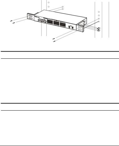
Then, use screws provided with the equipment rack to mount each switch in the rack.
Figure 3. Mount the Switch in the rack
Connecting Network Cable
The Switch supports 1000Mbps Gigabit Ethernet that runs in Autonegotiation mode and 10Mbps Ethernet or 100Mbps Fast Ethernet that runs both in half and full duplex mode and 1000Mbps Gigabit Ethernet runs in full duplex mode using four pair of Category 5 Cable.
These RJ-45 ports are Auto-MDI type port. The Switch can auto transform to MDI-II or MDI-X type, so you can just make an easy connection that without worrying if you are using a standard or crossover RJ45 cable.
AC Power
The Switch used the AC power supply 100-240V AC, 50-60 Hz. The power switch is located at the rear of the unit adjacent to the AC power connector and the system fan. The switch’s power supply will adjust to the local power source automatically and may be turned on without having any or all LAN segment cables connected.
11
IDENTIFYING EXTERNAL COMPONENTS
This chapter describes the front panel, rear panel, and LED indicators of the Switch.
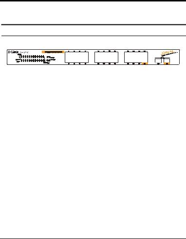
Front Panel
The figure below shows the front panels of the Switch.
Figure 4. Front panel of 24-port Gigabit Ethernet Switch
LED Indicator:
Comprehensive LED indicators display the status of the switch and the network (see the LED Indicators chapter below).
Gigabit Ethernet Ports (Port 1~24):
The Switch sixteen Gigabit twisted pair ports, supported auto negotiable 10/100/1000Mbps and auto MDI/MDIX crossover detection function, this function gives true “plug and play” capability, just need to plug-in the network cable to the hub directly and don’t care if the end node is NIC (Network Interface Card) or switch and hub. These ports can operate in half-duplex mode for 10/100Mbps and fullduplex mode for 10/100/1000Mbps.
Mini GBIC Ports
The Switch is equipped with two mini-GBIC ports, supported optional 1000BASE-SX/LX mini-GBIC module.
Note: When the port was set to “Forced Mode”, the Auto MDI/MDIX will be disabled.
13

Rear Panel
●
Reset button
Figure 5. Rear panel of the Switch
AC Power Connector:
This is a three-pronged connector that supports the power cord. Plug in the female connector of the provided power cord into this connector, and the male into a power outlet. Supported input voltages range from 100-240V AC at 50-60Hz.
Reset:
The Reset button is to reset all the setting back to the factory default.
Note: Be sure that you recorded the setting of your device, else all the setting will be erased when pressing the “Reset” button.
14
 Loading...