


 Loading...
Table of Contents |
D-Link Smart Managed Switch User Manual |
Table of Contents |
|
Table of Contents ............................................................................................................................................. |
i |
About This Guide............................................................................................................................................. |
1 |
Terms/Usage.................................................................................................................................................. |
1 |
Copyright and Trademarks ............................................................................................................................ |
1 |
Product Introduction ................................................................................................................................... |
2 |
DGS-1100-05V2............................................................................................................................................. |
2 |
Front Panel ................................................................................................................................................. |
2 |
Rear Panel.................................................................................................................................................. |
3 |
DGS-1100-05PDV2........................................................................................................................................ |
3 |
Front Panel ................................................................................................................................................. |
3 |
Rear Panel.................................................................................................................................................. |
4 |
DGS-1100-08V2............................................................................................................................................. |
4 |
Front Panel ................................................................................................................................................. |
4 |
Rear Panel.................................................................................................................................................. |
4 |
DGS-1100-08PV2 .......................................................................................................................................... |
5 |
Front Panel ................................................................................................................................................. |
5 |
Rear Panel.................................................................................................................................................. |
6 |
LED Indicators................................................................................................................................................ |
6 |
Hardware Installation .................................................................................................................................. |
8 |
Step 1: Unpacking.......................................................................................................................................... |
8 |
Step 2: Switch Installation.............................................................................................................................. |
8 |
Desktop or Shelf Installation....................................................................................................................... |
8 |
Wall-mount ................................................................................................................................................. |
8 |
Getting Started........................................................................................................................................... |
10 |
Management Options................................................................................................................................... |
10 |
Using the Web-based Management Interface ............................................................................................. |
10 |
Connecting to the Switch.......................................................................................................................... |
10 |
Accessing the Web-based Management Interface .................................................................................. |
10 |
Web-based Management............................................................................................................................. |
11 |
D-Link Network Assistant (DNA).................................................................................................................. |
11 |
Configuration ............................................................................................................................................. |
12 |
Web-based Management............................................................................................................................. |
12 |
Tool Bar > Save Menu ................................................................................................................................. |
13 |
Save Configuration................................................................................................................................... |
13 |
Tool Bar > Tool Menu .................................................................................................................................. |
13 |
Reboot System ......................................................................................................................................... |
13 |
Reset ........................................................................................................................................................ |
13 |
Firmware Backup and Upgrade................................................................................................................ |
13 |
Configuration Backup and Restore .......................................................................................................... |
14 |
Tool Bar > Online Help................................................................................................................................. |
14 |
Function Tree ............................................................................................................................................... |
14 |
Device Information.................................................................................................................................... |
15 |
System > System Information Settings > System Information................................................................. |
15 |
System > System Information Settings > IPv4 Interface.......................................................................... |
16 |
System > Port configuration > Port Settings ............................................................................................ |
16 |
System > Port Configuration > Jumbo Frame.......................................................................................... |
17 |
System > PoE > PoE System (DGS-1100-05PDV2/08PV2 only)............................................................ |
17 |
i |
|

Table of Contents |
D - Link Smart Managed Switch User Manual |
||
System > PoE > PoE Configuration (DGS-1100-05PDV2/08PV2 only) .................................................. |
18 |
||
System > PoE > PD Alive (DGS-1100-05PDV2/08PV2 only) |
.................................................................. |
20 |
|
Management > Password Access Control ............................................................................................... |
|
20 |
|
Management > SNMP > SNMP Global Settings...................................................................................... |
|
21 |
|
Management > SNMP > SNMP Community Table Settings.................................................................... |
|
22 |
|
Management > SNMP > SNMP Host Settings......................................................................................... |
|
22 |
|
Management > D-Link Discovery Protocol............................................................................................... |
|
23 |
|
L2 |
Features > FDB > Static FDB > Unicast Static FDB ........................................................................... |
|
23 |
L2 |
Features > FDB > Static FDB > Multicast Static FDB......................................................................... |
|
24 |
L2 |
Features > FDB > MAC Address Table Settings ................................................................................ |
|
24 |
L2 Features > FDB > MAC Address Table .............................................................................................. |
|
25 |
|
L2 Features > VLAN > 802.1Q VLAN ...................................................................................................... |
|
25 |
|
L2 Features > VLAN > Port-Based VLAN ................................................................................................ |
|
26 |
|
L2 Features > VLAN > Management VLAN ............................................................................................. |
|
27 |
|
L2 Features > VLAN > Asymmetric VLAN ............................................................................................... |
|
27 |
|
L2 |
Features > VLAN > Surveillance VLAN .............................................................................................. |
|
28 |
L2 Features > VLAN > Voice VLAN ......................................................................................................... |
|
29 |
|
L2 |
Features > Spanning Tree > STP Global Settings.............................................................................. |
|
30 |
L2 |
Features > Spanning Tree > STP Port Settings.................................................................................. |
|
31 |
L2 |
Features > Loopback Detection .......................................................................................................... |
|
32 |
L2 |
Features > Link Aggregation ............................................................................................................... |
|
33 |
L2 |
Features > L2 Multicast Control > IGMP Snooping > IGMP .................................Snooping Settings |
33 |
|
L2 |
Features > L2 Multicast Control > IGMP Snooping > IGMP ......................Snooping Group Settings |
34 |
|
QoS > 802.1p/DSCP Default Priority ....................................................................................................... |
|
34 |
|
QoS > Port Rate Limiting.......................................................................................................................... |
|
35 |
|
Security > Traffic Segmentation ............................................................................................................... |
|
36 |
|
Security > Storm Control .......................................................................................................................... |
|
36 |
|
Security > Port Security............................................................................................................................ |
|
37 |
|
OAM > Cable Diagnostics ........................................................................................................................ |
|
37 |
|
Monitoring > Statistics > Port Counters.................................................................................................... |
|
38 |
|
Monitoring > Mirroring Settings ................................................................................................................ |
|
38 |
|
Green > EEE ............................................................................................................................................ |
|
39 |
|
Ethernet Technology ..................................................................................................................................... |
|
40 |
|
Gigabit Ethernet Technology ....................................................................................................................... |
|
40 |
|
Fast Ethernet Technology............................................................................................................................ |
|
40 |
|
Switching Technology .................................................................................................................................. |
|
40 |
|
PoE Passthrough ......................................................................................................................................... |
|
41 |
|
Technical Specifications............................................................................................................................... |
|
42 |
|
Regulatory Statements.................................................................................................................................. |
|
44 |
|
ii
About This Guide |
D-Link Smart Managed Switch User Manual |
About This Guide
This guide provides step-by-step instructions on how install the D-Link DGS-1100- 05V2/05PDV2/08V2/08PV2 Smart Managed Switches, how to use the Web Utility, and how to perform webbased management functions.
Note: The model you have purchased may appear slightly different from the illustrations shown in the document. Refer to the Product Introduction and Technical Specification sections for detailed information about your switch, its components, network connections, and technical specifications.
This guide is mainly divided into four parts:
1.Hardware Installation: Step-by-step hardware installation procedures.
2.Getting Started: A startup guide for basic switch installation and settings.
3.Web Configuration: Information about the function descriptions and configuration settings via Web.
Terms/Usage
In this guide, the term “Switch” (first letter capitalized) refers to the Smart Managed Switch, and “switch” (first letter lower case) refers to other Ethernet switches. Some technologies refer to terms “switch”, “bridge” and “switching hubs” interchangeably, and both are commonly accepted for Ethernet switches.
A NOTE indicates important information that helps a better use of the device.
A CAUTION indicates potential property damage or personal injury.
Copyright and Trademarks
Information in this document is subjected to change without notice. © 2020 D-Link Corporation. All rights reserved.
Reproduction in any manner whatsoever without the written permission of D-Link Corporation is strictly forbidden.
Trademarks used in this text: D-Link and the D-LINK logo are trademarks of D-Link Corporation; Microsoft and Windows are registered trademarks of Microsoft Corporation.
Other trademarks and trade names may be used in this document to refer to either the entities claiming the marks and names or their products. D-Link Corporation disclaims any proprietary interest in trademarks and trade names other than its own.
1
1 Product Introduction |
D-Link Smart Managed Switch User Manual |
1 Product Introduction
Thank you and congratulations on the purchase of your new D-Link Smart Managed Switch.
D-Link's next generation Smart Managed switch series blends plug-and-play simplicity with exceptional value and reliability for small and medium-sized business (SMB) networking. All models are housed in a robust metal case with easy-to-view front panel diagnostic LEDs.
Flexible Port Configurations. The DGS-1100 series is the new generation of Smart Managed Switches, featuring 5 to 8 10/100/1000 Mbps.
D-Link Green Technology. The DGS-1100 Series features D-Link Green Technology which helps conserve power without sacrificing operational performance. Using IEEE 802.3az Energy Efficient Ethernet (EEE), the DGS-1100 Series saves power by automatically putting inactive ports into a sleep mode.
Extensive Layer 2 Features. Designed as comprehensive L2 devices, these switches support a variety of functions such as FDB, VLAN, Spanning Tree, and Loopback Detection to enhance performance and network resilience.
Traffic Segmentation and QoS. The switches support 802.1Q VLAN standard tagging to enhance network security and performance. The switches also support 802.1p priority queues, enabling users to run bandwidth-sensitive applications such as streaming multimedia by prioritizing that traffic in network. The Surveillance VLAN will place the video traffic from pre-defined IP surveillance devices to an assigned VLAN with higher priority, so it can be separated from normal data traffic.
Network Security. Storm Control can help to keep the network from being overwhelmed by abnormal traffic. Meanwhile, Port Security provides administrators with an additional layer of security to prevent unauthorized users from accessing the network.
Versatile Management. The DGS-1100-05V2/05PDV2/08V2/08PV2 feature an intuitive, web-based management interface that allows administrators to remotely control their network down to the port level. The D-Link Network Assistant (DNA) easily allows administrators to discover multiple D-Link Smart Managed Switches within the same L2 network segment and display them on-screen for instant access. With this utility, users do not need to change the IP address of their PC. This allows for simultaneous configuration and basic setup of all discovered devices, including password changes and firmware upgrades.
DGS-1100-05V2
5-Port 10/100/1000Mbps Smart Managed Switch.
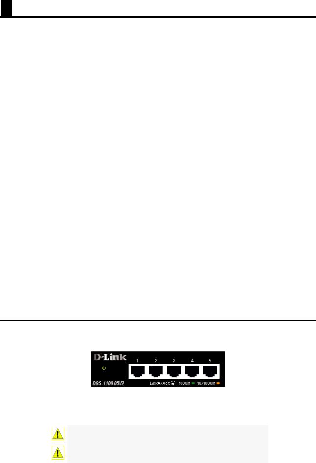
Front Panel
Figure 1.1 – DGS-1100-05V2 Front Panel
Power LED: The Power LED lights up when the Switch is connected to a power source. Link/Act/Speed LED (Ports 1-5): 10/100/1000 Mbps ports to connect Ethernet devices to the switch.
CAUTION: The equipment power supply cord shall be connected to a socket-outlet with earthing connection.
Le cordon d'alimentation de l'équipement doit être branché sur une prise de courant dotée d'une connexion à la terre.
2
1 Product Introduction |
D-Link Smart Managed Switch User Manual |
Rear Panel
Figure 1.2 – DGS-1100-05V2 Rear Panel
Power: Input for a 5V/1A AC adapter.
Reset: Press the Reset button for 1 to 5 seconds to reboot the Switch. Press the Reset button for 6 to10 seconds to reset the Switch back to the default settings. The LED will light up solid amber for 2 seconds. When pressing the Reset button for longer than 10 seconds, the device will enter loader mode and the LED will light up solid green for 2 seconds. If the device cannot reboot, it will automatically enter loader mode. Alternatively, you can press Reset to power up the device and enter loader mode.
Kensington Lock: This is used to attach a physical Kensington security lock. GND: This is used to connect the Switch to ground.
DGS-1100-05PDV2
2-Port 10/100/1000Mbps PoE and 3-Port 10/100/1000Mbps with 1 PD port Smart Managed Switch.
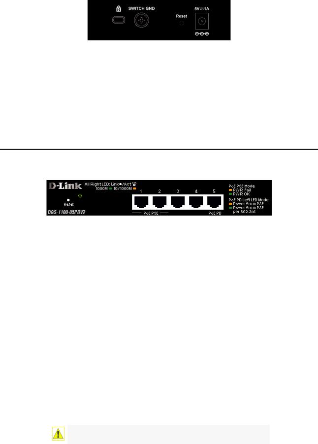
Front Panel
Figure 1.3 – DGS-1100-05PDV2 Front Panel
Power LED: The Power LED lights up when the Switch is connected to a power source. If the Power LED is Blinking, PoE Pass Through is Off.
Link/Act/Speed LED (Ports 1-5):
Flashing: Indicates a network link through the corresponding port.
Blinking: Indicates that the Switch is either sending or receiving data to the port. Green: Indicates that the port is running at 1000M.
Amber: Indicates that the port is running at 10/100M.
Light off: No link.
PoE PSE LED (Port 1-2):
Solid Green: PD device insert and power feeding. Solid Amber: PD device insert but failure occurs. Light off: No PD device insert.
PoE PD (Port 5):
Solid Green: Receiving power from PSE per 802.3at. Solid Amber: Receiving power from PSE per PSE.
Light off: No link.
Reset: Press the Reset button for 1 to 5 seconds to reboot the Switch. Press the Reset button for 6 to10 seconds to reset the Switch back to the default settings. The LED will light up solid amber for 2 seconds. When pressing the Reset button for longer than 10 seconds, the device will enter loader mode and the LED will light up solid green for 2 seconds. If the device cannot reboot, it will automatically enter loader mode. Alternatively, you can press Reset to power up the device and enter loader mode.
CAUTION: This equipment can be connected only to PoE networks without routing to the outside plant.
3
1 Product Introduction |
D-Link Smart Managed Switch User Manual |
L’équipement est conçu pour une installation dans un bâtiment et ne doit pas être connecté à des réseaux exposés (installations extérieures), notamment des environnements de campus, et l’ITE doit être connecté uniquement à des réseaux PoE sans acheminement vers une installation extérieure." ou équivalent.
CAUTION: This unit is supplied by POE through an UL Listed ITE.
Cet appareil est fourni par POE via un ITE répertorié UL.
Rear Panel
Figure 1.4 – DGS-1100-05PDV2 Rear Panel
Power: Use RJ45 to connect the PD port (port 5) and Power over Ethernet Adapter Kit. Kensington Lock: This is used to attach a physical Kensington security lock.
GND: This is used to connect the Switch to ground.
NOTE: The power budget is 18 Watts with 802.3at and 8 Watts with
802.3af for DGS-1100-05PDV2.
DGS-1100-08V2
8-Port 10/100/1000Mbps Smart Managed Switch.
Front Panel
Figure 1.5 – DGS-1100-08V2 Front Panel
Power LED: The Power LED lights up when the Switch is connected to a power source. Link/Act/Speed LED (Ports 1-8): 10/100/1000 Mbps ports to connect Ethernet devices to the switch.
CAUTION: The equipment power supply cord shall be connected to a socket-outlet with earthing connection.
Le cordon d'alimentation de l'équipement doit être branché sur une prise de courant dotée d'une connexion à la terre.
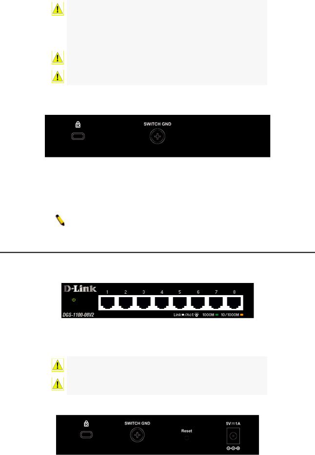
Rear Panel
Figure 1.6 – DGS-1100-08V2 Rear Panel
4

1 Product Introduction |
D-Link Smart Managed Switch User Manual |
Power: Input for a 5V/1A AC adapter.
Reset: Press the Reset button for 1 to 5 seconds to reboot the Switch. Press the Reset button for 6 to10 seconds to reset the Switch back to the default settings. The LED will light up solid amber for 2 seconds. When pressing the Reset button for longer than 10 seconds, the device will enter loader mode and the LED will light up solid green for 2 seconds. If the device cannot reboot, it will automatically enter loader mode. Alternatively, you can press Reset to power up the device and enter loader mode.
Kensington Lock: This is used to attach a physical Kensington security lock. GND: This is used to connect the Switch to ground.
DGS-1100-08PV2
8-Port 10/100/1000Mbps PoE Smart Managed Switch.
Front Panel
Figure 1.7 – DGS-1100-08PV2 Front Panel
Power LED: The Power LED lights up when the Switch is connected to a power source.
Reset: Press the Reset button for 1 to 5 seconds to reboot the Switch. Press the Reset button for 6 to10 seconds to reset the Switch back to the default settings. The LED will light up solid amber for 2 seconds. When pressing the Reset button for longer than 10 seconds, the device will enter loader mode and the LED will light up solid green for 2 seconds. If the device cannot reboot, it will automatically enter loader mode. Alternatively, you can press Reset to power up the device and enter loader mode.
Link/Act/Speed LED (Ports 1-8):
Flashing: Indicates a network link through the corresponding port.
Blinking: Indicates that the Switch is either sending or receiving data to the port. Green: Indicates that the port is running at 1000M.
Amber: Indicates that the port is running at 10/100M.
Light off: No link.
PoE MAX. LED:
Light up: Indicates the power output to PDs is over 57W. No additional PDs can be powered for safety consideration.
Blinking: Indicates if the user unplugged certain PDs and made the PoE power budget left over 7W, the PoE MAX LED will blink 5 seconds.
Light off: Indicates the power budget is using less than 57W.
PoE LED (Ports 1-8):
Green: Indicates the PoE powered device (PD) is connected and the port supplies power successfully.
Red: The PoE port has failed, possibly due to:
1.PoE total power budget shortage.
2.Over current: Exceeds the power current of powered device's classification.
3.Short circuit: Short circuit has been performed on a powered device.
Light off: Indicates no Powered Device (PD) connected.
PoE Mode LED (Port 1-8):
Solid Green: PD device insert and power feeding.
Solid Amber: PD device insert but failure occurs.
Light off: No PD device insert.
5
1 Product Introduction |
D-Link Smart Managed Switch User Manual |
CAUTION: The equipment power supply cord shall be connected to a socket-outlet with earthing connection.
Le cordon d'alimentation de l'équipement doit être branché sur une prise de courant dotée d'une connexion à la terre.
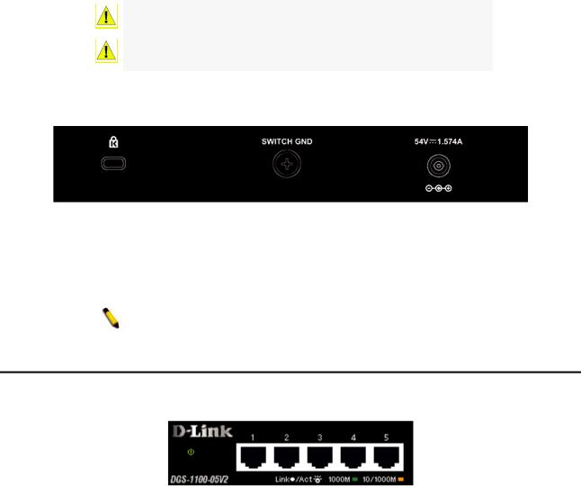
Rear Panel
Figure 1.8 – DGS-1100-08PV2 Rear Panel
Power: Input for a 54V/1.574A AC adapter.
Kensington Lock: This is used to attach a physical Kensington security lock.
GND: This is used to connect the Switch to ground.
NOTE: The power budget is 64 Watts for DGS-1100-08P.
LED Indicators
The Switches feature LED indicators for Power and Link/Act for each port. The following shows the LED indicators for the DGS-1100-05V2/05PDV2/08V2/08PV2 switches along with an explanation of each indicator.
Figure 1.9 –LED Indicators on DGS-1100 series
Location |
Indicator LED |
Color |
Status |
Description |
|
|
|
|
|
|
|
|
Solid Light |
The device is powered on. |
|
|
|
|
|
|
Power |
Green |
Blinking |
PoE Pass Through Off (DGS-1100- |
|
05PDV2 only) |
|||
|
|
|
|
|
|
|
|
Light off |
The device is powered off. |
|
|
|
|
|
Per Device |
|
|
|
When the power output to PDs is over |
|
|
Solid Light |
57W. No additional PDs can be |
|
|
PoE Max. |
|
|
powered for safety consideration. |
|
|
|
If the user unplugged certain PDs and |
|
|
(Only DGS-1100- |
Red |
Blinking |
made the PoE power budget left over |
|
08PV2) |
|
|
7W, the PoE MAX LED will blink 5 |
|
|
|
|
seconds. |
|
|
|
Light off |
When the power budget is using less |
|
|
|
the 57W. |
|
|
|
|
|
|
LED Per |
|
|
Solid Green |
Indicates there is a 1000 Mbps |
10/100/1000 |
Link/Act/Speed |
Green/Amber |
|
connection on this port. |
Blinking |
Indicates data is being processed on |
|||
Mbps Port |
|
|
Green |
this port at 1000 Mbps. |
|
|
|
6
1 Product Introduction |
|
|
D-Link Smart Managed Switch User Manual |
|||
|
|
|
|
|
|
|
|
|
|
|
Solid Amber |
Indicates there is a 10/100 Mbps |
|
|
|
|
|
connection on this port. |
|
|
|
|
|
|
Blinking |
Indicates data is being processed on |
|
|
|
|
|
Amber |
this port at 10/100 Mbps. |
|
|
|
|
|
Light off |
Indicates there is no active link on this |
|
|
|
|
|
port. |
|
|
|
|
|
|
|
|
|
|
|
|
|
Solid Green |
PD device insert and power feeding. |
|
|
|
|
|
|
|
|
|
|
|
|
|
PD device insert but failure occurs. |
|
|
LED Per PoE Port |
PoE Status |
Green/Amber |
Solid Amber |
(PSE can’t provide power to PD due to |
|
|
|
|
|
|
PD error or power budget is not |
|
|
|
|
|
|
enough.) |
|
|
|
|
|
Light off |
No PD device inserts. |
|
|
|
|
|
|
|
|
|
|
|
|
Solid Green |
Receiving power from PSE per 802.3at |
|
|
LED Per PD Port |
|
|
|
|
|
|
|
|
Solid Amber |
Receiving power from PSE per PSE. |
|
|
|
(DGS-1100- |
PD Status |
Green/Amber |
|
||
|
05PDV2 only) |
|
|
|
|
|
|
|
|
Light off |
No link. |
|
|
|
|
|
|
|
||
|
|
|
|
|
|
|
7
2 Hardware Installation |
D-Link Smart Managed Switch User Manual |
2 Hardware Installation
This chapter provides unpacking and installation information for your D-Link DGS-1100- 05V2/05PDV2/08V2/08PV2 Smart Managed Switch.
Step 1: Unpacking
Open the shipping carton and carefully unpack its contents. Please consult the packing list below to make sure all items are present and undamaged.
One DGS-1100-05V2/05PDV2/08V2/08PV2 Smart Managed Switch
One AC external power adapter
Four rubber feet
Wall-mount kit
Quick Installation Guide CD (User manual)
If any item is found missing or damaged, please contact the local reseller for replacement.
Step 2: Switch Installation
For safe switch installation and operation, it is recommended to you:
Visually inspect the power cord to see that it is secured fully to the AC power connector. Make sure that there is proper heat dissipation and adequate ventilation around the switch. Do not place heavy objects on the switch.
Desktop or Shelf Installation
The DGS-1100 series switches come with a strip of four adhesive rubber pads that can be placed on the bottom of the device to prevent the device from damaging the desktop or shelf it is places on. To attach the rubber pads, simply remove them from the adhesive strip and stick one pad on each corner on the bottom panel of the Switch.
Figure 2.1 – Attach the adhesive rubber pads to the bottom
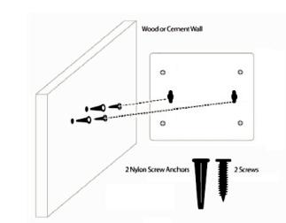
Wall-mount
The Switch can be mounted on a wall. Two mounting slots are provided on the bottom of the switch for this purpose.
Please refer to the instructions below on how to complete the wall-mounting process.
Mounting on a cement wall
Step 1: Drill two holes that align with the keyholes on the back of the Switch in the wall where you want to mount the device, and place the two indluded nylon screw anchors into the drilled holes.
Step 2: Drive the included screws into the nylon screw anchors.
Step 3: Hook the mounting keyholes on the back of the Switch onto the screws to secure the device to the wall.
Mounting on a wood wall
Step 1: Drive the included screws into a wood wall.
8
2 Hardware Installation |
D-Link Smart Managed Switch User Manual |
Step 2. Hook the mounting keyholes on the back of the Switch onto the screws to secure the device to the wall.
Figure 2.2 – Wall mount installation
Metal screw (M7 type; Length 16 mm, Number of screws *2) for DGS-1100-05V2/05PDV2/08V2/08PV2 Vis métallique (type M7 ; longueur 16 mm, nombre de vis *2) pour DGS-1100-05V2/05PDV2/08V2/08PV2
9
3 Getting Started |
D-Link Smart Managed Switch User Manual |
3 Getting Started
This chapter introduces the management interface of D-Link Smart Managed Switch.
Management Options
The D-Link Smart Managed Switch can be managed through any port on the device by using the web-based management interface, or the D-Link Network Assistant (DNA).
Each switch must be assigned its own IP address, which is used for communication with the web-based management interface or a SNMP network manager. The PC should have an IP address in the same range as the Switch. Each Switch allows up to four users to access the web-based management interface concurrently.
However, if you want to manage multiple D-Link Smart Managed Switches, the D-Link Network Assistant (DNA) is a more convenient choice. By using the D-Link Network Assistant (DNA), you do not need to change the IP address of your PC, making it easier to simultaneously initialize multiple D-Link Managed Switches.
Please refer to the following installation instructions for the Web interface and the D-Link Network Assistant (DNA).
Using the Web-based Management Interface
After successfully installing the Switch, you can configure and monitor the Switch through the web-based management tool using any compatible web browser such as Internet Explorer, Google Chrome, Firefox, Opera, or Safari.
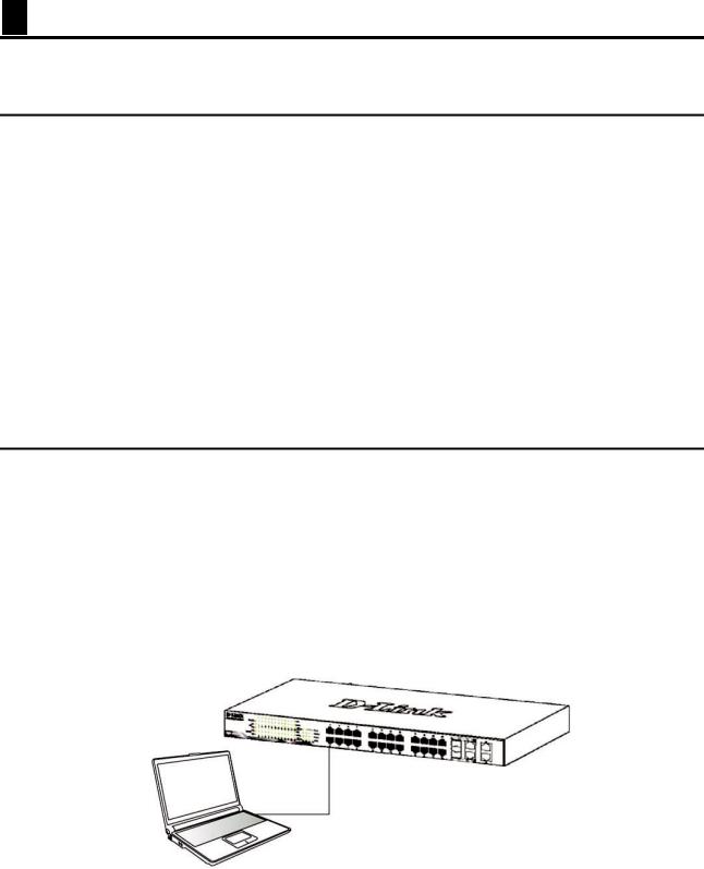
Connecting to the Switch
The access the web interface you will need the following equipment:
1.A PC with a RJ45 Ethernet port.
2.A standard Ethernet cable
Connect on end of the Ethernet cable to any of the ports on the front panel of the Switch and connect the other end of Ethernet cable to the Ethernet port on the PC.
Figure 3.1 – Connected Ethernet cable
Accessing the Web-based Management Interface
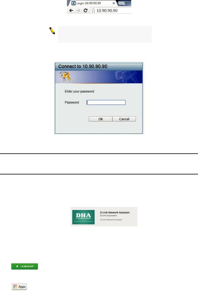
In order to access the management interface, the PC must have an IP address in the same subnet as the Switch. For example, if the Switch has an IP address of 10.90.90.90, the PC should have an IP address of 10.x.y.z (where x/y is a number between 0 ~ 254 and z is a number between 1 ~ 254), and a subnet mask of 255.0.0.0. To launch the web interface, simply open any compatible web browser and enter 10.90.90.90 (the factory-default IP address) in the address bar. Then press <Enter>.
10
3 Getting Started |
D-Link Smart Managed Switch User Manual |
Figure 3.2 –Enter the IP address 10.90.90.90 in the web browser
NOTE: The Switch’s factory default IP address is 10.90.90.90 with a subnet mask of 255.0.0.0 and a default gateway of 0.0.0.0.
This will automatically load the web configuration in your web browser.
When prompted to log in, enter the default password admin and press ok to continue.
Figure 3.3 – Logon Dialog Box
Web-based Management
Please refer to Chapter 4 Configuration for detailed instructions.
D-Link Network Assistant (DNA)
D-Link Network Assistant (DNA) is a program that is used to discover switches which are in the same Layer 2 network segment as your PC. You can download the DNA App from the Chrome web store and install it in a Chrome web browser.
1.Go to the Chrome web store at: https://chrome.google.com/webstore, and search the store for Network Assistant.
Figure 3.4 – D-LINK Network Assistant
2.Click ‘ADD TO CHROME’ button on the right hand side of the search results.
3.Click ‘Add app’ button in the pop-up window to install the D-Link Network Assistant in Chrome.
4.When the installation process has finished:
(Option 1) Click the ‘LAUNCH APP’ button in the upper-right corner of the window to start DNA.
(Option 2) Click the ‘Apps’ icon in the upper-left corner of the Chrome browser and click the DNA icon to start the app.
11
4 Configuration |
D-Link Smart Managed Switch User Manual |
4 Configuration
The features and functions of the D-Link Smart Managed Switch can be configured through the web-based management interface.
Web-based Management
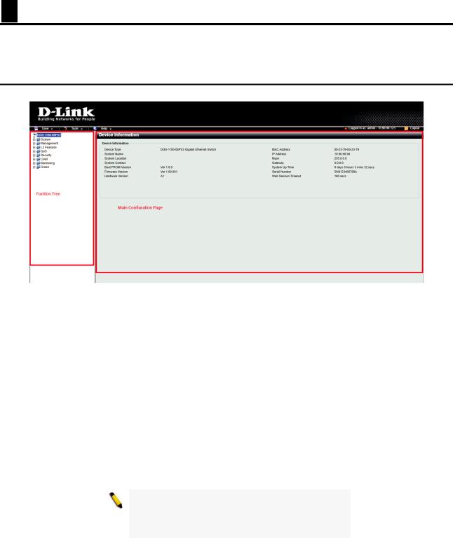
After a successful login you will see the screen below:
Figure 4.1 – Web-based Management
The three main areas are the Tool Bar on top, the Function Tree on the left, and the Main Configuration Screen.
The Tool Bar provides a quick and convenient way for accessing essential functions such as firmware upgrades and basic settings.
Clicking on a section or subsection in the function tree will display all the settings of that section in the main configuration screen. The main configuration screen will show the current status of your Switch by clicking the model name on top of the function tree.
In the upper-right corner of the screen the username and current IP address will be displayed.
Under the username is the Logout button. Click this to end this session.
NOTE: If you close the web browser without clicking the Logout button first, then it will be seen as an abnormal exit and the login session will still be occupied.
By clicking on the D-Link logo in the upper-left corner of the screen you will be redirected to the local D-Link website.
12

4 Configuration |
D-Link Smart Managed Switch User Manual |
Tool Bar > Save Menu
The Save Menu provides Save Configuration and Save Log functions.
Figure 4.2 – Save Menu
Save Configuration
By clicking Apply, the current device configuration will be saved on the device’s flash memory.
Figure 4.3 – Save Configuration
Tool Bar > Tool Menu
The Tool Menu provides basic functions such as Reset, Reset System, Reboot Device, Configuration Backup and Restore, Firmware Backup and Upgrade.
Figure 4.4 – Tool Menu
Reboot System
This option provides a safe way to reboot the system. Click Yes or No to decide to save the settings does this really reset to factory default settings or does it just discard the most recent unsaved changes. Click Reboot to restart the switch.
Figure 4.5 – Tool Menu > Reboot System
Reset
Provide a safe reset option for the Switch. Depending on the chosen reset option, some or all configuration settings stored in the device’s flash memory will be reset to factory default.
Figure 4.6 – Tool Menu > Reset
Select a suitable reset option and click Apply to make the configurations take effect.
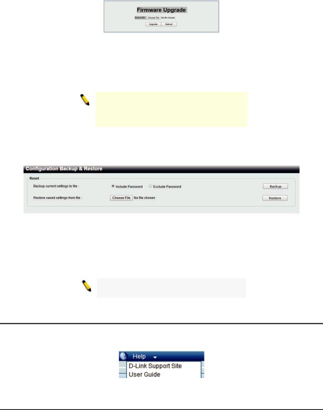
Firmware Backup and Upgrade
This functions allows you to create a backup of the device’s current firmware, or upgrade the firmware using a compatible firmware file.
Figure 4.7 – Tool Menu > Firmware Backup and Upgrade
13
4 Configuration |
D-Link Smart Managed Switch User Manual |
Click Backup to save the firmware to your disk.
Click Upgrade to upgrade the firmware. After clicking, the device will enter boot-loader mode and the following page will be displayed:
Figure 4.8 – Tool Menu > Firmware Backup and Upgrade - Upgrade
Click Choose File to browse for a compatible firmware file on your hard drive.
Click Upgrade to update the device’s firmware using the selected firmware file.
Click Reboot to cancel the firmware upgrade and reboot the device.
NOTE: Do not disconnect the PC or remove the power cord from device until the upgrade completes. The Switch may crash if the firmware update is interrupted.
Configuration Backup and Restore
Allow the current configuration settings to be saved to a file, and if necessary, you can restore the configuration settings from this file.
Figure 4.9 – Tool Menu > Configure Backup and Restore
Backup current settings to file: Specify to back up the current settings of the Switch with or without the password, and click Backup.
Restore saved settings from file: Click Choose File to browse your inventories for a saved backup settings file. And click Restore to backup settings file you want to restore.
Note: Switch will reboot after restore, and all current configurations will be overwritten.
Tool Bar > Online Help
The Online Help provides two ways of online support: D-Link Support Site will lead you to the D-Link website where you can find online resources such as updated firmware images; User Guide can offer an immediate reference for the feature definition or configuration guide.
Figure 4.10 – Online Help
Function Tree
All configuration options of the switch are accessed through the function menu on the left side of the screen. Click on the setup item that you want to configure. The following sections provide a more detailed description of each feature and function.
14
Loading...