


 Loading...
DGS-1100 MP/MPP Series Switch Web UI Reference Guide
Information in this document is subject to change without notice. © 2015 D-Link Corporation. All rights reserved.
Reproduction in any manner whatsoever without the written permission of D-Link Corporation is strictly forbidden.
Trademarks used in this text: D-Link and the D-Link logo are trademarks of D-Link Corporation; Microsoft and Windows are registered trademarks of Microsoft Corporation.
Other trademarks and trade names may be used in this document to refer to either the entities claiming the marks and names or their products. D-Link Corporation disclaims any proprietary interest in trademarks and trade names other than its own.
FCC Warning
This equipment has been tested and found to comply with the limits for a Class A digital device, pursuant to Part 15 of the FCC Rules. These limits are designed to provide reasonable protection against harmful interference when the equipment is operated in a commercial environment. This equipment generates, uses, and can radiate radio frequency energy and, if not installed and used in accordance with this user’s guide, may cause harmful interference to radio communications. Operation of this equipment in a residential area is likely to cause harmful interference in which case the user will be required to correct the interference at his own expense.
CE Mark Warning
This is a Class A product. In a domestic environment, this product may cause radio interference in which case the user may be required to take adequate measures.
Warnung!
Dies ist ein Produkt der Klasse A. Im Wohnbereich kann dieses Produkt Funkstoerungen verursachen. In diesem Fall kann vom Benutzer verlangt werden, angemessene Massnahmen zu ergreifen.
Precaución!
Este es un producto de Clase A. En un entorno doméstico, puede causar interferencias de radio, en cuyo case, puede requerirse al usuario para que adopte las medidas adecuadas.
Attention!
Ceci est un produit de classe A. Dans un environnement domestique, ce produit pourrait causer des interférences radio, auquel cas l`utilisateur devrait prendre les mesures adéquates.
Attenzione!
Il presente prodotto appartiene alla classe A. Se utilizzato in ambiente domestico il prodotto può causare interferenze radio, nel cui caso è possibile che l`utente debba assumere provvedimenti adeguati.
VCCI Warning
May, 2015
ii

DGS-1100 MP/MPP Series Switch Web UI Reference Guide
Table of Contents
1. |
Introduction ................................................................................................................................................................... |
1 |
|
Audience ............................................................................................................................................................................ |
1 |
|
Standard Mode and Surveillance Mode............................................................................................................................. |
1 |
|
Other Documentation......................................................................................................................................................... |
1 |
|
Conventions ....................................................................................................................................................................... |
1 |
|
Notes, Notices, and Cautions ............................................................................................................................................ |
2 |
2. |
Product Introduction..................................................................................................................................................... |
3 |
|
DGS-1100-10MP ............................................................................................................................................................... |
4 |
|
Front Panel ................................................................................................................................................................... |
4 |
|
Rear Panel.................................................................................................................................................................... |
4 |
|
DGS-1100-10MPP ............................................................................................................................................................. |
6 |
|
Front Panel ................................................................................................................................................................... |
6 |
|
Rear Panel.................................................................................................................................................................... |
6 |
|
DGS-1100-26MP ............................................................................................................................................................... |
8 |
|
Front Panel ................................................................................................................................................................... |
8 |
|
Rear Panel.................................................................................................................................................................... |
9 |
|
DGS-1100-26MPP ........................................................................................................................................................... |
10 |
|
Front Panel ................................................................................................................................................................. |
10 |
|
Rear Panel.................................................................................................................................................................. |
11 |
3. |
Hardware Installation.................................................................................................................................................. |
12 |
|
Step 1: Unpacking............................................................................................................................................................ |
12 |
|
Packing Contents........................................................................................................................................................ |
12 |
|
Step 2: Switch Installation................................................................................................................................................ |
12 |
|
Desktop or Shelf Installation....................................................................................................................................... |
12 |
|
Rack Installation ......................................................................................................................................................... |
12 |
|
Step 3: Plugging in the AC Power Cord........................................................................................................................... |
14 |
|
Power Failure.............................................................................................................................................................. |
14 |
|
Grounding the Switch ................................................................................................................................................. |
14 |
4. |
Web-based Switch Configuration.............................................................................................................................. |
16 |
|
Management Options....................................................................................................................................................... |
16 |
|
Connecting using the Web User Interface ....................................................................................................................... |
16 |
|
Logging onto the Web User Interface .............................................................................................................................. |
17 |
|
Smart Wizard ................................................................................................................................................................... |
18 |
|
Web User Interface .......................................................................................................................................................... |
22 |
|
Areas of the User Interface......................................................................................................................................... |
23 |
5. |
Surveillance Overview ................................................................................................................................................ |
24 |
|
Surveillance Topology...................................................................................................................................................... |
24 |
|
Enabling and Disabling PoE ....................................................................................................................................... |
27 |
|
Device Information ........................................................................................................................................................... |
28 |
6. |
Port Information .......................................................................................................................................................... |
29 |
|
Group Details ................................................................................................................................................................... |
31 |
7. |
IP-Camera Information................................................................................................................................................ |
33 |
8. |
NVR Information.......................................................................................................................................................... |
35 |
|
|
iii |

|
DGS-1100 MP/MPP Series Switch Web UI Reference Guide |
|
9. |
PoE Information........................................................................................................................................................... |
37 |
10. |
PoE Scheduling........................................................................................................................................................... |
39 |
11. |
Time .............................................................................................................................................................................. |
41 |
|
Clock Settings .................................................................................................................................................................. |
41 |
|
SNTP Settings ................................................................................................................................................................. |
41 |
12. |
Surveillance Settings.................................................................................................................................................. |
43 |
13. |
Surveillance Log.......................................................................................................................................................... |
46 |
14. |
Health Diagnostic........................................................................................................................................................ |
47 |
15. |
Save and Tools............................................................................................................................................................ |
48 |
|
Firmware Information ....................................................................................................................................................... |
48 |
|
Firmware Upgrade & Backup........................................................................................................................................... |
48 |
|
Firmware Upgrade from HTTP ................................................................................................................................... |
48 |
|
Firmware Backup to HTTP ......................................................................................................................................... |
49 |
|
Configuration Restore & Backup ..................................................................................................................................... |
50 |
|
Configuration Restore from HTTP .............................................................................................................................. |
50 |
|
Configuration Backup to HTTP................................................................................................................................... |
50 |
|
Reset................................................................................................................................................................................ |
51 |
|
Reboot System ................................................................................................................................................................ |
51 |
16. |
Appendix A - Ethernet Technology ........................................................................................................................... |
53 |
|
Gigabit Ethernet Technology ........................................................................................................................................... |
53 |
|
Fast Ethernet Technology................................................................................................................................................ |
53 |
|
Switching Technology ...................................................................................................................................................... |
53 |
17. |
Appendix B - Technical Specifications..................................................................................................................... |
55 |
|
Hardware Specifications .................................................................................................................................................. |
55 |
|
Key Components / Performance ................................................................................................................................ |
55 |
|
Port Functions............................................................................................................................................................. |
55 |
|
Physical & Environment.............................................................................................................................................. |
55 |
|
Emission (EMI) Certifications...................................................................................................................................... |
55 |
|
Safety Certifications.................................................................................................................................................... |
55 |
|
Features ........................................................................................................................................................................... |
55 |
|
L2 Features................................................................................................................................................................. |
55 |
|
L2 Multicasting............................................................................................................................................................ |
55 |
|
VLAN........................................................................................................................................................................... |
55 |
|
Quality of Service (QoS) ............................................................................................................................................. |
56 |
|
Security....................................................................................................................................................................... |
56 |
|
Management............................................................................................................................................................... |
56 |
|
Power Saving.............................................................................................................................................................. |
56 |
|
Surge Protection ......................................................................................................................................................... |
56 |
18. |
Appendix C – Rack mount Instructions.................................................................................................................... |
57 |
iv

D-Link DGS-1100 MP/MPP Series Switch User Manual
1.Introduction
This manual’s command descriptions are based on the software release 1.00. The commands listed here are the subset of commands that are supported by the DGS-1100 MP/MPP Series switch.
Audience
This reference manual is intended for network administrators and other IT networking professionals responsible for managing the switch by using the Web User Interface (Web UI). The Web UI is the secondary management interface to the DGS-1100 MP/MPP Series switch, which will be generally be referred to simply as ‘the switch’ within this manual. This manual is written in a way that assumes that you already have the experience and knowledge of Ethernet and modern networking principles for Local Area Networks.
Standard Mode and Surveillance Mode
The DGS-1100 MP/MPP Series switches support Standard Mode and Surveillance Mode Web UI types. Standard Mode is used to manage the network and system elements of the switch. Surveillance Mode is a dedicated user interface designed for monitoring and managing the surveillance and IP security devices on your network.
To switch between the two types of interfaces, you can re-run the Smart Wizard that is presented when you access the web interface of the device. For more information, please refer to the Web UI Interface Guide for the appropriate mode.
Other Documentation
The documents below are a further source of information in regards to configuring and troubleshooting the switch. All the documents are available either from the CD, bundled with this switch, or from the D-Link website. Other documents related to this switch are:
•Getting started Guide
•D-Link Network Assistant (DNA) User Guide
•D-Link DGS-1100 MP/MPP Series Standard Mode Web UI Reference Guide
Conventions
|
Convention |
Description |
|
|
|||
|
|
|
|
|
Boldface Font |
Indicates a button, a toolbar icon, menu, or menu item. For example: |
|
|
|
|
Open the File menu and choose Cancel. Used for emphasis. May |
|
|
|
also indicate system messages or prompts appearing on screen. |
|
|
|
For example: You have mail. Bold font is also used to represent |
|
|
|
filenames, program names and commands. For example: use the |
|
|
|
copy command. |
|
Initial capital letter |
Indicates a window name. Names of keys on the keyboard have |
|
|
|
|
initial capitals. For example: Press Enter. |
|
Menu Name > Menu |
Indicates the menu structure. Device > Port > Port Properties |
|
|
Option |
means the Port Properties menu option under the Port menu |
|
|
|
|
option that is located under the Device menu. |
|
|
|
This convention is used to represent an example of a screen |
|
Blue Courier Font |
||
|
|
|
console display including example entries of CLI command input |
|
|
|
with the corresponding output. |
|
|
|
|
|
|
|
1 |

D-Link DGS-1100 MP/MPP Series Switch User Manual
Notes, Notices, and Cautions
Below are examples of the three types of indicators used in this manual. When administering your switch using the information in this document, you should pay special attention to these indicators. Each example below provides an explanatory remark regarding each type of indicator.
NOTE: A note indicates important information that helps you make better use of your device.
NOTICE: A notice indicates either potential damage to hardware or loss of data and tells you how to avoid the problem.
CAUTION: A caution indicates a potential for property damage, personal injury, or death.
2

D-Link DGS-1100 MP/MPP Series Switch User Manual
2.Product Introduction
The DGS-1100 MP/MPP series Smart Switch is the world’s first PoE switch with ONVIF support. This allows it to recognize ONVIF devices and integrate seamlessly with your surveillance network. Various power budgets, support for high powered PoE standards (MPP series) and 6 KV surge protection make the DGS-1100 MP/MPP series a critical part of your surveillance infrastructure.
The DGS-1100 MP/MPP series switches can change modes between ‘Smart Switch’ and ‘Surveillance Switch’ modes, making them suitable for a variety of applications. A new generation of web user interface design make surveillance options more accessible than ever and the standard web interface ensures that advanced technology is made available in an easy-to-use interface.
The DGS-1100 MPP series provides multiple PoE ports that support IEEE 802.3bt, allowing the latest PTZ (Pan, Tilt, and Zoom) cameras to be used with the switch. Automatic identification of IP surveillance devices, video traffic optimization and health diagnostic features makes the DGS-1100 MP/MPP series ideal for IP surveillance applications.
3
D-Link DGS-1100 MP/MPP Series Switch User Manual
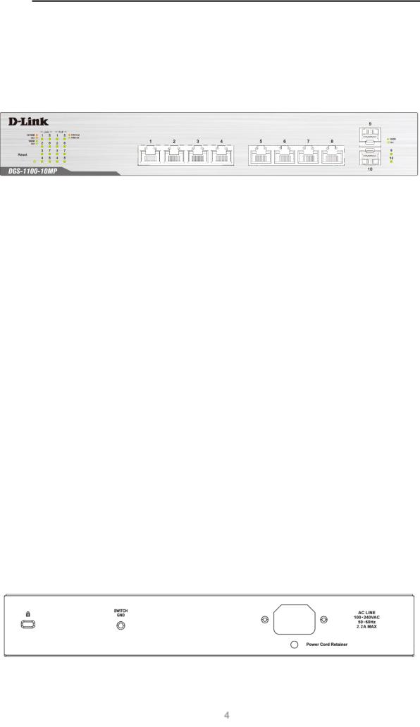
DGS-1100-10MP
8-Port 10/100/1000 Mbps + 2-Port SFP 1000 Mbps PoE switch
Front Panel
Figure 2-1 - DGS-1100-10MP Front Panel
Power LED: The Power LED lights up when the switch is connected to a power source.
Link/Act/Speed LED (Ports 1-8):
Solid Green: When there is a secure 1000Mbps connection at the port.
Blinking Green or Amber: Indicates that the switch is either sending or receiving data to the port.
Solid Amber: Indicates that the port is running at 10/100Mbps. Light off: No link.
PoE Mode (Ports 1- 8):
Green: Indicates that PoE mode is active.
Amber: Indicates that there is an issue with the PoE mode activating properly. Light off: Indicates that PoE mode is not active.
Link/Act/Speed LED (Ports 9-10):
Solid Green: There is a secure 1000Mbps connection at the port. Blinking Green: There is reception or transmission occurring at the port. Light off: No link.
Reset: By pressing the Reset button until the power LED turns amber, the switch will change back to the default configuration and all changes will be lost.
Rear Panel
Figure 2-2 – DGS-1100-10MP Rear Panel
4

D-Link DGS-1100 MP/MPP Series Switch User Manual
Power: The power port is where to connect the AC power cord.
CAUTION: The SFP ports should use UL listed Optical Transceiver product, Rated Laser Class I. 3.3Vdc.
CAUTION: This equipment is to be connected only to PoE networks without routing to the outside plant.
5
D-Link DGS-1100 MP/MPP Series Switch User Manual
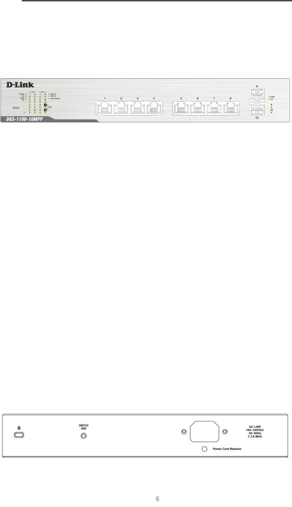
DGS-1100-10MPP
8-Port 10/100/1000 Mbps + 2-Port SFP 1000 Mbps PoE switch
Front Panel
Figure 2-3 – DGS-1100-10MPP Front Panel
Power LED: The Power LED lights up when the switch is connected to a power source.
Link/Act/Speed LED (Ports 1-8):
Solid Green: When there is a secure 1000Mbps connection at the port.
Blinking Green or Amber: Indicates that the switch is either sending or receiving data to the port.
Solid Amber: Indicates that the port is running at 10/100Mbps. Light off: No link.
PoE Mode (Ports 1- 8):
Green: Indicates that PoE mode is active.
Amber: Indicates that there is an issue with the PoE mode activating properly. Light off: Indicates that PoE mode is not active.
Link/Act/Speed LED (Ports 9-10):
Solid Green: There is a secure 1000Mbps connection at the port. Blinking Green: There is reception or transmission occurring at the port. Light off: No link.
Reset: By pressing the Reset button until the power LED turns amber, the switch will change back to the default configuration and all changes will be lost.
Rear Panel
Figure 2-4 – DGS-1100-10MPP Rear Panel
6
D-Link DGS-1100 MP/MPP Series Switch User Manual
Power: Connect the supplied AC power cable to this port.
CAUTION: The SFP ports should use UL listed Optical Transceiver product, Rated Laser Class I. 3.3Vdc.
CAUTION: This equipment is to be connected only to PoE networks without routing to the outside plant.
7
D-Link DGS-1100 MP/MPP Series Switch User Manual
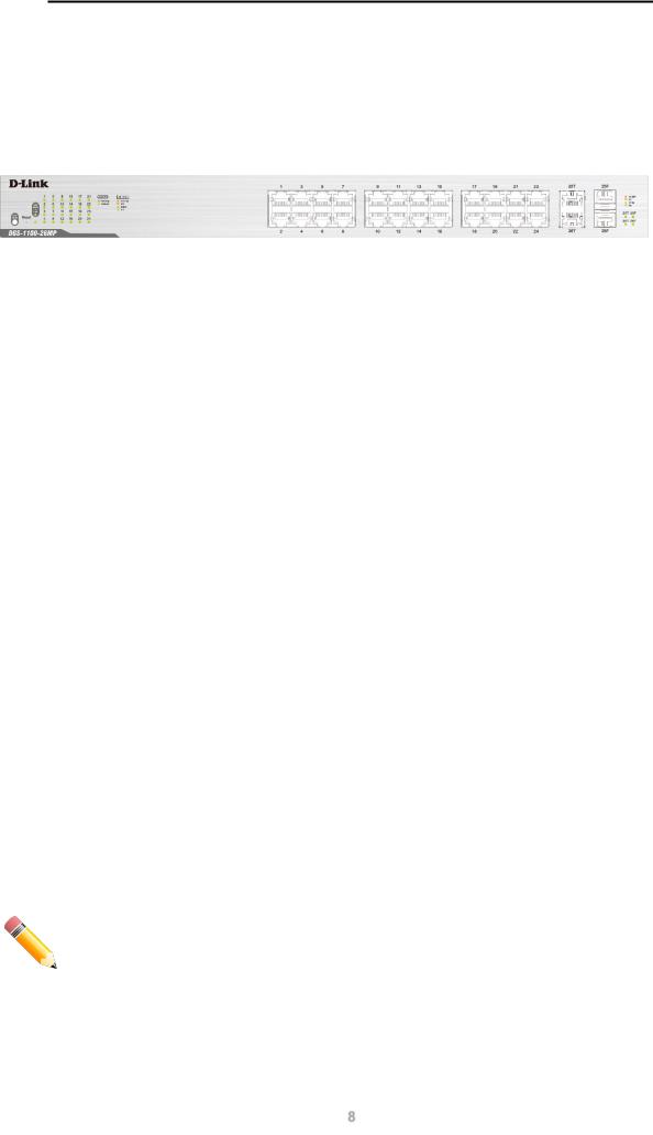
DGS-1100-26MP
24-Port 10/100/1000 Mbps + 2-Port Combo 1000BASE-T/SFP PoE switch
Front Panel
Figure 2-5 – DGS-1100-26MP Front Panel
Power LED: The Power LED lights up when the switch is connected to a power source.
Link/Act/Speed LED (Ports 1-24):
Solid Green: When there is a secure 1000Mbps connection at the port.
Blinking Green or Amber: Indicates that the switch is either sending or receiving data to the port.
Solid Amber: Indicates that the port is running at 10/100Mbps. Light off: No link.
PoE Mode (Ports 1- 24):
Green: Indicates that PoE mode is active.
Amber: Indicates that there is an issue with the PoE mode activating properly. Light off: Indicates that PoE mode is not active.
Link/Act/Speed LED (Ports 25-26):
Solid Green: There is a secure 1000Mbps connection at the port. Blinking Green: There is reception or transmission occurring at the port. Solid Amber: Indicates that the port is running at 10/100Mbps.
Light off: No link.
LED Mode Button: Pressing this button will change the LED behavior from Link mode, and PoE Mode.
Reset: By pressing the Reset button until the power LED turns amber, the switch will change back to the default configuration and all changes will be lost.
NOTE: The LED behavior for ports 1- 24 will switch between Link mode and PoE mode when the PoE mode is active.
8

D-Link DGS-1100 MP/MPP Series Switch User Manual
Rear Panel
Figure 2-6 – DGS-1100-26MP Rear Panel
Power: Connect the supplied AC power cable to this port.
CAUTION: The SFP ports should use UL listed Optical Transceiver product, Rated Laser Class I. 3.3Vdc.
CAUTION: This equipment is to be connected only to PoE networks without routing to the outside plant.
9
D-Link DGS-1100 MP/MPP Series Switch User Manual
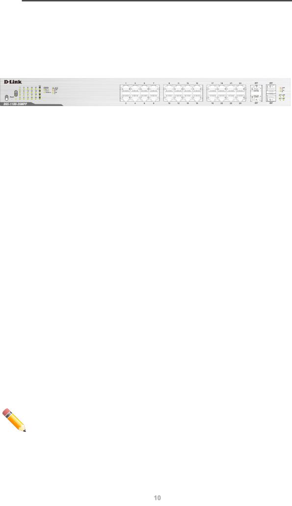
DGS-1100-26MPP
24-Port 10/100/1000 Mbps + 2-Port Combo 1000BASE-T/SFP PoE switch
Front Panel
Figure 2-7 – DGS-1100-26MPP Front Panel
Power LED: The Power LED lights up when the switch is connected to a power source.
Link/Act/Speed LED (Ports 1-24):
Solid Green: When there is a secure 1000Mbps connection at the port.
Blinking Green or Amber: Indicates that the switch is either sending or receiving data to the port.
Solid Amber: Indicates that the port is running at 10/100Mbps. Light off: No link.
PoE Mode (Ports 1- 24):
Green: Indicates that PoE mode is active.
Amber: Indicates that there is an issue with the PoE mode activating properly. Light off: Indicates that PoE mode is not active.
Link/Act/Speed LED (Ports 25-26):
Solid Green: There is a secure 1000Mbps connection at the port. Blinking Green: There is reception or transmission occurring at the port. Solid Amber: Indicates that the port is running at 10/100Mbps.
Light off: No link.
LED Mode Button: Pressing this button will change the LED behavior from Link mode, and PoE Mode.
Reset: By pressing the Reset button until the power LED turns amber, the switch will change back to the default configuration and all changes will be lost.
NOTE: The LED behavior for ports 1- 24 will switch between Link mode and PoE mode when the PoE mode is active.
10
D-Link DGS-1100 MP/MPP Series Switch User Manual
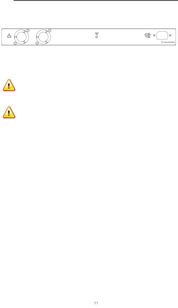
Rear Panel
Figure 2-8 – DGS-1100-26MPP Rear Panel
Power: Connect the supplied AC power cable to this port.
CAUTION: The SFP ports should use UL listed Optical Transceiver product, Rated Laser Class I. 3.3Vdc.
CAUTION: This equipment is to be connected only to PoE networks without routing to the outside plant.
11

D-Link DGS-1100 MP/MPP Series Switch User Manual
3.Hardware Installation
This chapter provides unpacking and installation information for the D-Link switch.
Step 1: Unpacking
Open the shipping carton and carefully unpack its contents. Please consult the packing list located below to make sure all items are present and undamaged. If any item is missing or damaged, please contact your local D-Link reseller for a replacement.
Packing Contents
•One D-Link DGS-1100 MP/MPP Series switch
•One AC power cord
•Four rubber feet
•Screws and two mounting brackets
•One accessory kit for a ground screw
•One Multi-lingual Getting Started Guide
•One CD with User Manual
Step 2: Switch Installation
For safe switch installation and operation, it is recommended that you:
•Visually inspect the power cord to see that it is secured fully to the AC power connector.
•Make sure that there is proper heat dissipation and adequate ventilation around the switch.
•Do not place heavy objects on the switch.
Desktop or Shelf Installation
When installing the switch on a desktop or shelf, the rubber feet included with the device must be attached on the bottom at each corner of the device’s base. Allow enough ventilation space between the device and the objects around it.
Figure 3-1 – Attach the adhesive rubber pads to the bottom
Rack Installation
The switch can be mounted in an EIA standard size 19-inch rack, which can be placed in a wiring closet with other equipment.
12
D-Link DGS-1100 MP/MPP Series Switch User Manual
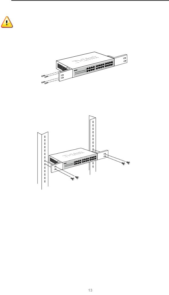
CAUTION: Ensure the power cable is disconnected before installing the switch.
To install, attach the mounting brackets to the switch’s side panels (one on each side) and secure them with the screws provided.
Figure 3-2 – Attach the mounting brackets to the switch
Then, use the screws provided with the equipment rack to mount the switch in the rack.
Figure 3-3 – Mount the switch in the rack or chassis
Please be aware of following safety Instructions when installing:
A)Elevated Operating Ambient - If installed in a closed or multi-unit rack assembly, the operating ambient temperature of the rack environment may be greater than room ambient. Therefore, consideration should be given to installing the equipment in an environment compatible with the maximum ambient temperature (Tma) specified by the manufacturer.
B)Reduced Air Flow - Installation of the equipment in a rack should be such that the amount of air flow required for safe operation of the equipment is not compromised.
C)Mechanical Loading - Mounting of the equipment in the rack should be such that a hazardous condition is not achieved due to uneven mechanical loading.
D)Circuit Overloading - Consideration should be given to the connection of the equipment to the supply circuit and the effect that overloading of the circuits might have on overcurrent protection and supply wiring. Appropriate consideration of equipment nameplate ratings should be used when addressing this concern.
13

D-Link DGS-1100 MP/MPP Series Switch User Manual
E) Reliable Earthing - Reliable earthing of rack-mounted equipment should be maintained. Particular attention should be given to supply connections other than direct connections to the branch circuit (e.g. use of power strips)."
Step 3: Plugging in the AC Power Cord
Users may now connect the AC power cord into the rear of the switch and to an electrical outlet (preferably one that is grounded and surge protected).
Figure 3-4 – Plugging the switch into an outlet
Power Failure
As a precaution, the switch should be unplugged in case of power failure. When power is resumed, the switch should be plugged back in.
Grounding the Switch
This section describes how to connect the DGS-1100 MP/MPP Series switch to ground. You must complete this procedure before powering your switch.
Required Tools and Equipment
•Ground screws (included in the accessory kit): One M4 x 6 mm (metric) pan-head screw
•Ground cable (not included in the accessory kit): The grounding cable should be sized according to local and national installation requirements. Depending on the power supply and system, a 12 to 6 AWG copper conductor is required for U.S installation. Commercially available 6 AWG wire is recommended. The length of the cable depends on the proximity of the switch to proper grounding facilities.
•A screwdriver (not included in the accessory kit)
Follow these steps to ground the switch:
Step 1: Verify that the switch is not connected to a power supply.
Step 2: Use the ground cable to place the #8 terminal lug ring on top of the ground-screw opening, as seen in the figure below.
Step 3: Insert the ground screw into the ground-screw opening.
Step 4: Using a screwdriver, tighten the ground screw to secure the ground cable to the switch.
14

D-Link DGS-1100 MP/MPP Series Switch User Manual
Step 5: Attach the terminal lug ring at the other end of the grounding cable to an appropriate grounding stud or bolt on rack where the switch is installed.
Step 6: Verify if the connections at the ground connector on the switch and the rack are securely attached.
Figure 3-5 – Ground cable, screw and #8 terminal lug rings
CAUTION: This equipment is to be connected only to PoE networks without routing to the outside plant.
15
Loading...