


 Loading...
D-Link ™ DES-3250TG
Stackable Layer 2 Switch
User’s Guide
____________________

D-Link DES-3250TG Standalone Layer 2 Switch
Information in this document is subject to change without notice. © 2005 D-Link Computer Corporation. All rights reserved.
Reproduction in any manner whatsoever without the written permission of D-Link Computer Corporation is strictly forbidden.
Trademarks used in this text: D-Link and the D-Link logo are trademarks of D-Link Computer Corporation; Microsoft and Windows are registered trademarks of Microsoft Corporation.
Other trademarks and trade names may be used in this document to refer to either the entities claiming the marks and names or their products. D-Link Computer Corporation disclaims any proprietary interest in trademarks and trade names other than its own.
March 2005 P/N 651TG3250055
ii

D-Link DES-3250TG Standalone Layer 2 Switch |
|
|
Table of Contents |
Preface .............................................................................................................................................. |
vii |
Intended Readers............................................................................................................................... |
vii |
Notes, Notices, and Cautions .......................................................................................................... |
vii |
Safety Instructions......................................................................................................................... |
viii |
Protecting Against Electrostatic Discharge ....................................................................................... |
x |
Introduction.......................................................................................................................................... |
1 |
Fast Ethernet Technology ................................................................................................................... |
1 |
Gigabit Ethernet Technology............................................................................................................... |
1 |
Switch Stacking.................................................................................................................................. |
1 |
Features ............................................................................................................................................. |
2 |
Ports................................................................................................................................................... |
2 |
Traffic Classification and Prioritization ............................................................................................... |
3 |
Management....................................................................................................................................... |
3 |
Unpacking and Setup............................................................................................................................ |
4 |
Unpacking .......................................................................................................................................... |
4 |
Installation ......................................................................................................................................... |
4 |
Desktop or Shelf Installation ............................................................................................................ |
4 |
Rack Installation.............................................................................................................................. |
5 |
Power on............................................................................................................................................. |
6 |
Power Failure ................................................................................................................................... |
6 |
Identifying External Components .......................................................................................................... |
7 |
Front Panel......................................................................................................................................... |
7 |
Rear Panel .......................................................................................................................................... |
7 |
Side Panels......................................................................................................................................... |
8 |
Gigabit Combo Ports........................................................................................................................... |
8 |
LED Indicators ................................................................................................................................... |
8 |
Connecting the Switch ........................................................................................................................ |
10 |
Switch to End Node .......................................................................................................................... |
10 |
Switch to Hub or Switch ................................................................................................................... |
10 |
10BASE-T Device ........................................................................................................................... |
11 |
100BASE-TX Device....................................................................................................................... |
11 |
Stacking vs. Standalone Operation ................................................................................................... |
11 |
Managing Switch Stacks................................................................................................................... |
12 |
Changes to Switch Stack Structure ................................................................................................ |
13 |
Convert a Standalone Switch to a Stacked Switch.......................................................................... |
13 |
Add a Switch to a Stack ................................................................................................................. |
14 |
Swap a Master from a Stack........................................................................................................... |
15 |
Stacking with DGS-3312SR ........................................................................................................... |
16 |
Introduction to Switch Management.................................................................................................... |
17 |
Management Options........................................................................................................................ |
17 |
Web-based Management Interface .................................................................................................... |
17 |
SNMP-Based Management................................................................................................................ |
17 |
Command Line Console Interface Through the Serial Port ................................................................ |
17 |
Connecting the Console Port (RS-232 DCE).................................................................................... |
18 |
First Time Connecting to The Switch ................................................................................................ |
19 |
Password Protection ......................................................................................................................... |
20 |
SNMP Settings.................................................................................................................................. |
21 |
Traps ............................................................................................................................................. |
22 |
iii |
|

D-Link DES-3250TG Standalone Layer 2 Switch |
|
MIBs .............................................................................................................................................. |
22 |
IP Address Assignment ..................................................................................................................... |
22 |
Connecting Devices to the Switch ..................................................................................................... |
24 |
Web-based Switch Management.......................................................................................................... |
25 |
Introduction ..................................................................................................................................... |
25 |
Login to Web Manager ...................................................................................................................... |
25 |
User Accounts Management ............................................................................................................. |
26 |
Admin and User Privileges.............................................................................................................. |
26 |
Save Changes ................................................................................................................................... |
27 |
Areas of the User Interface................................................................................................................ |
28 |
Web Pages ........................................................................................................................................ |
29 |
Configuration ...................................................................................................................................... |
30 |
IP Address ........................................................................................................................................ |
31 |
Switch Information ........................................................................................................................... |
33 |
Advanced Settings ............................................................................................................................ |
33 |
Serial Port Settings ........................................................................................................................... |
35 |
MAC Notification............................................................................................................................... |
35 |
Port Configuration ............................................................................................................................ |
36 |
Port Description................................................................................................................................ |
38 |
Port Mirroring................................................................................................................................... |
39 |
Stack Setting .................................................................................................................................... |
41 |
Static ARP Settings........................................................................................................................... |
42 |
IGMP ................................................................................................................................................ |
43 |
IGMP Snooping .............................................................................................................................. |
43 |
Static Router Ports Entry ............................................................................................................... |
45 |
Spanning Tree .................................................................................................................................. |
46 |
STP Switch Settings ....................................................................................................................... |
48 |
STP Port Settings ........................................................................................................................... |
50 |
Forwarding Filtering ......................................................................................................................... |
53 |
Unicast Forwarding........................................................................................................................ |
53 |
Multicast Forwarding ..................................................................................................................... |
53 |
VLANs .............................................................................................................................................. |
55 |
Static VLAN Entry .......................................................................................................................... |
57 |
Port VLAN ID(PVID)........................................................................................................................ |
60 |
Port Bandwidth ................................................................................................................................ |
63 |
SNTP Settings................................................................................................................................... |
65 |
Current Time Settings .................................................................................................................... |
65 |
Time Zone and DST........................................................................................................................ |
66 |
Port Security..................................................................................................................................... |
66 |
Port Security Settings..................................................................................................................... |
67 |
Port Security Clear......................................................................................................................... |
68 |
QOS (Quality of Service).................................................................................................................... |
70 |
Traffic Control................................................................................................................................ |
70 |
802.1p Default Priority................................................................................................................... |
72 |
802.1p User Priority....................................................................................................................... |
74 |
(QOS Output) Scheduling............................................................................................................... |
74 |
Traffic Segmentation ...................................................................................................................... |
75 |
LACP ................................................................................................................................................ |
76 |
Link Aggregation ............................................................................................................................ |
76 |
LACP Port ...................................................................................................................................... |
79 |
Configuring the Access Profile Table ................................................................................................. |
80 |
System Log Hosts ............................................................................................................................. |
97 |
Port Access Entity (802.1X)............................................................................................................... |
97 |
802.1x Port-Based and MAC-Based Access Control........................................................................ |
97 |
Authentication Server .................................................................................................................... |
98 |
iv |
|

D-Link DES-3250TG Standalone Layer 2 Switch |
|
Authenticator................................................................................................................................. |
99 |
Client ........................................................................................................................................... |
100 |
Authentication Process................................................................................................................. |
101 |
Understanding 802.1x Port-based and MAC-based Network Access Control................................. |
101 |
Port-Based Network Access Control ............................................................................................. |
102 |
MAC-Based Network Access Control ............................................................................................ |
103 |
Configure Authenticator............................................................................................................... |
103 |
Port Capability Settings................................................................................................................ |
106 |
Initialize Port(s) for Port Based 802.1x.......................................................................................... |
108 |
Initializing Ports for MAC Based 802.1x ....................................................................................... |
109 |
Reauthenticate Port(s) for Port Based 802.1x ............................................................................... |
109 |
Reauthenticate Port(s) for MAC-based 802.1x .............................................................................. |
110 |
RADIUS Server............................................................................................................................. |
110 |
Management ..................................................................................................................................... |
112 |
Security IP...................................................................................................................................... |
112 |
User Accounts ................................................................................................................................ |
112 |
SNMPV3 ......................................................................................................................................... |
113 |
SNMP User Table ......................................................................................................................... |
113 |
SNMP View Table ......................................................................................................................... |
115 |
SNMP Group Table....................................................................................................................... |
117 |
SNMP Community Table .............................................................................................................. |
119 |
SNMP Host Table ......................................................................................................................... |
120 |
SNMP Engine ID .......................................................................................................................... |
121 |
Monitoring ........................................................................................................................................ |
122 |
CPU Utilization ............................................................................................................................... |
122 |
Port Utilization................................................................................................................................ |
123 |
Packets........................................................................................................................................... |
125 |
Received (RX) ............................................................................................................................... |
125 |
UMB-cast (RX) ............................................................................................................................. |
127 |
Transmitted (TX) .......................................................................................................................... |
129 |
Errors............................................................................................................................................. |
131 |
Received (RX) ............................................................................................................................... |
131 |
Transmitted (TX) .......................................................................................................................... |
133 |
Size ................................................................................................................................................ |
135 |
Packet Size................................................................................................................................... |
135 |
MAC Address.................................................................................................................................. |
137 |
ARP Table ....................................................................................................................................... |
139 |
IGMP Snooping Group .................................................................................................................... |
140 |
IGMP Snooping Forwarding ............................................................................................................ |
141 |
VLAN Status ................................................................................................................................... |
142 |
Router Port..................................................................................................................................... |
143 |
Port Access Control ........................................................................................................................ |
143 |
Authenticator Status.................................................................................................................... |
143 |
Maintenance ..................................................................................................................................... |
145 |
TFTP Utilities.................................................................................................................................. |
145 |
Download Firmware from Server .................................................................................................. |
145 |
Download Settings from TFTP Server............................................................................................ |
146 |
Upload Settings to TFTP Server .................................................................................................... |
146 |
Upload Log to TFTP Server ........................................................................................................... |
146 |
Switch History ................................................................................................................................ |
147 |
Ping Test......................................................................................................................................... |
147 |
Save Changes ................................................................................................................................. |
148 |
Reboot Services .............................................................................................................................. |
148 |
Reboot ......................................................................................................................................... |
149 |
v |
|

D-Link DES-3250TG Standalone Layer 2 Switch |
|
Reset............................................................................................................................................ |
149 |
Reset System ............................................................................................................................... |
149 |
Reset Config................................................................................................................................. |
150 |
Logout.......................................................................................................................................... |
150 |
Appendix A ....................................................................................................................................... |
150 |
Technical Specifications.................................................................................................................. |
150 |
Appendix B ....................................................................................................................................... |
153 |
Understanding and Troubleshooting the Spanning Tree Protocol .................................................... |
153 |
Warranty and Registration ................................................................................................................ |
162 |
vi

D-Link DES-3250TG Standalone Layer 2 Switch
Preface
The DES-3250TG Manual is divided into sections that describe the system installation and operating instructions with examples.
Section 1, Introduction - Describes the Switch and its features.
Section 2, Unpacking and Setup- Helps you get started with the basic installation of the Switch and also describes the front panel, rear panel, side panels, and LED indicators of the Switch.
Section 3, Identifying External Components - Tells how you can connect the Switch to your Ethernet network.
Section 4, Connecting The Switch - This chapter describes how to connect the DES-3250TG to your Ethernet/Fast Ethernet/Gigabit Ethernet network.
Section 5, Switch Management and Operating Concepts - This chapter discusses many of the concepts and features used to manage the switch, as well as the concepts necessary for the user to understand the functioning of the switch.
Section 6, Web-Based Switch Management - Introduces basic Switch management features, including password protection, SNMP settings, IP address assignment and connecting devices to the Switch.
Section 7, Configuration - A detailed discussion about configuring some of the basic functions of the Switch, including accessing the Switch information, using the Switch's utilities and setting up network configurations, such as Quality of Service, The Access Profile Table, port mirroring and configuring the Spanning Tree.
Section 8, Management – A detailed discussion regarding the Simple Network Monitoring Protocol including description of features and a brief introduction to SNMP.
Section 9, Monitoring - Features graphs and screens used in monitoring features and packets on the Switch.
Section 10, Maintenance - Features information on Switch utility functions, including TFTP Services, Switch History, Ping Test, Save Changes and Rebooting Services.
Appendix A, Technical Specifications - The technical specifications of the Switch.
Appendix B, Understanding and Troubleshooting Spanning Tree Protocol -
Intended Readers
The DES-3250 User’s Guide contains information for setup and management and of the DES-3250TG switch. This guide is intended for network managers familiar with network management concepts and terminology.
Notes, Notices, and Cautions
NOTE: A NOTE indicates important information that helps you make better use of your device.
vii
D-Link DES-3250TG Standalone Layer 2 Switch
NOTICE: A NOTICE indicates either potential damage to hardware or loss of data and tells you how to avoid the problem.
CAUTION: A CAUTION indicates a potential for property damage, personal injury, or death.
Safety Instructions
Use the following safety guidelines to ensure your own personal safety and to help protect your system from potential damage. Throughout this safety section, the caution icon  ) is used to indicate cautions and precautions that you need to review and follow.
Safety Cautions
To reduce the risk of bodily injury, electrical shock, fire, and damage to the equipment, observe the following precautions.
Observe and follow service markings. Do not service any product except as explained in your system documentation. Opening or removing covers that are marked with the triangular symbol with a lightning bolt may expose you to electrical shock. Only a trained service technician should service components inside these compartments.
If any of the following conditions occur, unplug the product from the electrical outlet and replace the part or contact your trained service provider:
–The power cable, extension cable, or plug is damaged.
–An object has fallen into the product.
–The product has been exposed to water.
–The product has been dropped or damaged.
–The product does not operate correctly when you follow the operating instructions.
•Keep your system away from radiators and heat sources. Also, do not block cooling vents.
•Do not spill food or liquids on your system components, and never operate the product in a wet environment. If the system gets wet, see the appropriate section in your troubleshooting guide or contact your trained service provider.
•Do not push any objects into the openings of your system. Doing so can cause fire or electric shock by shorting out interior components.
•Use the product only with approved equipment.
•Allow the product to cool before removing covers or touching internal components.
•Operate the product only from the type of external power source indicated on the electrical ratings label. If you are not sure of the type of power source required, consult your service provider or local power company.
•To help avoid damaging your system, be sure the voltage selection switch (if provided) on the power supply is set to match the power available at your location:
–115 volts (V)/60 hertz (Hz) in most of North and South America and some Far Eastern countries such as South Korea and Taiwan
–100 V/50 Hz in eastern Japan and 100 V/60 Hz in western Japan
–230 V/50 Hz in most of Europe, the Middle East, and the Far East
•Also be sure that attached devices are electrically rated to operate with the power available in your location.
•Use only approved power cable(s). If you have not been provided with a power cable for your system or for any ACpowered option intended for your system, purchase a power cable that is approved for use in your country. The power cable must be rated for the product and for the voltage and current marked on the product's electrical ratings label.
The voltage and current rating of the cable should be greater than the ratings marked on the product.
viii
D-Link DES-3250TG Standalone Layer 2 Switch
Safety Instructions (continued)
•To help prevent electric shock, plug the system and peripheral power cables into properly grounded electrical outlets. These cables are equipped with three-prong plugs to help ensure proper grounding. Do not use adapter plugs or remove the grounding prong from a cable. If you must use an extension cable, use a 3-wire cable with properly grounded plugs.
•Observe extension cable and power strip ratings. Make sure that the total ampere rating of all products plugged into the extension cable or power strip does not exceed 80 percent of the ampere ratings limit for the extension cable or power strip.
•To help protect your system from sudden, transient increases and decreases in electrical power, use a surge suppressor, line conditioner, or uninterruptible power supply (UPS).
•Position system cables and power cables carefully; route cables so that they cannot be stepped on or tripped over. Be sure that nothing rests on any cables.
•Do not modify power cables or plugs. Consult a licensed electrician or your power company for site modifications. Always follow your local/national wiring rules.
•When connecting or disconnecting power to hot-pluggable power supplies, if offered with your system, observe the following guidelines:
–Install the power supply before connecting the power cable to the power supply.
–Unplug the power cable before removing the power supply.
–If the system has multiple sources of power, disconnect power from the system by
unplugging all power cables from the power supplies.
•Move products with care; ensure that all casters and/or stabilizers are firmly connected to the system. Avoid sudden stops and uneven surfaces.
General Precautions for Rack-Mountable Products
Observe the following precautions for rack stability and safety. Also refer to the rack installation documentation accompanying the system and the rack for specific caution statements and procedures.
Systems are considered to be components in a rack. Thus, "component" refers to any system as well as to various peripherals or supporting hardware.
CAUTION: Installing systems in a rack without the front and side stabilizers installed could cause the rack to tip over, potentially resulting in bodily injury under certain circumstances. Therefore, always install the stabilizers before installing components in the rack.
After installing system/components in a rack, never pull more than one component out of the rack on its slide assemblies at one time. The weight of more than one extended component could cause the rack to tip over and may result in serious injury.
•Before working on the rack, make sure that the stabilizers are secured to the rack, extended to the floor, and that the full weight of the rack rests on the floor. Install front and side stabilizers on a single rack or front stabilizers for joined multiple racks before working on the rack.
ix
D-Link DES-3250TG Standalone Layer 2 Switch
Safety Instructions (continued)
Always load the rack from the bottom up, and load the heaviest item in the rack first. Make sure that the rack is level and stable before extending a component from the rack.
Use caution when pressing the component rail release latches and sliding a component into or out of a rack; the slide rails can pinch your fingers.
After a component is inserted into the rack, carefully extend the rail into a locking position, and then slide the component into the rack.
Do not overload the AC supply branch circuit that provides power to the rack. The total rack load should not exceed 80 percent of the branch circuit rating.
Ensure that proper airflow is provided to components in the rack.
Do not step on or stand on any component when servicing other components in a rack.
NOTE: A qualified electrician must perform all connections to DC power and to safety grounds. All electrical wiring must comply with applicable local or national codes and practices.
CAUTION: Never defeat the ground conductor or operate the equipment in the absence of a suitably installed ground conductor. Contact the appropriate electrical inspection authority or an electrician if you are uncertain that suitable grounding is available.
CAUTION: The system chassis must be positively grounded to the rack cabinet frame. Do not attempt to connect power to the system until grounding cables are connected. Completed power and safety ground wiring must be inspected by a qualified electrical inspector. An energy hazard will exist if the safety ground cable is omitted or disconnected.
Protecting Against Electrostatic Discharge
Static electricity can harm delicate components inside your system. To prevent static damage, discharge static electricity from your body before you touch any of the electronic components, such as the microprocessor. You can do so by periodically touching an unpainted metal surface on the chassis.
You can also take the following steps to prevent damage from electrostatic discharge (ESD):
1.When unpacking a static-sensitive component from its shipping carton, do not remove the component from the antistatic packing material until you are ready to install the component in your system. Just before unwrapping the antistatic packaging, be sure to discharge static electricity from your body.
2.When transporting a sensitive component, first place it in an antistatic container or packaging.
3.Handle all sensitive components in a static-safe area. If possible, use antistatic floor pads and workbench pads and an antistatic grounding strap.
x
D-Link DES-3250TG Standalone Layer 2 Switch
Section 1
Introduction
Fast Ethernet Technology
Gigabit Ethernet Technology
Switch Stacking
Performance Features
Ports
This section describes the functionality features of the DES-3250TG.
Fast Ethernet Technology
100Mbps Fast Ethernet (or 100BASE-T) is a standard specified by the IEEE 802.3 LAN committee. It is an extension of the 10Mbps Ethernet standard with the ability to transmit and receive data at 100Mbps, while maintaining the Carrier Sense Multiple Access with Collision Detection (CSMA/CD) Ethernet protocol.
Gigabit Ethernet Technology
Gigabit Ethernet is an extension of IEEE 802.3 Ethernet utilizing the same packet structure, format, and support for full duplex and management objects, but with a tenfold increase in theoretical throughput over 100Mbps Fast Ethernet and a one hundredfold increase over 10Mbps Ethernet. Since it is compatible with all 10Mbps and 100Mbps Ethernet environments, Gigabit Ethernet provides a straightforward upgrade without wasting a company’s existing investment in hardware, software, and trained personnel.
Switch Stacking
The DES-3250TG can be used as a standalone or a stacked Switch by using the optional stacking module. Up to 12 Switches may be stacked and managed as a unit with a single IP address. Management for the entire stack is done through the Master Switch. You may add Switches later as needed. The Switch can also be grouped in a stack as a slave with the DES-3312SL Switch (acting as the Master).
1

D-Link DES-3250TG Standalone Layer 2 Switch
Features
The DES-3250TG Switch was designed for easy installation and high performance in an environment where traffic on the network and the number of users increase continuously.
Switch features include:
•Store and forward switching scheme.
•Full and half-duplex for both 10Mbps and 100Mbps connections. The front-port Gigabit Ethernet module operates at full duplex only. Full duplex allows the switch port to simultaneously transmit and receive data, and only works with connections to full-duplex capable end stations and switches. Connections to hubs must take place at half-duplex.
•Auto-polarity detection and correction of incorrect polarity on the transmit and receive twisted-pair at each port.
•IEEE 802.3z compliant for Mini GBIC ports (optional module).
•IEEE 802.3ab compliant for 1000BASE-T (Copper) Gigabit ports (optional module).
•Data forwarding rate 14,880 pps per port at 100% of wire-speed for 10Mbps speed.
•Data forwarding rate 148,800 pps per port at 100% of wire-speed for 100Mbps speed.
•Data filtering rate eliminates all error packets, runts, etc. at 14,880 pps per port at 100% of wire-speed for 10Mbps speed.
•Data filtering rate eliminates all error packets, runts, etc. at 148,800 pps per port at 100% of wire-speed for 100Mbps speed.
•8K active MAC address entry table per device with automatic learning and aging (10 to 1,000,000 seconds).
•64 MB packet buffer per device.
•Supports Port Mirroring.
•Supports Port Trunking.
•802.1D Spanning Tree support.
•802.1Q Tagged VLAN support – up to 255 VLANs per device (one VLAN is reserved for internal use).
•GVRP – (GARP VLAN Registration Protocol) support for dynamic VLAN registration.
•802.1p Priority support with 4 priority queues.
•IGMP Snooping support.
Ports
•Forty-eight high-performance NWay ports all operating at 10/100 Mbps for connecting to end stations, servers and hubs.
•All 48 10/100 UTP ports can auto-negotiate (NWay) between 10Mbps/100Mbps, half-duplex or full duplex.
•One front panel slide-in module interface for a 2-port 1000BASE-T module (provided) and one front panel slide-in module interface for a 2-port Mini GBIC Gigabit Ethernet module (optional). Please note that although these two front
2

D-Link DES-3250TG Standalone Layer 2 Switch
panel modules can be used simultaneously, the ports must be different. For example, if port 49x is used on the Mini GBIC module, port 49x is not available on the 1000BASE-T module, and vice versa.
•RS-232 DCE Diagnostic port (console port) for setting up and managing the Switch via a connection to a console terminal or PC using a terminal emulation program.
Traffic Classification and Prioritization
•Based on 802.1p priority bits.
•Four priority queues.
Management
•RS-232 console port for out-of-band network management via a console terminal or PC.
•Fast Spanning Tree Algorithm Protocol for creation of alternative backup paths and prevention of network loops.
•SNMP V1, V2C, and V3 are supported.
•Fully configurable in-band control for SNMP based software.
•Flash memory for software upgrades. This can be done in-band via TFTP or out-of-band via the console.
•Built-in SNMP management:
SNMP V2-MIB (RFC 1907).
Bridge MIB (RFC 1493).
MIB-II (RFC 1213).
IF MIB (RFC 2233).
Entity MIB (RFC 2737).
RMON MIB (RFC 1757) – 4 groups. The RMON specification defines the Counters for the Receive function only. However, the DES-3250TG implements counters for both receive and transmit functions.
802.1p MIB (RFC 2674).
Ether-Like MIB (RFC 2358) – dot3StatsTable.
•Supports Web-based management.
•CLI management support.
•TFTP support.
•BOOTP support.
•DHCP Client support.
•Password enabled.
3

D-Link DES-3250TG Standalone Layer 2 Switch
Section 2
Unpacking and Setup
Unpacking
Installation
Power On
This chapter provides unpacking and setup information for the Switch.
Unpacking
Open the shipping carton of the Switch and carefully unpack its contents. The carton should contain the following items:
•One DES-3250TG Standalone Layer 2 Switch
•Mounting kit: 2 mounting brackets and screws
•Four rubber feet with adhesive backing
•One AC power cord
•This User’s Guide with Registration Card
If any item is found missing or damaged, please contact your local D-Link reseller for replacement.
Installation
Use the following guidelines when choosing a place to install the Switch:
•The surface must support at least 5 kg
•The power outlet should be within 1.82 meters (6 feet) of the device
•Visually inspect the power cord and see that it is secured to the AC power connector
•Make sure that there is proper heat dissipation from and adequate ventilation around the switch. Do not place heavy objects on the switch
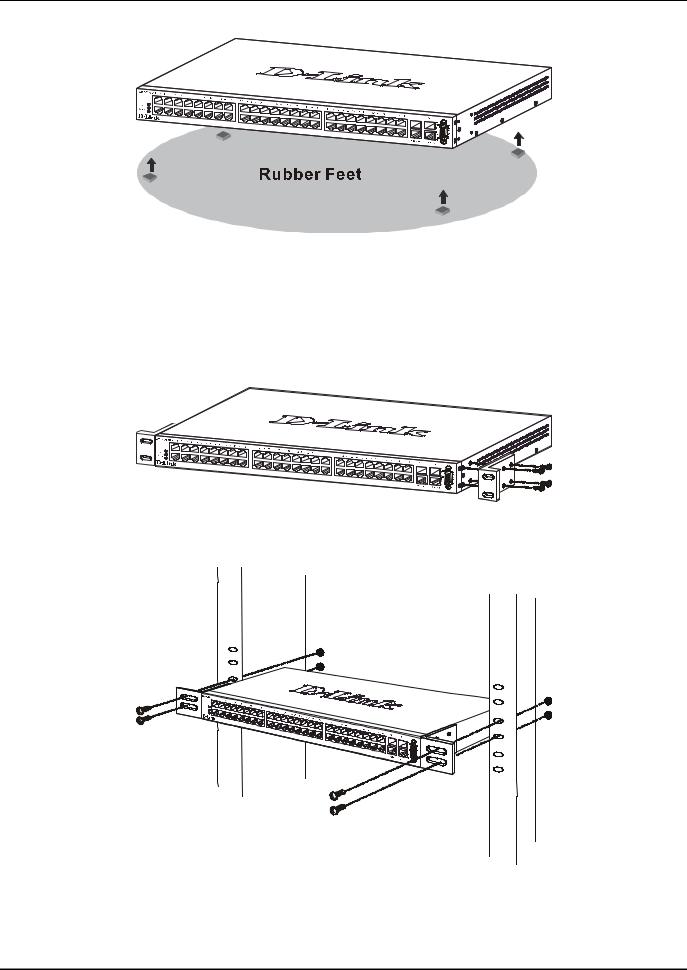
Desktop or Shelf Installation
When installing the Switch on a desktop or shelf, the rubber feet included with the device should first be attached. Attach these cushioning feet on the bottom at each corner of the device. Allow adequate space for ventilation between the device and the objects around it.
4
D-Link DES-3250TG Standalone Layer 2 Switch
Figure 2-1. Installing rubber feet for desktop installation
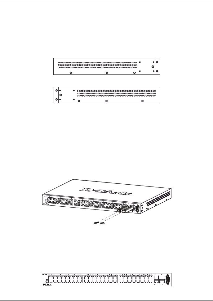
Rack Installation
The DES-3250TG can be mounted in an EIA standard-sized, 19-inch rack, which can be placed in a wiring closet with other equipment. To install, attach the mounting brackets on the switch’s side panels (one on each side) and secure them with the screws provided.
Figure 2- 2. Attaching the mounting brackets to the switch
Then, use the screws provided with the equipment rack to mount the switch on the rack.
Figure 2-3. Installing the switch on an equipment rack
5

D-Link DES-3250TG Standalone Layer 2 Switch
Power on
The DES-3250TG switch can be used with AC power supply 100 - 240 VAC, 50 - 60 Hz. The power switch is located at the rear of the unit adjacent to the AC power connector and the system fan. The switch’s power supply will adjust to the local power source automatically and may be turned on without having any or all LAN segment cables connected.
After the power switch is turned on, the LED indicators should respond as follows:
•All LED indicators will momentarily blink. This blinking of the LED indicators represents a reset of the system
•The power LED indicator is always on after the power is turned ON
•The console LED indicator will blink while the Switch loads onboard software and performs a self-test. It will remain ON if there is a connection at the RS-232 port, otherwise this LED indicator is OFF
Power Failure
As a precaution in the event of a power failure, unplug the switch. When the power supply is restored, plug the switch back in.
6
D-Link DES-3250TG Standalone Layer 2 Switch
Section 3
Identifying External Components
Front Panel
Rear Panel
Side Panels
Gigabit Combo Ports
LED Indicators
This chapter describes the front panel, rear panel, side panels, and optional plug-in module, and LED indicators of the DES-3250TG.
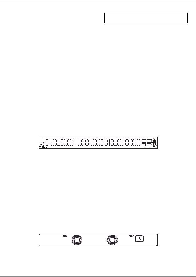
Front Panel
The front panel of the Switch consists of LED indicators, an RS-232 communication port, 48 (10/100 Mbps) Ethernet/Fast Ethernet ports, and a pair of Gigabit Ethernet Combo ports for 1000BASE-T (plug-in module provided) and Mini GBIC connections (optional plug-in module).
Figure 3-1. Front panel view of the Switch
●Comprehensive LED indicators display the status of the switch and the network (see the LED Indicators section below).
●An RS-232 DCE console port for setting up and managing the switch via a connection to a console terminal or PC using a terminal emulation program.
●Forty-eight high-performance NWay Ethernet ports, all of which operate at 10/100 Mbps for connections to end stations, servers and hubs. All ports can auto-negotiate between 10Mbps or 100Mbps and full or half duplex.
●Two Gigabit Ethernet Combo ports for making 1000BASE-T and Mini GBIC connections.
Rear Panel
The rear panel of the switch consists of two fans and an AC power connector.
Figure 3-2. Rear panel view of the Switch
The system fans are used to dissipate heat. The sides of the system also provide heat vents to serve the same purpose. Do not block these openings, and leave at least 6 inches of space at the rear and sides of the switch for proper ventilation. Be reminded that without proper heat dissipation and air circulation, system components might overheat, which could lead to system failure.
7
D-Link DES-3250TG Standalone Layer 2 Switch
The AC power connector is a standard three-pronged connector that supports the power cord. Plug-in the female connector of the provided power cord into this socket, and the male side of the cord into a power outlet. Supported input voltages range from 100 ~ 240 VAC at 50 ~ 60 Hz.
Side Panels
Each side panel contains heat vents to help to dissipate heat.
Figure 3-3. Side panel views of the Switch
The system fans are used to dissipate heat. The sides of the system also provide heat vents to serve the same purpose. Do not block these openings, and leave at least 6 inches of space at the rear and sides of the switch for proper ventilation. Be reminded that without proper heat dissipation and air circulation, system components might overheat, which could lead to system failure.
Gigabit Combo Ports
In addition to the 48 10/100 Mbps ports, the Switch features two Gigabit Ethernet Combo ports. These two ports are 1000BASE-T copper ports (provided) and Mini-GBIC ports (optional). See the diagram below to view the two Mini-GBIC port modules being plugged into the Switch. Please note that although these two front panel modules can be used simultaneously, the ports must be different. The GBIC port will always have the highest priority.
Figure 3-4. Mini-GBIC modules plug-in to the Switch
LED Indicators
The LED indicators of the Switch include Power, Console, and Link/Act. The following shows the LED indicators for the Switch along with an explanation of each indicator.
Figure 3-5. The LED Indicators
8

D-Link DES-3250TG Standalone Layer 2 Switch
●Power – This indicator on the front panel should be lit during the Power-On Self Test (POST). It will light green approximately 2 seconds after the switch is powered on to indicate the ready state of the device.
●Console – This indicator is lit green when the switch is being managed via local console management through the RS-232 console port.
●Link/Act – These indicators are located to the left and right of each port. They are lit when there is a secure connection (or link) to a device at any of the ports. The LEDs blink whenever there is reception or transmission (i.e. Activity--Act) of data occurring at a port.
9
D-Link DES-3250TG Standalone Layer 2 Switch
Section 4
Connecting the Switch
Switch to End Node Switch to Hub or Switch 10BASE-T Device 100BASE-TX Device
Stacking vs. Standalone Operation
Managing Switch Stacks
This chapter describes how to connect the DES-3250TG to your Ethernet/Fast Ethernet/Gigabit Ethernet network. The Switch’s auto-detection feature allows all 48 10/100 ports to support both MDI-II and MDI-X connections.
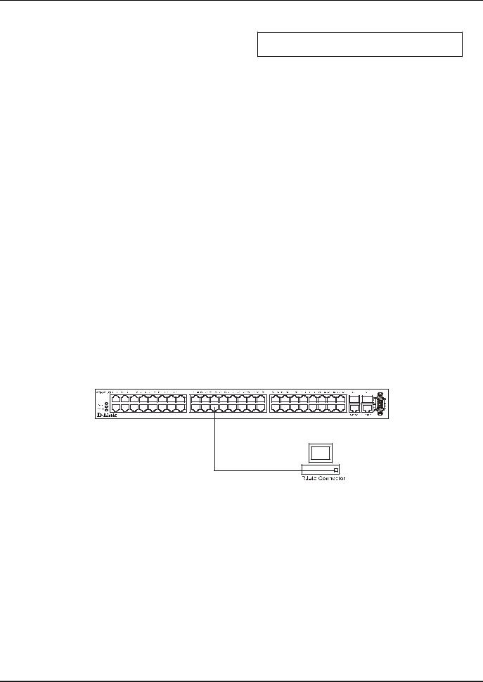
Switch to End Node
End nodes include PCs outfitted with a 10, 100, or 10/100 Mbps RJ-45 Ethernet/Fast Ethernet Network Interface Card (NIC) and most routers.
An end node can be connected to the Switch via a two-pair Category 3, 4, or 5 UTP/STP cable. The end node should be connected to any of the ports (1x - 48x) on the switch.
Figure 4- 1. Switch connected to an End Node
The Link/Act LEDs in the top row for each UTP port light green when the link is valid. A blinking LED in the top row indicates packet activity on that port.
Switch to Hub or Switch
These connections can be accomplished in a number of ways using a normal cable.
●A 10BASE-T hub or switch can be connected to the Switch via a two-pair Category 3, 4 or 5 UTP/STP cable.
●A 100BASE-TX hub or switch can be connected to the Switch via a two-pair Category 5 UTP/STP cable.
10
D-Link DES-3250TG Standalone Layer 2 Switch
Figure 4- 2. Switch connected to a port on a hub or switch using a straight or crossover cable
10BASE-T Device
For a 10BASE-T device, the Switch’s LED indicators should display the following:
● Link/Act indicator is ON.
100BASE-TX Device
For a 100BASE-TX device, the Switch’s LED indicators should display the following:
● Link/Act is ON.
Stacking vs. Standalone Operation
By default, the Switch configuration settings allow it to operate as a standalone device, or in a stacked group. It is not necessary to change any settings for the Switch to function in either capacity. However, it is useful to understand how the stacking mode operates in the Switch and the effects if any this may have on configuration settings in a Switch when its stacking status is changed.
Stacking mode is enabled by default and can be changed using the CLI command config stacking mode. If the Switch has stacking mode enabled and is properly connected to other DES-3250TG Switches, a negotiation takes place upon starting up the Switches to determine how the Switch functions in the stack. For an all-DES-3250TG stack, any time a change occurs in the structure or composition of a stacked Switch group the entire stack will restart and the negotiation process begins anew. When the stacking mode is disabled (config stacking mode disable), the Switch only allows standalone operation. If stacking mode is disabled on a Switch, it should be disconnected from a stacked group.
NOTE: The firmware for Release 4 allows stacking operation of the DES-3250TG as a slave to the DGS-3312SR in a star topology. See the example below for more information.
Stacking mode can be changed using the CLI. When a DES-3250TG Switch stack is first assembled, it is advisable to determine which Switch will function as the master before placing the Switches in a rack and connecting them. If the Switch is used in a stacked group with the DGS-3312SR, the DGS-3312SR operates as the master and the DES-3250TG Switches in the stacked group operate as slaves. The possible stacking configuration modes are as follows:
Enabled: Stacking mode is enabled by default. When enabled the Switch can operate as a standalone device or it can operate with other DES-3250TG Switches in a properly connected stacked group. Stacking must be enabled for the Switch to function in a stacked arrangement with other DES-3250TG Switches or with a DGS-3312SR Switch.
Auto: This is the default stacking mode setting for the DES-3250TG. In auto stacking mode, the Switch is eligible for stacking or it can operate as a standalone device. If a DES-3250TG Switch stack is connected and all units are configured to operate in
11

D-Link DES-3250TG Standalone Layer 2 Switch
auto stacking mode, the master-slave relationships is determined automatically. For DES-3250TG Switch stacks, the unit with the lowest MAC address becomes the master (stack number 1). The order in which slave devices appear logically in the stack (stack number 2+) is determined by how they are connected relative to the master Switch. The auto mode serves to first determine if the device is stacked or standalone, then if stacked, it determines which Switch is the master and the remaining stack numbers for the slave Switches.
Master: The auto mode described above may be overridden so that a properly connected Switch in a stack may be forced into master mode. Only one Switch in a stack may act as the master and all configuration settings for the stacked group - including stacking configuration - are saved in configuration files in the master Switch. The stack is managed as a single entity through the master. It may be convenient to place the master unit in the upper-most slot of a stacked group to visually distinguish it form the slave units. The master unit should be used to uplink the stack group to the backbone. If the master unit fails or is replaced for any reason, it is possible to load configuration files saved from the original master unit in order to continue operation with identical settings. See the example below for a description of how to swap the master unit of a stacked group. A Switch configured as the stack master will maintain this status regardless of any changes that occur in the composition of the stacked group. If for example a connection to a slave unit or a connection between two slave units were to fail, the entire stack will restart automatically. After restarting, the designated master unit retains its status.
Slave: The auto mode may be overridden to force the Switch to operate in slave mode. When the Switch is in slave mode, it is ineligible to function as a master and all configuration, is done through the master unit. A master Switch must be properly connected to the stack for a Switch to operate in slave mode.
Disabled: This forces the Switch to operate as a standalone device. In standalone mode the Switch functions as a standalone device even if a stacking module is installed. To force standalone operation it is necessary to use the CLI command config stacking mode disable. A Switch that has stacking mode disabled should never connect to another Switch through stacking ports.
NOTICE: Do not use stacking ports on a Switch that has the stacking mode disabled.
For DES-3250TG Switch stacks, changes made to the composition of a Switch stack group, that is, adding new Switches or taking Switches out of the stack, require all Switches to restart. The new stacking order is negotiated to reflect the changes made to the group. If the master Switch has been configured to force master status it retains this status, likewise Switches forced to operate in slave mode retain the status after restarting. The restart occurs automatically if any stacking link is disconnected.
For star topology arrangements, the DGS-3312SR Switches do not restart when a link or Switch failure occurs. Only the effected Switch will restart if its link to the DGS-3312SR Switch fails. The remaining DES-3250TG Switches continue to operate as before.
The command show stacking can be used to view stacking information. If stacking has been disabled, the stacking mode will be listed as Standalone.
Managing Switch Stacks
Multiple DES-3250TG Switches equipped with stacking modules may be connected in a stacking arrangement so that up to twelve Switches are managed as a single unit with a single IP address. The Release 4 DES-3250TG can connect to the DGS3312SR via the stacking port in a star topology. Up to twelve Switches may be connected to the DGS-3312SR and be managed as slave devices through the DGS-3312SR Switch.
The default stacking mode will establish a master Switch for the stack through a negotiation process that takes place when all devices are started up. In a DES-3250TG stack, the Switches negotiate the master-slave relationship. Once the master Switch is determined, the remaining Switches function as slaves. The stack number of the slave Switches is determined by where it is actually positioned in the stack. This can be taken into account when you are placing the Switches in an equipment rack.
For star topology stacking arrangements with the DGS-3312SR, the default settings of the DES-3250TG assign slave status and the unit number is determined by the number of the port connected at the other end of the stacking connection.
12
D-Link DES-3250TG Standalone Layer 2 Switch
Keep in mind the following important considerations for stacked Switch groups:
•All management of the Switches in the stack is done through the master Switch.
•The master Switch should be used to uplink to the Ethernet backbone.
For DES-3250TG stacks, the master Switch can be chosen automatically as each Switch in a connected stack competes for status. However, you can choose a specific device and force it to operate as the master. Use the CLI command config stacking mode enabled master for the selected Switch; leave the remaining Switches in the default autostacking mode.
For DES-3250TG stacks, if the link between any two Switches fails or is disconnected, or if any Switch in a stacked group fails, all of the Switches in the stack will automatically reboot. Since the stack is connected as a ring, the stack will need to be connected to work around the failed link. Change the cabling to bypass the failed link and allow the stack to reboot. The Switches will negotiate again since the composition of the stack has been altered. Read below for more information about changes in stacked Switch groups.
A Switch stack has a single IP address − if the stacking link to a given Switch fails or is disconnected, that Switch will loose its status in the stack and reboot as a standalone device with the IP settings it had before becoming a member of the Switch stack.
NOTE: For Release 4 the DES-3250TG maintains two separate configurations, one for standalone operation and another for stacked operation. Each configuration has identical IP settings, VLANs, link aggregation, QoS, etc. This dual system allows a Switch to change status from standalone to stacking enabled and keep its configuration settings.
Changes to Switch Stack Structure
If Switches are added to or taken out of a stacked group of DES-3250TG Switches it is necessary to change the composition of a Switch stack and rearrange the stacking connections. If a stacking link fails or if a member of a stacked group fails, the composition of the stack will necessarily change also. In such a case intervention is required to at least reconnect the stacking cable to bypass the failure. In addition to making changes to the cable links connecting the Switches in the stack, it may be necessary or desirable to change the stacking mode configuration of one or more units. A few examples presented below to help make the changes to cable connections for DES-3250TG stacks and if necessary, to Switch stacking mode configuration settings.
NOTE: For a Switch that has already been configured with many settings already in place, it is a good idea to save the configuration files to a server before changing the stacking mode status. Configuration files can be saved using the CLI, SNMP manager or web manager interface.
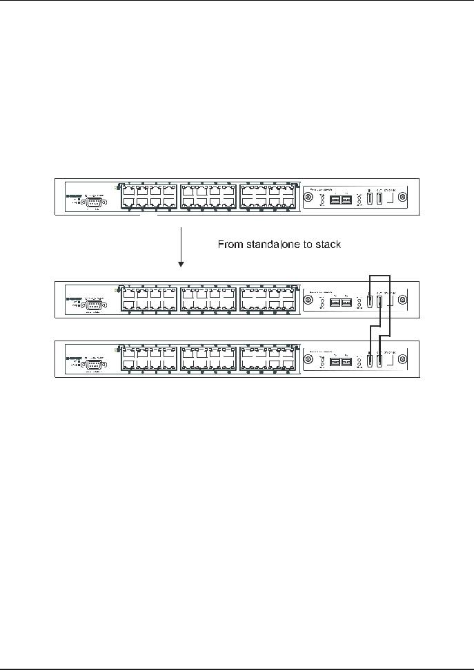
Convert a Standalone Switch to a Stacked Switch
A Switch that has previously acted in a standalone capacity may become a member of a stacked group simply by installing a stacking module and connecting it to a connected Switch stack. For this example, let’s assume Switch A has been setup as a standalone device and has been functioning on the network. We want to join this Switch with another DES-3250TG, Switch B, to form a 2-Switch stack. Many configuration settings including IP settings have already been set on Switch A so we will keep these and use them for the new stacked arrangement. Switch A is also uplinked to the backbone via the GBIC port in the stacking module. Switch A will stay in its position in the uppermost slot in the rack and all network connections will remain in place.
First, save the configuration files to a TFTP server so they may be reloaded if any problems occur. This should be done whether or not stacking mode is changed.
13
D-Link DES-3250TG Standalone Layer 2 Switch
Since we want to keep the same IP address and all the other settings on the standalone Switch, this Switch will become the master of the stack and Switch B will become the slave. To make sure Switch A functions as the master we will enable stacking and override the auto function.
Use the CLI to enter the command: config stacking mode enable master
The stacking mode for Switch B is set to the default auto-stacking mode and therefore no changes are required. Switch B will lose configuration settings including its IP settings, so if you want to save these be sure to upload the configuration files before making the stacking connection.
Power off both devices and place Switch B under Switch A in the rack. It is not actually required that the slave device be placed under the master in the stack but it may be easier so that the master Switch may be instantly recognized. This may prove especially convenient where multiple Switch stacks are installed so it is always clear which unit should be used to uplink.
Figure 4- 3. Convert a Standalone Switch to a Stacked Switch
Both Switches are now powered off. Switch B is placed securely in the rack and connected to Switch A via the stacking ports. Both devices are powered on; they recognize the stacking connection and begin negotiating the stacking relationship. Switch A is configured to function as the master device. Switch B automatically assume slave status. Switch A will keep its IP settings and its other configurations remain unchanged. The stack may now be configured as a single entity.
Add a Switch to a Stack
Adding a new slave device to a Switch stack is a simple procedure. If you are swapping an existing Switch, label each Ethernet cable attached to the device being swapped so they can be placed in the same port number in the replacement device.
To add a new slave to a stack, place the new unit in the next available slot below the stack. Power off all Switches in the stack and make the necessary changes to the stacking cable connections. Use the illustrations below as a guide.
14

D-Link DES-3250TG Standalone Layer 2 Switch
Figure 4- 4. Add a Switch to a Stack
Switch C is added to the existing stack where Switch A is the designated master. Power off all devices and securely place Switch C in the slot beneath Switch B. Adjust stacking cable connections so the OUT port on Switch B connects the IN port on Switch C and the OUT port of Switch C connects to the IN port of Switch A.
Figure 4- 5. Add a third Switch to a stack
Power on the entire stack. The new stacking arrangement is recognized and the new relationship is negotiated. Switch A retains status as the master of the stack, Switch C is in auto mode and therefore functions as a slave. The stack is ready for operation.
Swap a Master from a Stack
Let’s assume the stack arrangement in the previous example has a problem that requires the master unit, Switch A, to be replaced. In this case, we can preserve all the same configuration settings by downloading the previously saved configuration files to the replacement Switch.
Before disconnecting the network connections of the original master unit, label each Ethernet cable so they can be placed in the same port number in the replacement Switch. Then remove the device from the rack.
Place the replacement Switch in the same slot. Power on the new Switch and attach a console cable to it. Configure the new unit to be a master and save the settings. Connect the Ethernet cable needed to access the TFTP server containing the saved configuration files of the previous master unit. Download the saved configuration files, use the command:
download configuration <ipaddr> <path_filename>
Save the new settings and power off the Switch. Now the stacking connections and Ethernet connections can be completed exactly as before. Reconnect the stacking cables and Ethernet connections and power on the entire stack. The stack should now function as before with all the configuration settings intact.
15
D-Link DES-3250TG Standalone Layer 2 Switch
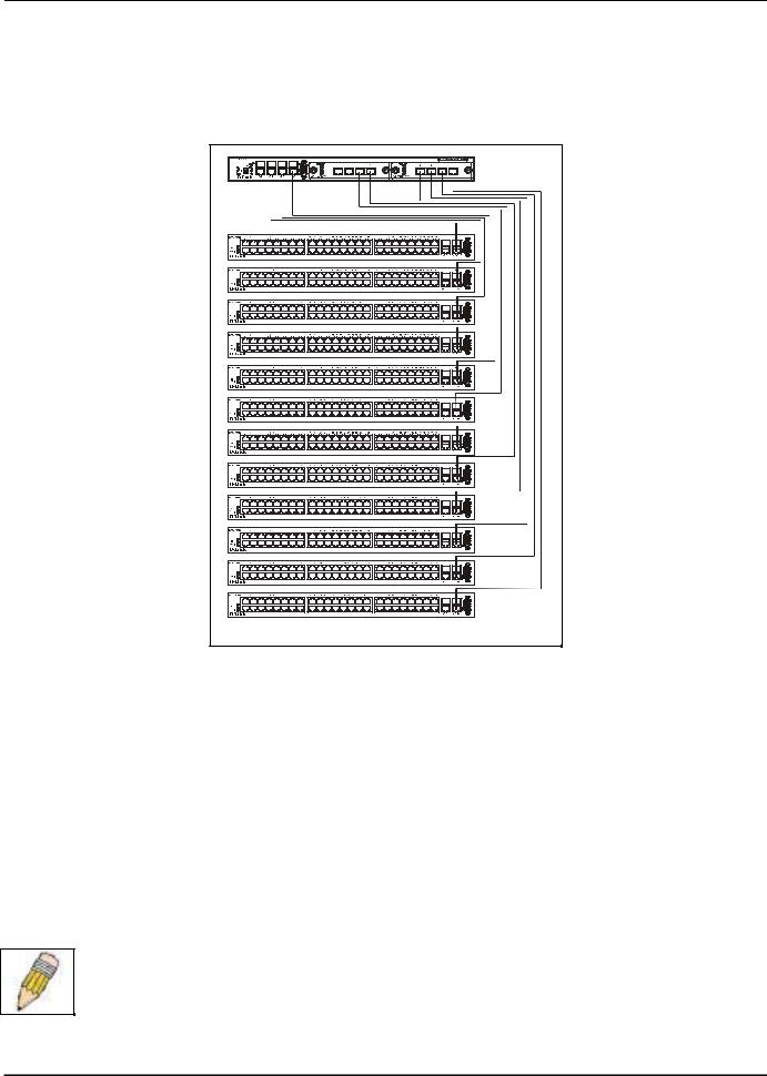
Stacking with DGS-3312SR
The DES-3250TG Release 4 Switch can be arranged in a star topology and managed as slave devices through the DGS3312SR Master Switch. Up to twelve Switches can be connected to the DGS-3312SR Switch in this arrangement.
Figure 4- 6. DES-3250TG Switches with DGS-3312SR |
Setting up a star topology with a DGS-3312SR is a simple matter. Each DES-3250TG connects to the master through the stacking port to a similar stacking port on a DGS-3312SR Switch equipped with one or two special stacking modules designed for the DES-3250TG Switch. Each DES-3250TG slave must be configured with stacking mode enabled. When stacked in a star topology arrangement with the DGS-3312SR, the Switch will automatically assume slave status. The unit number is determined by the port number to which it is connected on the DGS-3312SR master. The DGS-3312SR must have a stacking module installed and have stacking mode enabled as well. Stacking for the DGS-3312SR uses the identical CLI command: config stacking mode enable. Be sure to save the configuration change using the CLI command save.
Remember that for star topology arrangements, if the stacking link to a given Switch fails or is disconnected, that Switch will lose its status in the stack and reboot as a standalone device with the IP settings. The DGS-3312SR and remaining slave units are not effected by the link failure.
NOTE: The DES-3250TG must have stacking mode enabled to be used with the DGS-3312SR in a star topology arrangement.
16

D-Link DES-3250TG Standalone Layer 2 Switch
Section 5
Introduction to Switch Management
Management Options
Web-based Management Interface
SNMP-Based Management
Managing User Accounts
Command Line Console Interface through the Serial Port
Connecting the Console Port (RS-232 DCE)
First Time Connecting to the Switch
Password Protection
SNMP Settings
IP Address Assignment
Connecting Devices to the Switch
Management Options
This system may be managed out-of-band through the console port on the front panel or in-band using Telnet. The user may also choose the web-based management, accessible through a web browser.
Web-based Management Interface
After you have successfully installed the Switch, you can configure the Switch, monitor the LED panel, and display statistics graphically using a web browser, such as Netscape Navigator (version 6.2 and higher) or Microsoft® Internet Explorer (version 5.0).
SNMP-Based Management
You can manage the Switch with an SNMP-compatible console program. The Switch supports SNMP version 1.0, version 2.0 and version 3.0. The SNMP agent decodes the incoming SNMP messages and responds to requests with MIB objects stored in the database. The SNMP agent updates the MIB objects to generate statistics and counters.
Command Line Console Interface Through the Serial Port
You can also connect a computer or terminal to the serial console port to access the Switch. The command-line-driven interface provides complete access to all Switch management features.
17

D-Link DES-3250TG Standalone Layer 2 Switch
Connecting the Console Port (RS-232 DCE)
The Switch provides an RS-232 serial port that enables a connection to a computer or terminal for monitoring and configuring the Switch. This port is a female DB-9 connector, implemented as a data terminal equipment (DTE) connection.
To use the console port, you need the following equipment:
•A terminal or a computer with both a serial port and the ability to emulate a terminal.
•A null modem or crossover RS-232 cable with a female DB-9 connector for the console port on the Switch.
To connect a terminal to the console port:
1.Connect the female connector of the RS-232 cable directly to the console port on the Switch, and tighten the captive retaining screws.
2.Connect the other end of the cable to a terminal or to the serial connector of a computer running terminal emulation software. Set the terminal emulation software as follows:
3.Select the appropriate serial port (COM port 1 or COM port 2).
4.Set the data rate to 9600 baud.
5.Set the data format to 8 data bits, 1 stop bit, and no parity.
6.Set flow control to none.
7.Under Properties, select VT100 for Emulation mode.
8.Select Terminal keys for Function, Arrow, and Ctrl keys. Ensure that you select Terminal keys (not Windows keys).
NOTE: When you use HyperTerminal with the Microsoft® Windows® 2000 operating system, ensure that you have Windows 2000 Service Pack 2 or later installed. Windows 2000 Service Pack 2 allows you to use arrow keys in HyperTerminal's VT100 emulation. See www.microsoft.com for information on Windows 2000 service packs.
9.After you have correctly set up the terminal, plug the power cable into the power receptacle on the back of the Switch. The boot sequence appears in the terminal.
10.After the boot sequence completes, the console login screen displays.
11.Usernames and Passwords are not required on the initial screen after the first connection. Any additional user names and passwords must first be created by the administrator. If you have previously set up user accounts, log in and continue to configure the Switch.
12.Enter the commands to complete your desired tasks. Many commands require administrator-level access privileges. Read the next section for more information on setting up user accounts. See the DES-3250TG Command Line Interface Reference Manual on the documentation CD for a list of all commands and additional information on using the CLI.
13.When you have completed your tasks, exit the session with the logout command or close the emulator program.
Make sure the terminal or PC you are using to make this connection is configured to match these settings.
If you are having problems making this connection on a PC, make sure the emulation is set to VT-100. You will be able to set the emulation by clicking on the File menu in you HyperTerminal window, clicking on Properties in the drop-down menu, and then clicking the Settings tab. This is where you will find the Emulation options. If you still do not see anything, try rebooting the Switch by disconnecting its power supply.
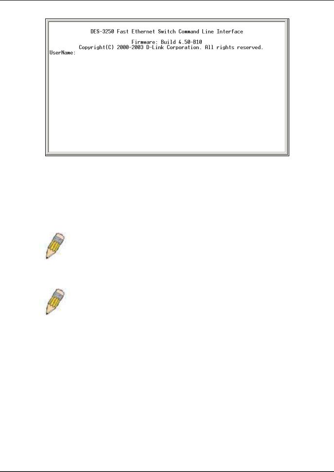
Once connected to the console, the screen below will appear on your console screen. This is where the user will enter commands to perform all the available management functions. The Switch will prompt the user to enter a user name and a password. Upon the initial connection, the user name and password are not required. These can be changed or deleted later.
18
D-Link DES-3250TG Standalone Layer 2 Switch
Figure 5- 1. Initial screen after first connection
First Time Connecting to The Switch
The Switch supports user-based security that can allow you to prevent unauthorized users from accessing the Switch or changing its settings. This section tells how to log onto the Switch.
NOTE: The passwords used to access the Switch are case-sensitive; therefore, "S" is not the same as "s."
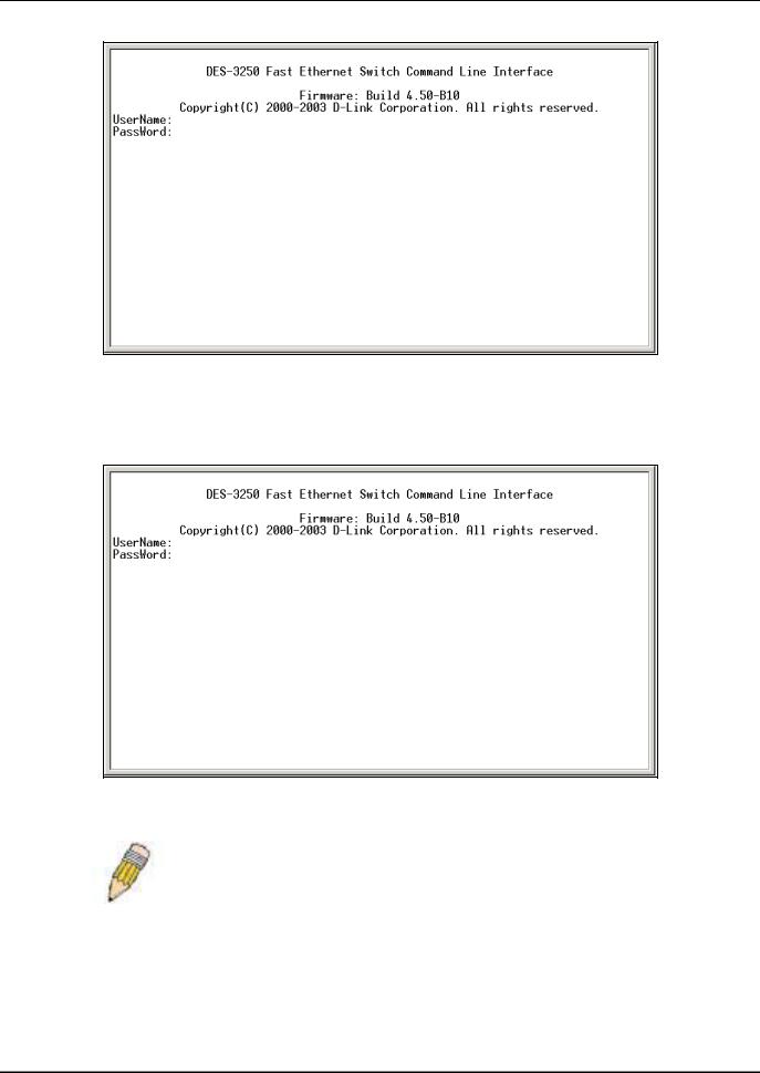
When you first connect to the Switch, you will be presented with the first login screen (shown below).
NOTE: Press Ctrl+R to refresh the screen. This command can be used at any time to force the console program in the Switch to refresh the console screen.
19
D-Link DES-3250TG Standalone Layer 2 Switch
Figure 5- 2. Initial screen, first time connecting to the Switch
Usernames and Passwords are not required on the initial screen after the first connection. Any additional user names and passwords must first be created by the administrator. You will be given access to the command prompt DES-3250TG:4# shown below:
Figure 5- 3. Command Prompt
NOTE: The first user automatically gets Administrator level privileges. It is recommended to create at least one Admin-level user account for the Switch.
Password Protection
The DES-3250TG does not have a default user name and password. One of the first tasks when settings up the Switch is to create user accounts. If you log in using a predefined administrator-level user name, you have privileged access to the Switch's management software.
20
Loading...