


DGS-3100-24
Documentation also available on
CD and D-Link Website
Getting Started Guide
For D-Link Managed
Switches
2
ENGLISH
About This Guide
This guide gives step-by-step instructions for setting up all
D-Link managed switches and relative Warranty, Safety,
Regulatory, and Environment Notice. Please note that the
model you have purchased may appear slightly different
from those shown in the illustrations.
For more detailed information about your switch, its
components, making network connections, and technical
specications, please refer to the User’s Guide included
with your switch.
Step 1 – Unpacking
Open the shipping carton and carefully unpack its
contents. Please consult the packing list located in the
User Guide to make sure all items are present and
undamaged. If any item is missing or damaged, please
contact your local D-Link reseller for replacement.
Items Included in Switch Packages
Item
Type of Switch
Unmanaged
Smart or
Managed
Palm
Desktop/Rack
Mount
Chassis
Device Yes Yes Yes Yes
Console Cable No No Ye s Ye s
Rack
Mounting
Brackets
No Yes Yes Yes
Rubber Feet Yes Yes Yes Yes
Power Cord
(Adapter)
Yes Yes Yes Yes
Multi-lingual
Getting Started
Guide
Yes Yes Yes Yes
Power cord retainer No No Ye s No
CD No No Ye s Ye s
Step 2 – Switch Installation
For safe switch installation and operation, it is
recommended that you:
• Visually inspect the power cord to see that it is secured
fully to the AC power connector.
• Make sure that there is proper heat dissipation and
adequate ventilation around the switch.
• Do not place heavy objects on the switch
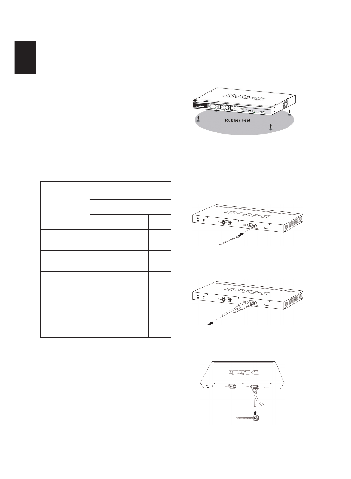
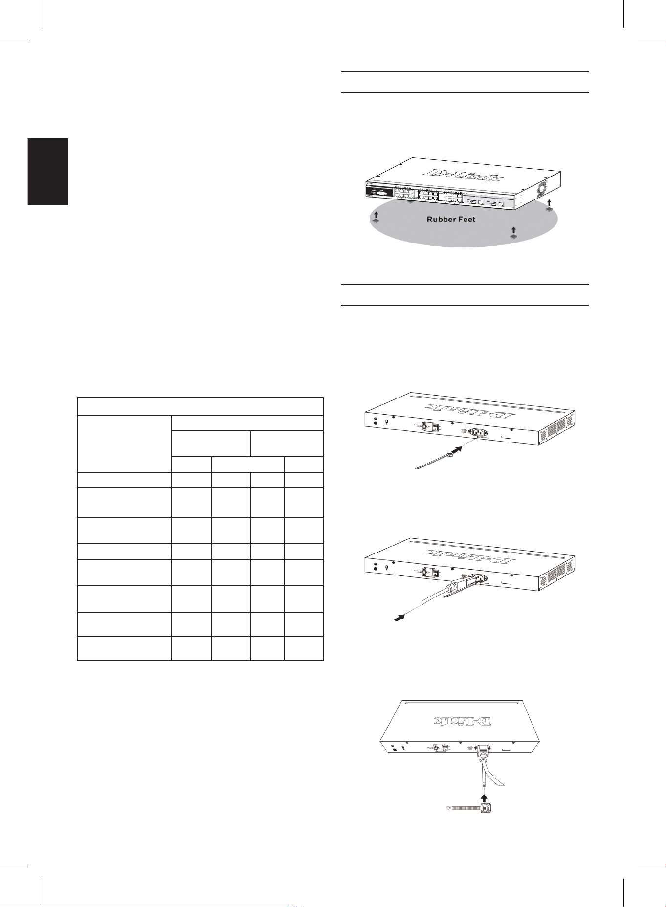
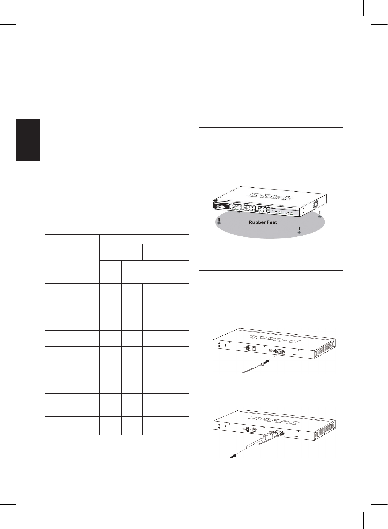
Desktop or Shelf Installation
When installing the switch on a desktop or shelf, the
rubber feet included with the device must be attached
on the bottom at each corner of the device’s base. Allow
enough ventilation space between the device and the
objects around it.
Figure 1. Attaching the rubber feet
Installing Power Cord Retainer
To prevent accidental removal of the AC power cord, it is
recommended to install the power cord retainer together
with the power cord.
1. With the rough side facing down, insert the Tie Wrap
into the hole below the power socket.
Figure 2-1. Insert Tie Wrap to the Switch
2. Plug the AC power cord into the power socket of the
Switch.
Figure 2-2. Connect the power cord to the Switch
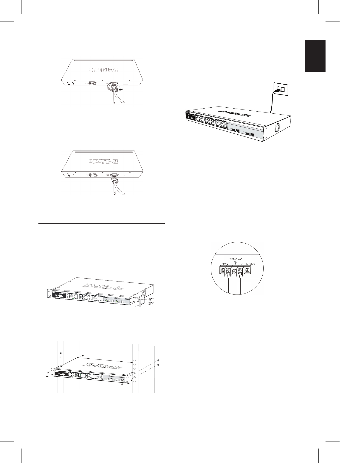
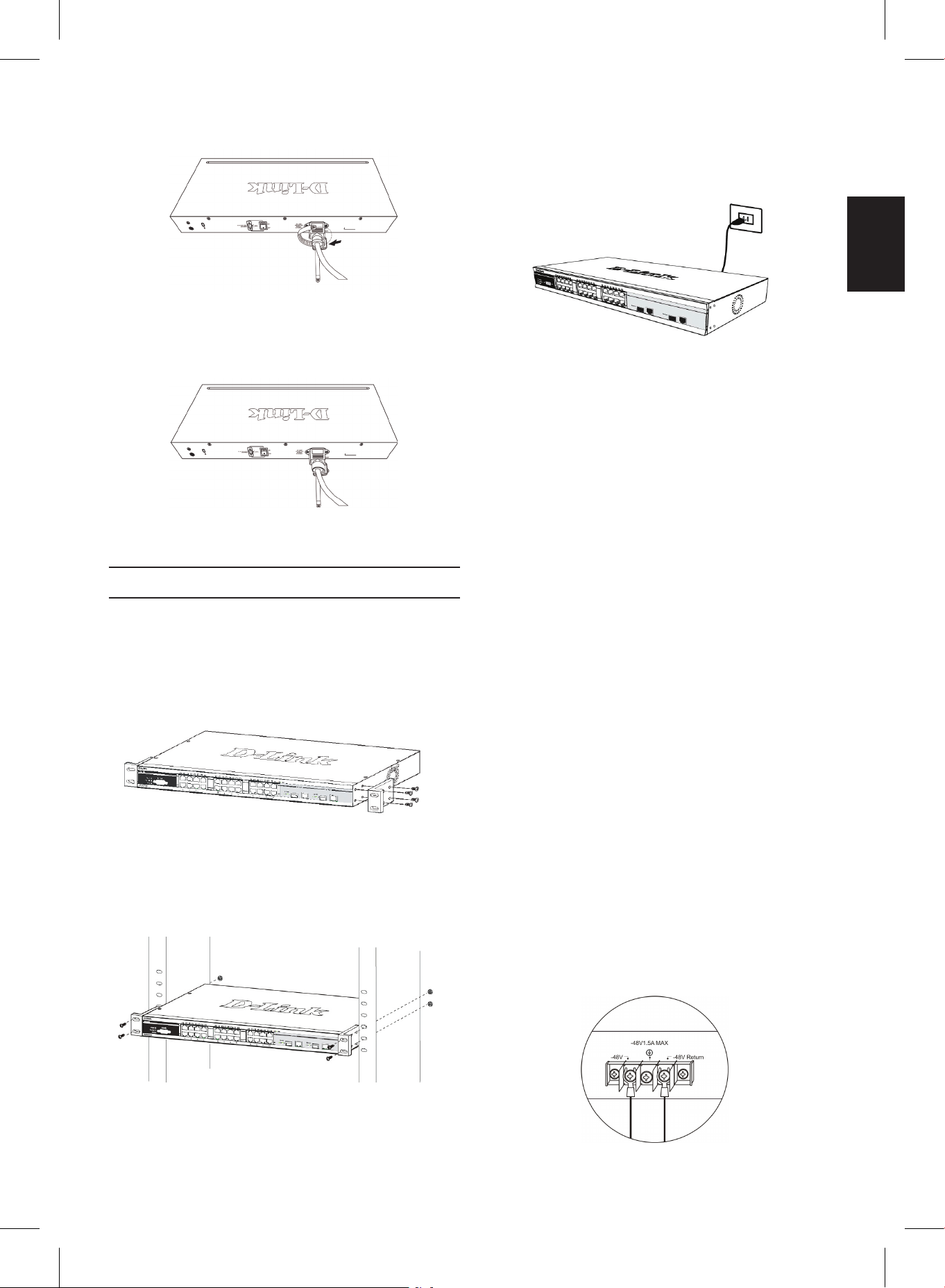
3. Slide the Retainer through the Tie Wrap until the end
of the cord.
Figure 2-3. Slide the Retainer through the Tie Wrap
3
ENGLISH
4. Circle the tie of the Retainer around the power cord
and into the locker of the Retainer.
Figure 2-4. Circle around the power cord
5. Fasten the tie of the Retainer until the power cord is
secured.
Figure 2-5. Secure the power cord
Rack Installation
The switch can be mounted in an EIA standard size
19-inch rack, which can be placed in a wiring closet with
other equipment. To install, attach the mounting brackets
to the switch’s side panels (one on each side) and
secure them with the screws provided (please note that
these brackets are not designed for palm size switches).
Figure 3-1. Attaching the mounting brackets
Then, use the screws provided with the equipment rack
to mount the switch in the rack.
Figure 3-2. Installing the switch in a standard-sized
equipment rack
Step 3 – Plugging in the AC
Power Cord
Users may now connect the AC power cord to an
electrical outlet (preferably one that is grounded and
surge protected) and into the rear of the switch.
Figure 4. Plugging the switch into an outlet
Power Failure
As a precaution, the switch should be unplugged in
case of power failure. When power is resumed, plug the
switch back in.
Connecting DC power to the DC
power supported Switch
Follow the instructions below to connect the DC power
supply of a DC powered switch to a DC power source.
Figure 5. Power connections attached to contacts on
assembly
Firmly attach the DC power to the negative and positive
contacts on the wiring assembly.
• The negative pole (-) connects to the -48V contact.
• The positive pole (+) connects to the -48V Return
contact.
• If available, the earth ground may be connected to
center contact post.
• Tighten the contact screws so the connection is
secure.
4
ENGLISH
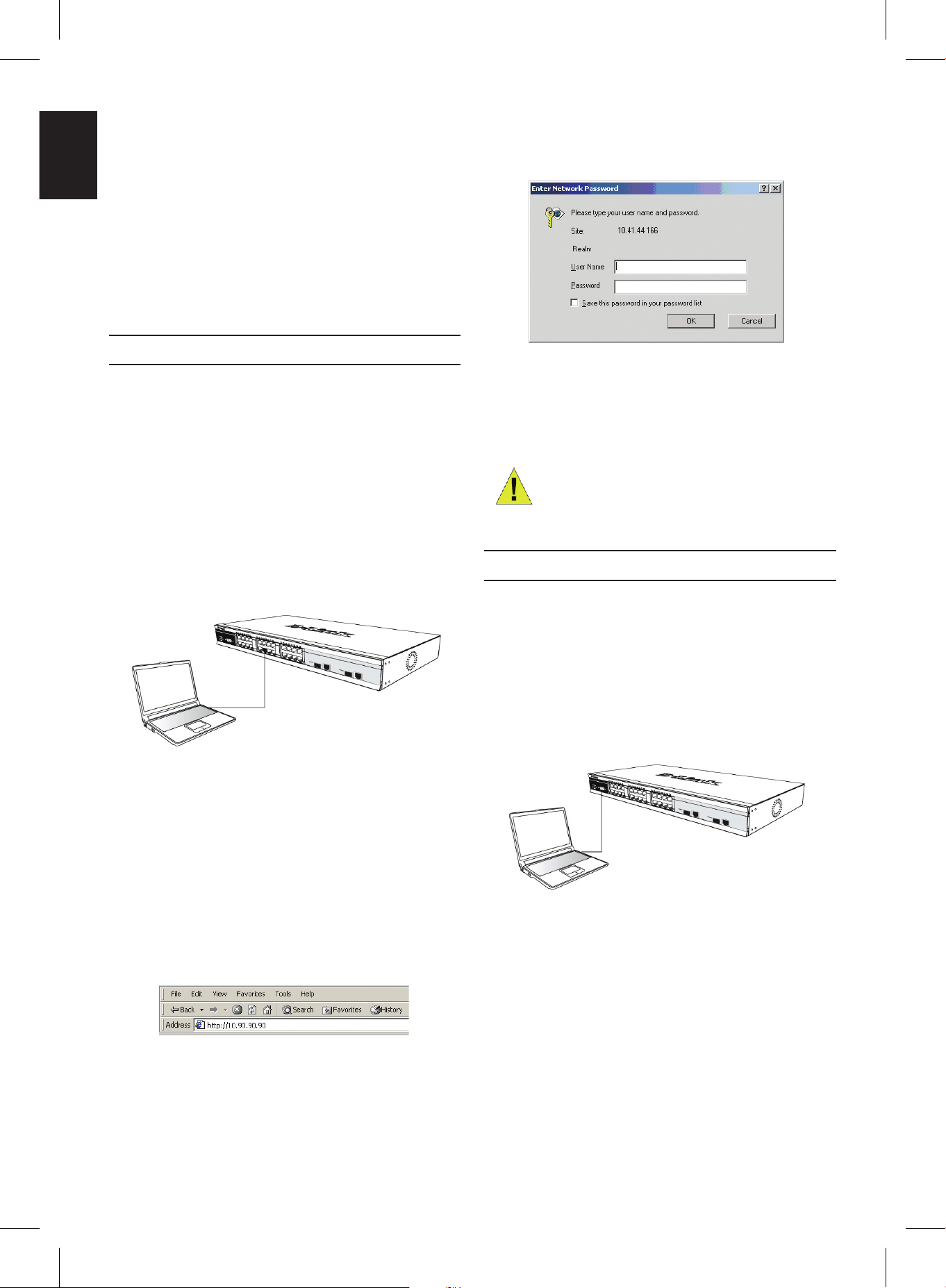
Management Options
This system may be managed out-of-band through
the console port on the front/back panel or in-band
using Telnet. The user may also choose the web-based
management, accessible through a web browser. Each
Switch must be assigned its own IP Address, which is
used for communication with an SNMP network manager
or other TCP/IP application (for example BOOTP, TFTP).
The Switch’s default IP address is 10.90.90.90. The user
can change the default Switch IP address to meet the
specication of your networking address scheme.
Web-based Management Interface
After a successful physical installation, you can congure
the Switch, monitor the LED panel, and display statistics
graphically using a web browser, such as Google Chrome
or Microsoft Internet Explorer.
The equipment you need to begin the web conguration
of your device:
• A PC with a RJ-45 Ethernet connection
• A standard Ethernet cable
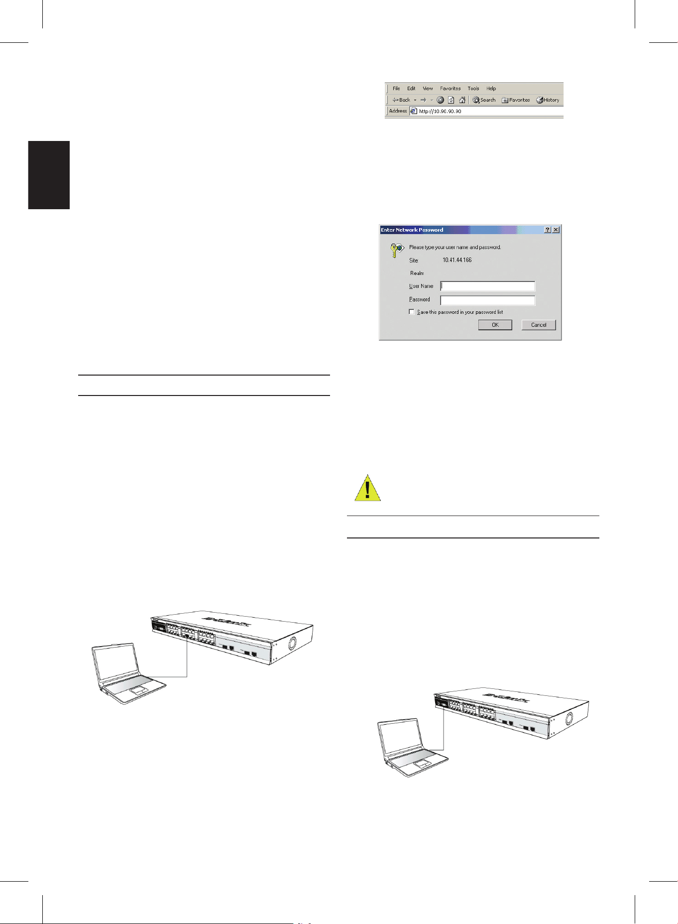
Step 1
Connect the Ethernet cable to any of the ports in front
panel of the switch and to the Ethernet port on the PC.
Figure 6-1. Connected to an end node via Ethernet
cable
Step 2
To begin managing your Switch, open the browser you
have installed on your computer and enter the IP address
of your device in the format http://xxx.xxx.xxx.xxx where
the xxx is a number between 1-255. For the user who
wants to access the device for the very rst time, enter the
factory default IP address 10.90.90.90, and press Enter.
Figure 6-2. Enter the IP address 10.90.90.90 in the
web browser
Step 3
This opens the management module’s user
authentication window, as seen below.
Figure 6-3. Enter Network Password window
Leave both the User Name eld and the Password eld
blank and click OK. This will open the Web-based user
interface.
NOTE: The Switch’s factory
default IP address is 10.90.90.90
with a subnet mask of 255.0.0.0
and a default gateway of 0.0.0.0.
Connecting the Console Port
The Switch provides an console port that enables a
connection to a computer or terminal for monitoring and
conguring the Switch. This port is implemented as a data
communication terminal equipment (DCE) connection.
To use the console port, you need the following equipment:
• A terminal or a computer with both a serial port and the
ability to emulate a terminal.
• A console cable to connect console port on the Switch.
Figure 7. Connected to an end node via console
cable
To connect a terminal to the console port:
1. Connect the console cable directly to the console port
on the Switch.
2. Connect the other end of the cable to a terminal or to
the serial connector of a computer running terminal
emulation software. Set the terminal emulation
software as follows:
5
ENGLISH
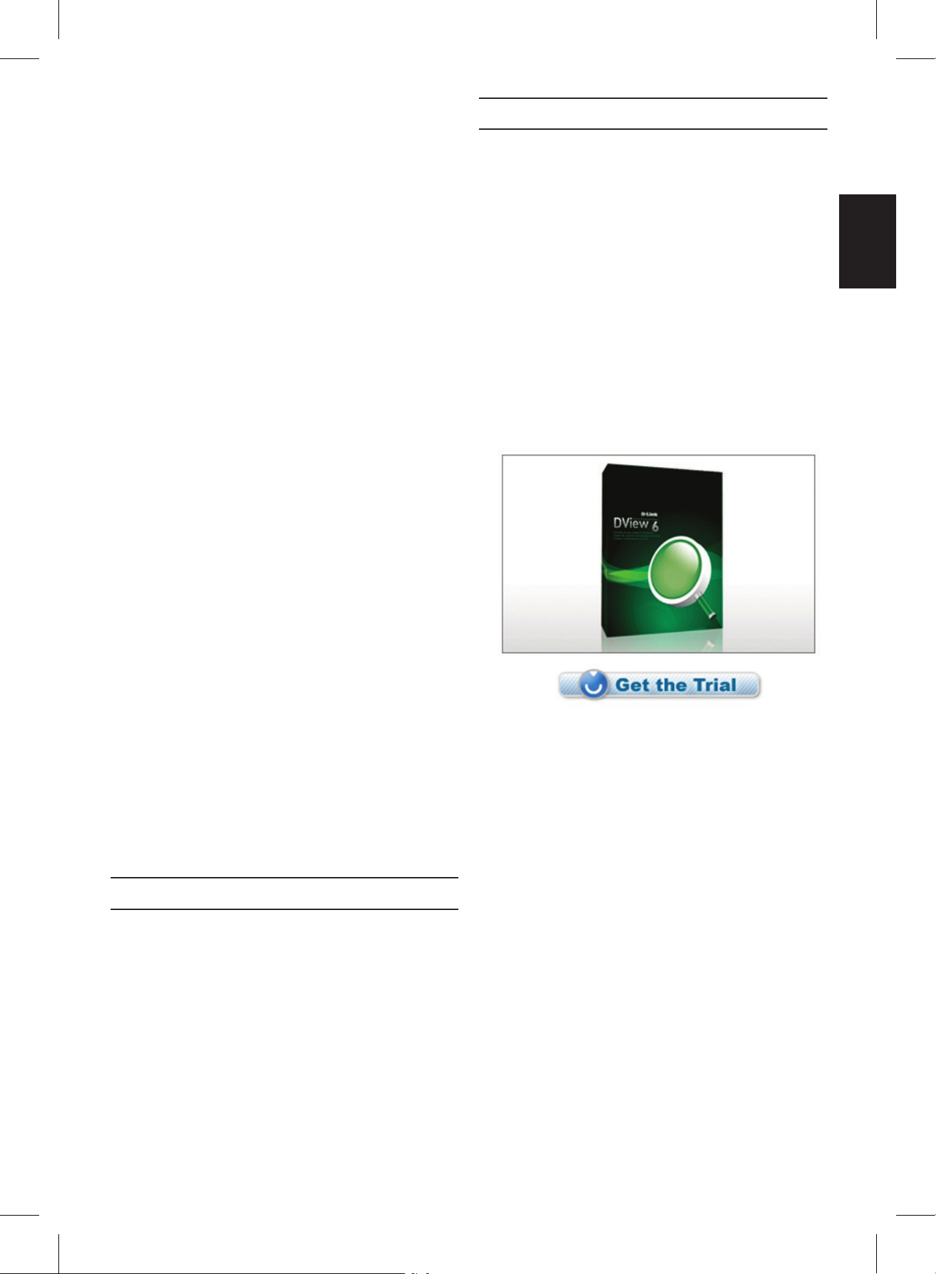
effectively manage device congurations, fault tolerance,
performance and security. D-Link offers free D-View trial
version download that allows you to free evaluate the
products for 30 days. You can download the trial version
from http://dview.dlink.com.tw/support_Download_Trial_
Version.asp
Additional Information
If you are encountering problems setting up your network,
please refer to the User’s Guide that came with the switch.
It contains many more rules, charts, explanations and
examples to help you get your network up and running.
Additional help is available through our ofces listed at the
back of the User’s Guide or online. To know more about
D-Link products or marketing information, please visit the
website http://www.dlink.com.
Warranty Information
The D-Link Limited Lifetime Warranty information is
available at http://warranty.dlink.com/
3. Select the appropriate port.
4. Set the data rate. (9600 or 115200)
5. Set the data format to 8 data bits, 1 stop bit, and no
parity.
6. Set ow control to none.
7. Under Properties, select VT100 for Emulation mode.
8. Select Terminal keys for Function, Arrow, and Ctrl
keys. Ensure that you select Terminal keys (not
Windows keys).
9. After you have correctly set up the terminal, plug the
power cable into the power receptacle on the back
of the Switch. The boot sequence appears in the
terminal.
10. After the boot sequence completes, the console login
screen displays.
11. If you have not logged into the command line
interface (CLI) program, press the Enter key at the
User name and password prompts. There is no
default user name and password for the Switch.
The administrator must rstly create user names
and passwords. If you have previously set up user
accounts, log in and continue to congure the Switch.
12. Enter the commands to complete your desired
tasks. Many commands require administrator-level
access privileges. See the Command Line Interface
Reference Manual on the documentation CD for a list
of all commands and additional information using the
CLI.
13. When you have completed your tasks, exit the
session with the logout command or close the
emulator program.
Telnet Management
Users may also access the switch console through Telnet
using your PC’s Command Prompt. To access it from your
computer, users must rst ensure that a valid connection
is made through the Ethernet port of the Switch and your
PC, and then click Start > Programs > Accessories >
Command Prompt on your computer. Once the console
window opens, enter the command telnet 10.90.90.90
(depending on congured IP address) and press Enter
on your keyboard. You should be directed to the opening
console screen for the Command Line Interface of
the switch, press the Enter key at the User name and
password prompts. There is no default user name and
password for the Switch.
SNMP-Based Management
You can manage the Switch with D-Link D-View or any
SNMP-compatible console program. The SNMP function
is default Disabled for D-Link managed switches.
D-View SNMP Network Management System is a
comprehensive standard-based management tool
designed to centrally manage critical network. D-View
provides useful tools to allow network administrators to
6
DEUTSCH
Einleitung
Diese Anleitung weist Sie Schritt für Schritt an, wie
Sie alle D-Link Managed Switches einrichten können
und bietet dem Produkt entsprechende Garantien,
Sicherheitshinweise, Hinweise zur Einhaltung rechtlicher
Vorschriften sowie zur Umweltverträglichkeit.
Beachten Sie, dass Ihr Modell sich möglicherweise
geringfügig von den Abbildungen unterscheidet.
Nähere Informationen über Ihren Switch und
seine Komponenten sowie zur Herstellung von
Netzwerkverbindungen und zu den entsprechenden
technischen Daten nden Sie im Benutzerhandbuch, das
Ihrem Switch beiliegt.
Schritt 1 – Auspacken
Öffnen Sie den Versandkarton und entnehmen Sie
vorsichtig den Inhalt. Überprüfen Sie die Unversehrtheit
und Vollständigkeit anhand der Liste des Lieferumfanges
im Handbuch. Falls etwas fehlen sollte oder beschädigt
ist wenden Sie sich bitte an Ihren D-Link Händler, um
Ersatz zu bekommen.
Inhalt der Switch Verpackung
Teil
Switch Typ
Unmanaged
Smart or
Managed
Desktop Rack Mount Chassis
Gerät Ja Ja Ja Ja
Konsolenkabel Nein Nein Ja Ja
Rack
Einbaumaterial
Nein Ja Ja Ja
Gummifüße Ja Ja Ja Ja
Stromkabel
(Netzteil)
Ja Ja Ja Ja
Mehrsprachige
Installationsanleitung
Ja Ja Ja Ja
Netzkabelhalter Nein Nein Ja Nein
CD Nein Nein Ja Ja
Schritt 2 – Installation
Um den Switch sicher zu installieren und in Betrieb
zunehmen, beachten Sie bitte die folgenden Hinweise:
• Vergewissern Sie sich, dass das Stromkabel fest in der
Stromeingangsbuchse steckt.
• Sorgen Sie für einen gute Wärmeableitung und
ausreichende Luftzirkulation am Aufstellungsort.
• Stellen Sie keine schweren Gegenstände auf den
Switch.
Tisch- oder Regal-Installation
Für die Tisch- oder Regal-Installation befestigen Sie
die mitgelieferten Gummifüße auf der Unterseite des
Switches an den vier Ecken. Sorgen Sie um den Switch
herum für ausreichende Belüftung.
Abbildung 1. Befestigung der Gummifüße
Anbringen einer Netzkabelhalter
Um ein versehentliches Entfernen des Stromkabels
zu verhindern, wird empfohlen, zusammen mit dem
Stromkabel die Netzkabelhalter anzubringen.
1. Stecken Sie den Kabelbinder mit der rauen
Seite nach unten in das Loch unterhalb der
Stromanschlussbuchse.
Abbildung 2-1. Kabelbinder in den Switch stecken
2. Stecken Sie das Wechselstromkabel in die Switch-
Anschlussbuchse.
Abbildung 2-2. Stromkabel an den Switch
anschließen
3. Führen Sie den Kabelhalter durch den Kabelbinder bis
zum Ende des Kabels.
Abbildung 2-3. Kabelhalter durch den Kabelbinder führen
7
DEUTSCH
4. Wickeln Sie das Kabelhalterband um das Stromkabel
und stecken Sie es in die Öse des Kabelhalters.
Abbildung 2-4. Stromkabel umwickeln
5. Ziehen Sie das Zugband der Kabelhalterung fest, bis
das Stromkabel sicher und fest angebracht ist.
Abbildung 2-5. Stromkabel sicher befestigen
Rack Installation
Der Rackmount-Switch kann in ein Standard 19-Zoll Rack
als Bestandteil der Netzwerkverkabelung zusammen mit
anderen Geräten eingebaut warden.Schrauben Sie die
Rackmontage-Winkel mit den mitglieferten Schrauben
vorne seitlich an den Switch (bitte beachten Sie, dass
Switches in Desktop-Größe diese Option nicht besitzen).
Abbildung 3-1. Befestigung der Rack-Einbauwinkel
Danach wird der Switch mit den zusammen mit dem
Rack gelieferten Schrauben eingebaut.
Abbildung 3-2. Einbau im Standard 19-Zoll Rack
Schritt 3 – Stromanschluss
Stecken Sie nun das Stromkabel in die Steckdose der
Stromversorgung. Eine abgesicherte Stromquelle mit
Schutzkontakt ist empfehlenswert.
Abbildung 4. Stromanschluss
Stromausfall
Bei Stromausfall sollte der Switch vorsorglich von der
Stromversorgung getrennt werden. Erst wenn der Strom
wieder da ist, sollte er wieder angeschlossen werden.
Schritt 4 – Netzwerkverbindungen
Computer, Server und Router können mit geeigneten
Netzwerkkabeln am Switch angeschlossen warden.
Nähere Information zu den verschiedenen Kabeltypen
entnehmen sie bitte dem Handbuch. Kurze Zeit nach dem
Einschalten sehen Sie, welche Netzwerkverbindungen
bestehen. Eine bestehende Netzwerkverbindung
erkennen Sie an der leuchtenden Link/Act LED des
jeweiligen Anschlusses (Port).
Weitere Informationen
Bei Problemen mit der Einrichtung des Netzwerkes
schauen Sie zuerst im Switch-Handbuch nach. Es enthält
viele weiteres Regeln, Übersichten, Erklärungen und
Beispiele zur erfolgreichen Einrichtung eines lokalen
Netzwerkes. Zusätzliche Hilfe erhalten Sie auch Online
auf http://www.dlink.de,http://www.dlink.at, http://www.
dlink.ch oder von den D-Link Niederlassungen, deren
Adressen auf der letzten Seite des Handbuches stehen.
Stromanschluss am Switch mit
Gleichspannungsnetzteil (DC)
Befolgen Sie die Anweisungen unten, um das
Gleichspannungsnetzteil eines DC-Switchmodelles an
eine Gleichspannungsquelle anzuschließen.
Abbildung 5. Montage der Stromanschlüsse an den
Kontakten
8
DEUTSCH
Verbinden Sie die Minus- und Pluskabel der
Stromversorgung fest mit den Kontakten des Netzteiles.
• Der Minuspol (-) wird mit dem -48V Kontakt verbunden.
• Der Pluspol (+) wird mit dem -48V Return Kontakt
verbunden.
• Falls ein Schutzkontakt (Erde) vorhanden ist, wird dieser
mit dem mittleren Kontakt verbunden.
• Ziehen Sie die Schrauben an den Kontakten fest an.
Management Optionen
Das Switch System kann von außen (out-of-band) über den
Konsolenanschluss auf der Vorder- oder Rückseite oder intern
(in-band) über TELNET verwaltet werden. Außerdem steht
intern noch das Web-basierte Management, das mit einem
Web-Browser geöffnet wird, zur Verfügung. Jedem Switch
muss eine eindeutige IPAdresse zugewiesen werden, die
zur Kommunikation mit einem SNMP Netzwerkmanagement
System oder für andere TCP/IP Anwendungen (z.B. BOOTP,
TFTP) benötigt wird. Die Werkseinstellung der IP-Adresse
des Switches ist 10.90.90.90. Diese IP-Adresse kann zur
Anpassung an die eigene Netzwerkadressierung geändert
werden.
Web-Management
Nach der physischen Geräteinstallation, können Sie mit der
Konfguration beginnen, die LED-Anzeigen überwachen und
Statistiken über einen Web-Browser graphisch anzeigen
lassen. Der Browser sollte die Mindestanforderungen
erfüllen wie das beim Google Chrome oder Microsoft Internet
Explorer.
Folgende Ausrüstung benötigen sie für das Web-
Management:
• Einen PC mit RJ-45 Ethernet Anschluss
• Ein Standard Ethernetkabel
Schritt 1
Verbinden Sie das Ethernetkabel mit einem beliebigen
Anschluss des Switches und mit dem Ethernetanschluss
des PCs.
Abbildung 6-1. Verbindung eines Endgerätes über
Ethernetkabel
Schritt 2
Öffnen Sie den Browser, der auf Ihrem Computer installiert
ist, und geben Sie die Web-Adresse Ihres Gerätes im
Format http://xxx.xxx.xxx.xxx ein, wobei xxx eine Zahl
zwischen 1 und 255 ist. Beim erstmaligen Kontakt zu dem
Switch mit Werkseinstellung verwenden Sie die Adresse
http://10.90.90.90 und klicken Sie auf Enter.
Abbildung 6-2. Eingabe der IP-Adresse 10.90.90.90 im
Web-Browser
Schritt 3
Es öffnet sich ein neues Fenster zur Benutzeranmeldung
wie abgebildet.
Abbildung 6-3. Eingabe des Kennwortes im
Anmeldefenster
Lassen die Felder User Name (Benutzername) und
Password (Kennwort) leer und klicken Sie auf OK. Danach
öffnet sich das Web-Management Menü.
Hinweis: Die Werkseinstellung
der IP-Adresse des Switches ist
10.90.90.90 mit der
Subnetzmaske 255.0.0.0 und
dem Default Gateway 0.0.0.0.
Verbindung über den Konsolenanschluss
Der Switch besitzt einen Konsole Anschluss, der die
Überwachung und die Konguration über einen Computer
oder ein Terminal von außen ermöglicht. Dieser Anschluss
hat die als Datenübertragungseinrichtung (DCE) ausgelegt
ist.
Folgende Ausrüstung wird zur Verwendung des
Konsolenanschlusses benötigt:
• Ein Terminal mit seriellem Anschluss oder ein PC mit
seriellem Anschluss und einer Terminalemulation.
• Ein Konsolenkabel zur Verbindung mit dem Konsolen-Port
am Switch.
Abbildung 7. Endgerät verbunden über ein
Konsolenkabel
9
DEUTSCH
So verbinden Sie ein Terminal über den
Konsolenanschluss:
1.Verbinden Sie die Konsole-Kabel direkt an den Konsolen-
Port auf dem Switch.
2.Verbinden Sie das andere Ende des Kabels mit dem
seriellen Anschluss eines Terminals oder eines PCs
mit Terminalemulation. Stellen Sie die Parameter der
Terminalemulation wie folgt ein:
3.Wählen Sie den richtigen Anschluss.
4.Stellen Sie die Datenrate ein. (9600 or 115200)
5.Stellen Sie das Datenformat auf 8 Bit, 1 Stop-Bit, keine
Parität.
6.Schalten Sie die Flußkontrolle aus.
7.Stellen Sie in den Eigenschaften VT100 Emulation ein.
8.Wählen Sie die Terminal-Tastenbelegung für Funktions-,
Pfeil- und Steuerungstasten aus. Die Windows-
Tastenbelegung darf nicht aktiviert sein.
9.Nach der korrekten Einrichtung und dem Start des
Terminals stecken Sie das Stromkabel in die Buchse des
Switchnetzteiles. Die Meldungen des Bootvorganges
erscheinen im Terminal.
10.Nach dem Abschluss des Bootvorganges wird die
Konsolenanmeldung angezeigt.
11.Wenn Sie sich zum ersten Mal am
Kommandozeilenprogramm (CLI) anmelden, drücken
Sie bei den Eingabeaufforderungen User Name
(Benutzername) und Password (Kennwort) einfach nur
Enter. Erst wenn der Administrator Benutzernamen und
Kennwörter eingerichtet hat, müssen Sie an dieser Stelle
Ihren Benutzernamen und Ihr Kennwort eingeben, um den
Switch kongurieren und überwachen zu können.
12.Geben Sie nun am Prompt die entsprechenden Befehle
ein. Viele Kommandos erfordern Administratorrechte. Im
elektronischen CLIReferenzhandbuch auf der CD nden
Sie die Beschreibung aller Kommandos und weitere
wichtige Informationen.
13.Wenn sie fertig sind, beenden Sie die Sitzung mit dem
Befehl Logout (Abmeldung) und schließen Sie das
Terminalprogramm.
TELNET Management
Die Switch-Kommandozeile kann intern auch über TELNET
und die Eingabeaufforderung des PCs erreicht werden.
Dafür muss zunächst eine Ethernetverbindung vom PC zum
Switch aufgebaut sein. Öffnen Sie die Eingabeaufforderung
Ihres Computers (z.B. in Windows über Start > Programme
> Zubehör > Eingabeaufforderung). Am Prompt geben
Sie den Befehl telnet 10.90.90.90 (Werkseinstellung der
Switch IPAdresse) ein und drücken dann auf Enter. Sie
sollten nun die Eingabeaufforderung zur Anmeldung am
Kommandozeilenprogramm des Switches erreicht haben.
drücken Sie bei User Name (Benutzername) und Password
(Kennwort) einfach nur Enter In der Werkseinstellung gibt es
noch keine Benutzernamen und Kennwörter.
SNMP Netzwerkmanagement
Der Switch kann mit dem D-Link D-View SNMP
Netzwerkmanagement oder einer anderen
SNMPkompatiblen Management Software. Das SNMP
Protokoll ist in der Werkseinstellung der D-Link Managed
Switches ausgeschaltet.
Bei dem D-View SNMP Network Management System handelt
es sich um ein umfassendes, auf entsprechenden Standards
basierendes Management Tool, das einer unternehmens-
und geschäftskritischen zentralen Netzwerkverwaltung
dient. D-View bietet nützliche Funktionen, die
Netzwerkadministratoren die effektive Durchführung und
Verwaltung von Gerätekongurationen, Fehlertoleranzen,
Performance- und Sicherheitsoptionen ermöglichen. D-Link
stellt Ihnen D-View als kostenlose Testversion zur freien
Beurteilung des Produkts für den Zeitraum von 30 Tagen zur
Verfügung. Sie können die Testversion hier herunterladen:
http://dview.dlink.com.tw/support_Download_Trial_Version.
asp
Weitere Informationen
Wenn beim Einrichten Ihres Netzwerks Probleme auftreten
sollten, schlagen Sie bitte im Benutzerhandbuch nach, das
mit dem Switch geliefert wurde. Hier nden Sie weitere
Regeln, Diagramme, Erläuterungen und Beispiele, die Ihnen
bei der Inbetriebnahme Ihres Netzwerks helfen.
Weitere Hilfe und Unterstützung steht Ihnen von unseren
auf der Rückseite des Benutzerhandbuchs aufgeführten
Niederlassungen oder online zur Verfügung. Wenn Sie
an weiteren Einzelheiten zu den Produkten oder an
Marketinginformationen von D-Link interessiert sind,
besuchen Sie bitte die Website http://www.dlink.com
Garantiebestimmungen
Informationen zur eingeschränkten Garantie auf Lebenszeit
für Produkte von D-Link nden Sie unter http://warranty.dlink.
com/
10
FRANÇAIS
Introduction
Ce guide contient des instructions détaillées concernant
la conguration de tous les commutateurs gérés par
D-Link, ainsi que les déclarations de garantie, sécurité,
règlementaires et environnementales correspondantes.
Notez que le modèle que vous avez acheté peut
légèrement différer de celui illustré sur les gures.
Pour de plus amples informations sur votre commutateur,
ses composants, sa connexion au réseau et ses
caractéristiques techniques, veuillez consulter le Guide
d’utilisation associé.
Étape 1 : déballage
Ouvrez le carton d’expédition et sortez-en le contenu
avec précaution. Le Guide de l’utilisateur contient une
liste des éléments devant se trouver dans l’emballage
; en vous y reportant, vériez que tous les composants
sont présents et en parfait état. Si un élément est absent
ou détérioré, contactez votre revendeur D-Link pour en
obtenir un nouveau.
Éléments contenus dans l’emballage d’un switch
Élément
Type de switch
Non
administrable
Smart ou
administrable
Palm
De bureau/à
monter
en armoire
Châssis
Appareil
Oui Oui Oui Oui
Câble console
Non Non Oui Oui
Supports pour
montage en
armoire
Non Oui Oui Oui
Pieds en
caoutchouc
Oui Oui Oui Oui
Cordon
d’alimentation
(adaptateur)
Oui Oui Oui Oui
Guide de mise en
route
(multilingue)
Oui Oui Oui Oui
Le cordon
d’alimentation de
retenue
Non Non Oui Non
CD
Non Non Oui Oui
Étape 2 : installation du switch
Pour installer et utiliser le switch en toute sécurité, nous
vous recommandons de procéder comme suit :
• Inspectez visuellement le cordon d’alimentation et
assurez-vous du parfait assujettissement du connecteur
d’alimentation secteur.
• Vériez que le switch présente une dissipation de chaleur
adaptée et qu’il est entouré d’un espace sufsant pour
garantir une bonne ventilation.
• Ne posez pas d’objets lourds sur le switch.
Installation sur un bureau ou une étagère
Pour installer le switch sur un bureau ou une étagère,
vous devez lui ajouter les pieds en caoutchouc fournis,
aux quatre coins de sa base. À des ns de ventilation,
prévoyez un espace sufsant entre l’appareil et les
objets environnants.
Figure 1. Fixation des pieds en caoutchouc
Installation Cordon de retenue
An d’éviter tout débranchement accidentel du cordon
d’alimentation secteur, il est recommandé d’installer le
dispositif de retenue du cordon d’alimentation en même
temps que le cordon.
1. Avec le côté rugueux tourné vers le bas, insérez le
collier de serrage dans le trou situé sous la prise
d’alimentation.
Figure 2.-1. Insérez le collier de serrage dans le
commutateur
2. Branchez le cordon d’alimentation secteur dans la
prise d’alimentation du commutateur.
Figure 2.-2. Connectez le cordon d’alimentation au
commutateur.
 Loading...