


DGS-1510-28X
Getting Started Guide
Краткое руководство по установке
DGS-1510-28X
Layer 2+ SmartPro Stackable Switch with 24 10/100/1000Base-T Ports
and 4 10GBase-X SFP+ Ports
Настраиваемый стекируемый коммутатор SmartPro уровня 2+
с 24 портами 10/100/1000Base-T и 4 портами 10GBase-X SFP+
About This Guide
This guide gives step-by-step instructions for setting up
ENGLISH
switches and relative Warranty, Safety, Regulatory, and
Environment Notice. Please note that the model you
have purchased may appear slightly different from those
shown in the illustrations.
For more detailed information about your switch, its
components, making network connections, and technical
specications, please refer to the User’s Guide included
with your switch.
Step 1 – Unpacking
Open the shipping carton and carefully unpack its
contents. Please consult the packing list located in the
User Guide to make sure all items are present and
undamaged. If any item is missing or damaged, please
contact your local D-Link reseller for replacement.
- One D-Link Switch
- Rack mounting bracket
- Rubber feet
- Power cord
- Power cord retainer
- Console cable
- User’s Guide CD with DNA (D-Link Network Assistant)
program
- One multilingual Getting Started Guide
- An accessory kit for one ground screw
Step 2 – Switch Installation
For safe switch installation and operation, it is
recommended that you:
• Visually inspect the power cord to see that it is secured
fully to the AC power connector.
• Make sure that there is proper heat dissipation and
adequate ventilation around the switch.
• Do not place heavy objects on the switch
Grounding the Switch (depending on
the purchased model)
This section describes how to connect the Switch to
ground. You must complete this procedure before
powering on your Switch.
Required Tools and Equipment
• Grounding screws (included in the accessory kit):
One M4 x 6 mm (metric) pan-head screw
• Grounding cable (not included in the accessory kit):
The grounding cable should be sized according
to local and national installation requirements.
Depending on the power supply and system, a
12 to 6 AWG copper conductor is required for
installation. Commercially available 6 AWG wire is
recommended. The length of the cable depends
on the proximity of the Switch to proper grounding
facilities.
• A screwdriver (not included in the accessory kit)
You can connect the Switch to a protective ground by
following the steps below:
1. Verify if the system power is off.
2. Use the grounding cable to place the #8 terminal
lug ring on top of the ground-screw opening.
3. Insert the grounding screw into the ground-screw
opening.
4. Using a screwdriver, tighten the grounding screw to
secure the grounding cable to the Switch.
5. Attach the terminal lug ring at the other end of the
grounding cable to an appropriate grounding stud or
bolt on rack where the Switch is installed.
6. Verify if the connections at the ground connector on
the Switch and the rack are securely attached.
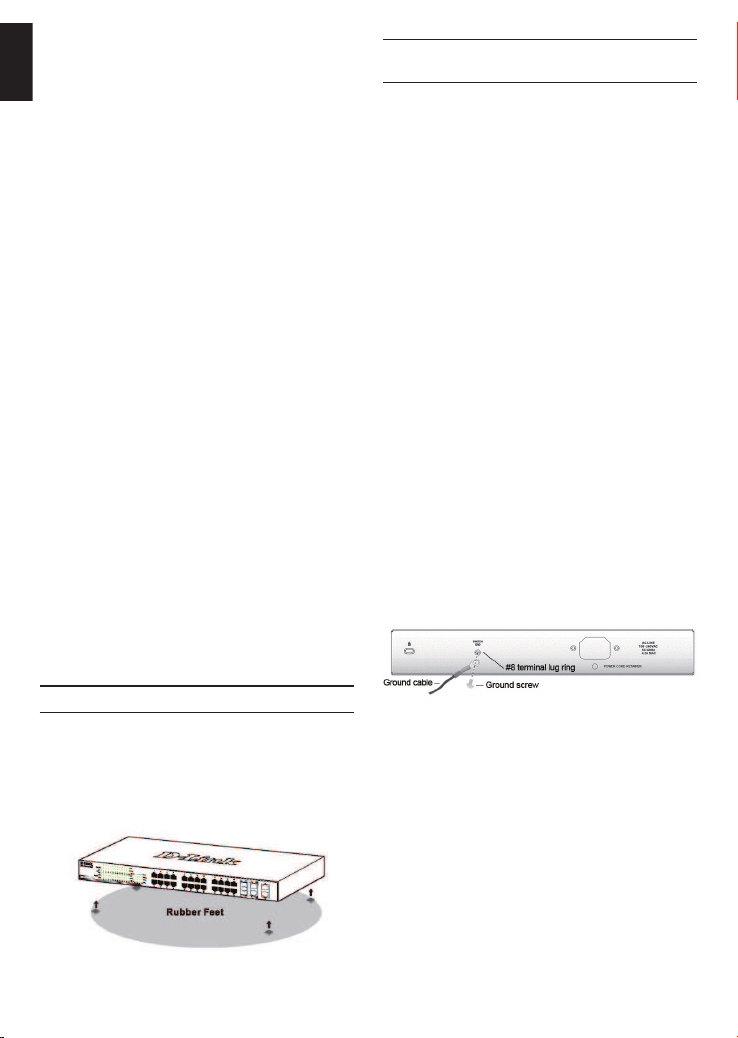
Desktop or Shelf Installation
When installing the switch on a desktop or shelf, the
rubber feet included with the device must be attached
on the bottom at each corner of the device’s base. Allow
enough ventilation space between the device and the
objects around it.
Figure 1. Attaching the rubber feet
2
Figure 2. Connect a Grounding Cable
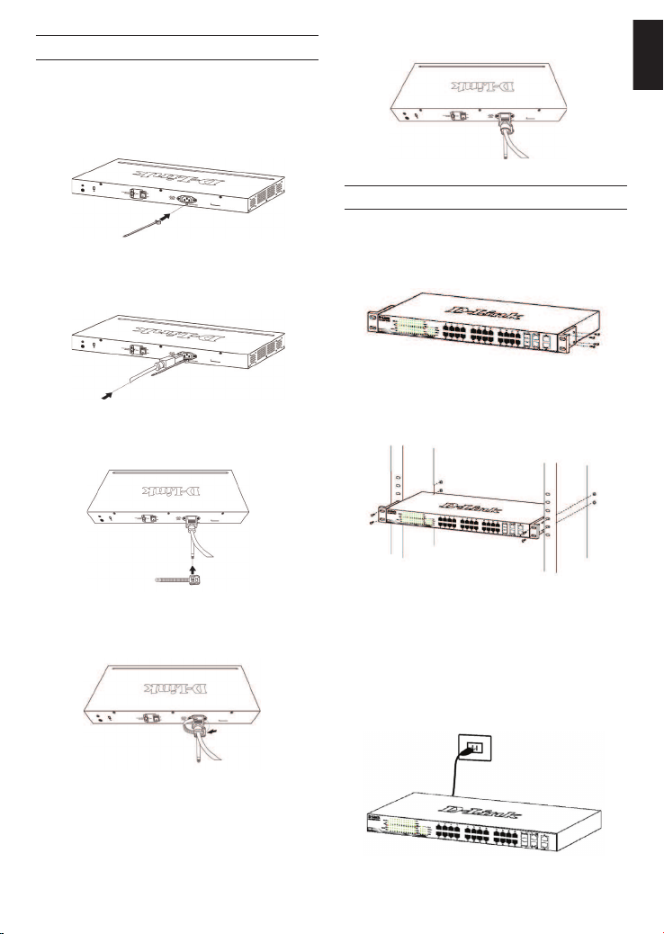
Installing Power Cord Retainer
To prevent accidental removal of the AC power cord, it is
recommended to install the power cord retainer together
with the power cord.
1. With the rough side facing down, insert the Tie Wrap
into the hole below the power socket.
Figure 3-1. Insert Tie Wrap to the Switch
2. Plug the AC power cord into the power socket of the
Switch.
5. Fasten the tie of the Retainer until the power cord is
secured.
Figure 3-5. Secure the power cord
Rack Installation
The switch can be mounted in an EIA standard size
19-inch rack, which can be placed in a wiring closet with
other equipment. To install, attach the mounting brackets
to the switch’s side panels (one on each side) and
secure them with the screws provided.
Figure 4. Attaching the mounting brackets
ENGLISH
Figure 3-2. Connect the power cord to the Switch
3. Slide the Retainer through the Tie Wrap until the end
of the cord.
Figure 3-3. Slide the Retainer through the Tie Wrap
4. Circle the tie of the Retainer around the power cord
and into the locker of the Retainer.
Figure 3-4. Circle around the power cord
Then, use the screws provided with the equipment rack
to mount the switch in the rack.
Figure 5. Installing the switch in a standard-sized
equipment rack
Step 3 – Plugging in the AC
Power Cord
You can now connect the AC power cord into the rear of
the switch and to an electrical outlet (preferably one that
is grounded and surge protected).
Figure 6. Plugging the switch into an outlet
3
Power Failure
As a precaution, the switch should be unplugged in
case of power failure. When power is resumed, plug the
ENGLISH
switch back in.
Management Options
This system may be managed out-of-band through the
console port on the front/back panel or in-band using
Telnet. The user may also choose the web-based
management, accessible through a web browser. Each
Switch must be assigned its own IP Address, which is
used for communication with an SNMP network manager
or other TCP/IP application (for example BOOTP, TFTP).
The Switch’s default IP address is 10.90.90.90. The user
can change the default Switch IP address to meet the
specication of your networking address scheme.
Web-based Management Interface
After a successful physical installation, you can congure
the switch, monitor the LED panel, and display statistics
graphically using a web browser, such as Microsoft®
Internet Explorer version 7.0 and higher, Firefox, Chrome
or Safari.
You need the following equipment to begin the web
conguration of your device:
• A PC with a RJ-45 Ethernet connection
• A standard Ethernet cable
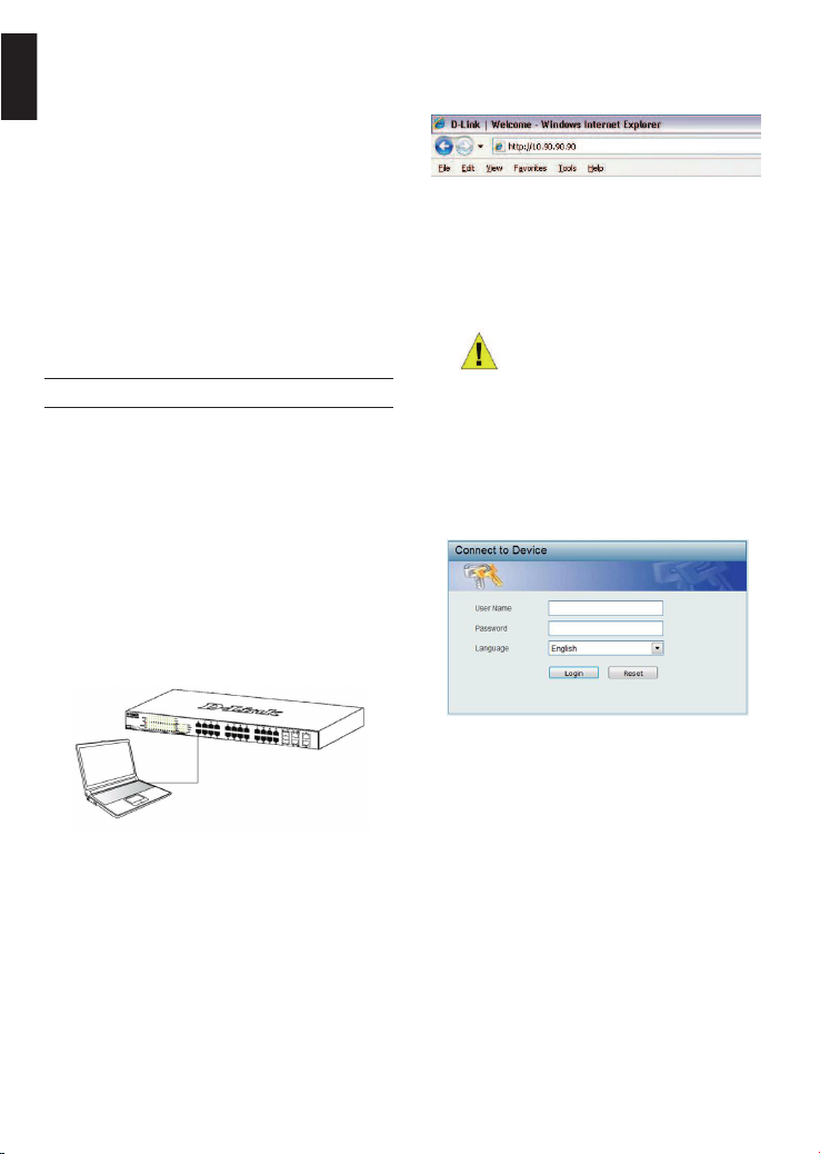
Step 1
Connect the Ethernet cable to any of the ports in front
panel of the switch and to the Ethernet port on the PC.
Open your web browser and enter http://10.90.90.90
(the factory-default IP address) in the address box. Then
press <Enter>.
Figure 8. Enter the IP address 10.90.90.90 in the web
browser
The web conguration can also be accessed through the
DNA. You can click the IP hyper link in the device list in
the DNA to open the web GUI of devices.
NOTE: The switch’s factory default IP
address is 10.90.90.90 with a subnet
mask of 255.0.0.0 and a default
gateway of 0.0.0.0
Step 3
When the following logon dialog box appears, enter
“admin” for both the Username and Password and
choose the language of the Web-based Management
interface then click Login.
Figure 7. Connected Ethernet cable
Step 2
In order to login and congure the switch via an Ethernet
connection, the PC must have an IP address in the same
range as the switch. For example, if the switch has an
IP address of 10.90.90.90, the PC should have an IP
address of 10.x.y.z (where x/y is a number between 0 ~
254 and z is a number between 1 ~254), and a subnet
mask of 255.0.0.0.
4
Figure 8. Enter Network Password window
Step 4
Before entering the Web-based Management, the
Smart Wizard will guide you to quickly congure some
functions, such as Ip Information, User Account and
SNMP Settings. If you don’t plan to change anything,
click Exit to exit the Wizard and enter the Web-based
Management. For a detailed look at the Smart Wizard’s
functions, please refer to the Smart Wizard introduction
in the user manual.
 Loading...