


DGS-1100-10

D-Link DGS-1100-10/ME User Manual
Table of Contents
Table of Contents ............................................................................................................................................. i
About This Guide ............................................................................................................................................. 1
Terms/Usage .................................................................................................................................................. 1
Copyright and Trademarks ............................................................................................................................ 1
1 Product Introduction ................................................................................................................................... 2
DGS-1100-10/ME ........................................................................................................................................... 2
Front Panel ................................................................................................................................................. 2
Rear Panel .................................................................................................................................................. 2
2 Hardware Installation .................................................................................................................................. 3
Step 1: Unpacking .......................................................................................................................................... 3
Step 2: Switch Installation .............................................................................................................................. 3
Desktop or Shelf Installation ....................................................................................................................... 3
Wall-mount ................................................................................................................................................. 3
Step 3 – Plugging in the AC Power Cord ....................................................................................................... 4
Power Failure ............................................................................................................................................. 4
3 Getting Started ............................................................................................................................................. 6
Management Options ..................................................................................................................................... 6
Using Web-based Management .................................................................................................................... 6
Supported Web Browsers .......................................................................................................................... 6
Connecting to the Switch ............................................................................................................................ 6
Login Web-based Management ................................................................................................................. 6
4 Configuration ............................................................................................................................................. 15
Web-based Management ............................................................................................................................. 15
Tool Bar > Save Menu ................................................................................................................................. 16
Save Configuration ................................................................................................................................... 16
Save Log .................................................................................................................................................. 16
Tool Bar > Tool Menu .................................................................................................................................. 16
Reset System ........................................................................................................................................... 16
Reboot Device .......................................................................................................................................... 16
Configuration Backup & Restore .............................................................................................................. 17
System Log Backup.................................................................................................................................. 17
Firmware Backup & Upgrade ................................................................................................................... 18
Tool Bar > Online Help ................................................................................................................................. 18
Function Tree ............................................................................................................................................... 19
Device Information.................................................................................................................................... 19
System > System Settings ....................................................................................................................... 20
System > DHCP Auto Configuration ........................................................................................................ 20
System > Port Configuration > Port Settings ........................................................................................... 21
System > Port Configuration > Port Description ...................................................................................... 22
System > Port Configuration > Port Error Disabled ................................................................................. 22
System > IPv6 Settings > IPv6 System Settings ...................................................................................... 22
System > IPv6 Settings > IPv6 Default Gateway Settings ....................................................................... 23
System > IPv6 Settings > IPv6 Neighbor Settings ................................................................................... 23
System > SNMP Settings > SNMP Global State ..................................................................................... 24
System > SNMP Settings > SNMP User Table ........................................................................................ 24
System > SNMP Settings > SNMP Group Table ..................................................................................... 25
System > SNMP Settings > SNMP View Table ....................................................................................... 25
i

D-Link DGS-1100-10/ME User Manual
System > SNMP Settings > SNMP Community Table ............................................................................. 26
System > SNMP Settings > SNMP Host Table ........................................................................................ 26
System > SNMP Settings > SNMP Engine ID ......................................................................................... 26
System > SNMP Settings > SNMP Trap Settings .................................................................................... 27
System > User Accounts .......................................................................................................................... 27
System > MAC Address Aging Time ........................................................................................................ 27
System > ARP Aging Time Settings ......................................................................................................... 28
System > PPPoE Circuit ID Insertion Settings ......................................................................................... 28
System > Web Settings ............................................................................................................................ 28
System > Telnet Settings ......................................................................................................................... 29
System > D-Link Discover Protocol Settings ............................................................................................ 29
System > Ping Test .................................................................................................................................. 29
System >Trace Route ............................................................................................................................... 30
System > MAC Notification Settings ........................................................................................................ 30
System > System Log Configuration > System Log Settings .................................................................. 31
System > System Log Configuration > System Log Server ..................................................................... 31
System > Time Profile .............................................................................................................................. 32
System > Power Saving ........................................................................................................................... 32
System > IEEE802.3az EEE Settings ...................................................................................................... 33
Configuration > 802.1Q VLAN .................................................................................................................. 34
Configuration > 802.1Q Management VLAN............................................................................................ 36
Configuration > 802.1Q VLAN PVID ........................................................................................................ 36
Configuration > QinQ > QinQ Settings ..................................................................................................... 36
Configuration > IGMP Snooping > IGMP Snooping ................................................................................. 37
Configuration > IGMP Snooping > IGMP Access Control Settings .......................................................... 38
Configuration > IGMP Snooping > Host Table ......................................................................................... 39
Configuration > MLD Snooping > MLD Snooping Settings ...................................................................... 39
Configuration > MLD Snooping > MLD Host Table .................................................................................. 40
Configuration > ISM VLAN Settings ......................................................................................................... 40
Configuration > Jumbo Frame .................................................................................................................. 41
Configuration > Port Mirroring .................................................................................................................. 42
Configuration > Loopback Detection ........................................................................................................ 42
Configuration > SNTP Settings > Time Settings ...................................................................................... 43
Configuration > SNTP Settings > TimeZone Settings .............................................................................. 43
Configuration > DHCP Relay > DHCP Relay Global Settings ................................................................. 44
Configuration > DHCP Relay > DHCP Relay Interface Settings .............................................................. 45
Configuration > DHCP Local Relay Settings ............................................................................................ 46
Configuration > DHCPv6 Relay Settings .................................................................................................. 46
Configuration > 802.3ah EthernetLink OAM > Ethernet OAM Port Settings............................................ 47
Configuration > 802.3ah EthernetLink OAM > Ethernet OAM Event Configuration ................................ 47
Configuration > DULD > DULD Port Settings .......................................................................................... 48
Configuration > Multicast Forwarding & Filter > Multicast Forwarding ..................................................... 49
Configuration > Multicast Forwarding & Filter > Multicast Filter Mode ..................................................... 49
Configuration > Multicast Forwarding & Filter > IP Multicast Profile Settings .......................................... 50
Configuration > Multicast Forwarding & Filter > Limited Multicast Range Settings ................................. 50
Configuration > Multicast Forwarding & Filter > Max Multicast Group Settings ....................................... 51
QoS > Traffic Control ................................................................................................................................ 51
QoS > Bandwidth Control ......................................................................................................................... 53
QoS > QoS Settings ................................................................................................................................. 53
ii

D-Link DGS-1100-10/ME User Manual
RMON > RMON Basic Settings................................................................................................................ 54
RMON > RMON Ethernet Statistics Configuration ................................................................................... 54
RMON > RMON History Control Configuration ........................................................................................ 54
RMON > RMON Alarm Configuration ...................................................................................................... 55
RMON > RMON Event Configuration ....................................................................................................... 56
Security > Safeguard Engine.................................................................................................................... 56
Security > Port Security > Port Security Settings ..................................................................................... 56
Security > Port Security > Port Security FDB Entry ................................................................................. 57
Security > 802.1X > 802.1X Settings ....................................................................................................... 57
Security > 802.1X > 802.1X User ............................................................................................................. 59
Security > 802.1X > Radius Accounting Settings .................................................................................... 59
Security > 802.1X > 802.1X Authentication RADIUS ............................................................................... 59
Security > 802.1X > 802.1X Guest VLAN ................................................................................................ 60
Security > MAC Address Table > Static MAC .......................................................................................... 60
Security > MAC Address Table > Dynamic Forwarding Table ................................................................. 62
Security > Access Authentication Control > Authentication Policy Settings ............................................ 63
Security > Access Authentication Control > Application Authentication Settings .................................... 63
Security > Access Authentication Control > Authentication Server Group .............................................. 63
Security > Access Authentication Control > Authentication Server ......................................................... 64
Security > Access Authentication Control > Login Method Lists .............................................................. 65
Security > Access Authentication Control > Enable Method Lists ........................................................... 65
Security > Access Authentication Control > Local Enable Password Settings ........................................ 66
Security > Traffic Segmentation ............................................................................................................... 66
Monitoring > Statistics .............................................................................................................................. 67
Monitoring > Session Table ...................................................................................................................... 68
Monitoring > CPU Utilization .................................................................................................................... 68
Monitoring > Memory Utilization ............................................................................................................... 68
Monitoring > Port Utilization ..................................................................................................................... 69
Monitoring > Packet Size .......................................................................................................................... 70
Monitoring > Packets > Transmitted (TX) ................................................................................................ 71
Monitoring > Packets > Received (RX) .................................................................................................... 72
Monitoring > Packets > UMB Cast (RX) ................................................................................................... 74
Monitoring > Errors > Received (RX) ....................................................................................................... 75
Monitoring > Errors > Transmitted (TX).................................................................................................... 76
Monitoring > Cable Diagnostics ............................................................................................................... 78
Monitoring > System Log .......................................................................................................................... 78
Monitoring > Browse ARP Table .............................................................................................................. 79
Monitoring > Ethernet OAM > Browse Ethernet OAM Event Log ............................................................ 79
Monitoring > Ethernet OAM > Browse Ethernet OAM Statistics .............................................................. 80
Monitoring > Port Access Control > RADIUS Authentication ................................................................... 80
Monitoring > Port Access Control > RADIUS Account Client .................................................................. 82
LLDP > LLDP Global Settings .................................................................................................................. 82
LLDP > Basic LLDP Port Settings ............................................................................................................ 83
LLDP > 802.1 Extension LLDP Port Settings ........................................................................................... 84
LLDP > 802.3 Extension LLDP Port Settings ........................................................................................... 84
LLDP > LLDP Management Address Settings ......................................................................................... 85
LLDP > LLDP Statistics Table .................................................................................................................. 85
LLDP > LLDP Management Address Table ............................................................................................. 86
LLDP > LLDP Local Port Table ................................................................................................................ 87
iii

D-Link DGS-1100-10/ME User Manual
LLDP > LLDP Remote Port Table ............................................................................................................ 88
Appendix A - Ethernet Technology ............................................................................................................ 109
Gigabit Ethernet Technology ..................................................................................................................... 109
Fast Ethernet Technology .......................................................................................................................... 109
Switching Technology ................................................................................................................................ 109
Appendix B - Technical Specifications ..................................................................................................... 110
Hardware Specifications ............................................................................................................................ 110
Key Components / Performance ............................................................................................................ 110
Port Functions ........................................................................................................................................ 110
Physical & Environment ......................................................................................................................... 110
Emission (EMI) Certifications ................................................................................................................. 110
Safety Certifications................................................................................................................................ 110
Features ..................................................................................................................................................... 110
L2 Features ............................................................................................................................................ 110
VLAN ...................................................................................................................................................... 110
QoS (Quality of Service) ......................................................................................................................... 110
Security ................................................................................................................................................... 111
OAM ....................................................................................................................................................... 111
Management ........................................................................................................................................... 111
D-Link Green Technology ...................................................................................................................... 111
Appendix C – Rack mount Instructions .................................................................................................... 112
iv

11
Note: The model you have purchased may
appear slightly different from the illustrations
shown in the document. Refer to the Product
Instruction and Technical Specification sections
for detailed information about your switch, its
components, network connections, and technical
specifications.
A NOTE indicates important information that
helps a better use of the device.
A CAUTION indicates potential property damage
or personal injury.
D-Link DGS-1100-10/ME User Manual
About This Guide
This guide provides instructions to install the D-Link Metro Ethernet Switch DGS-1100-10/ME and to
configure with HTTP step-by-step.
This guide is mainly divided into three parts:
1. Hardware Installation: Step-by-step hardware installation procedures.
2. Getting Started: A startup guide for basic switch installation and settings.
3. Configuration: Information about the function descriptions and configuration settings.
Terms/Usage
In this guide, the term “Switch” (first letter capitalized) refers to DGS-1100-10/ME, and “switch” (first letter
lower case) refers to other Ethernet switches. Some technologies refer to terms “switch”, “bridge” and
“switching hubs” interchangeably, and both are commonly accepted for Ethernet switches.
Copyright and Trademarks
Information in this document is subjected to change without notice.
© 2014 D-Link Corporation. All rights reserved.
Reproduction in any manner whatsoever without the written permission of D-Link Corporation is strictly
forbidden.
Trademarks used in this text: D-Link and the D-LINK logo are trademarks of D-Link Corporation; Microsoft
and Windows are registered trademarks of Microsoft Corporation.
Other trademarks and trade names may be used in this document to refer to either the entities claiming the
marks and names or their products. D-Link Corporation disclaims any proprietary interest in trademarks and
trade names other than its own.
22
NOTE: The MiniGBIC ports are shared with normal RJ-45
ports 9 and 10. When the MiniGBIC port is used, the RJ45 port cannot be used.
CAUTION: The MiniGBIC ports should use a UL listed
Optical Transceiver product, Rated Laser Class I. 3.3Vdc.
D-Link DGS-1100-10/ME User Manual
1 Product Introduction
The DGS-1100-10/ME is a member of the D-Link Metro Ethernet Switches. This Switch provides
unsurpassed performance, fault tolerance, scalability, robust security, standard-based interoperability and
impressive technology to future-proof departmental and enterprise network deployments.
It allows IGMP Snooping and Authentication, QoS, Bandwidth Control, ACL and many security functions. It
can be managed by Web UI, or commands through Telnet.
DGS-1100-10/ME
Metro Ethernet Switch with eight 10/100/1000Base-T ports plus two combo 10/100/1000Base-T/SFP ports.
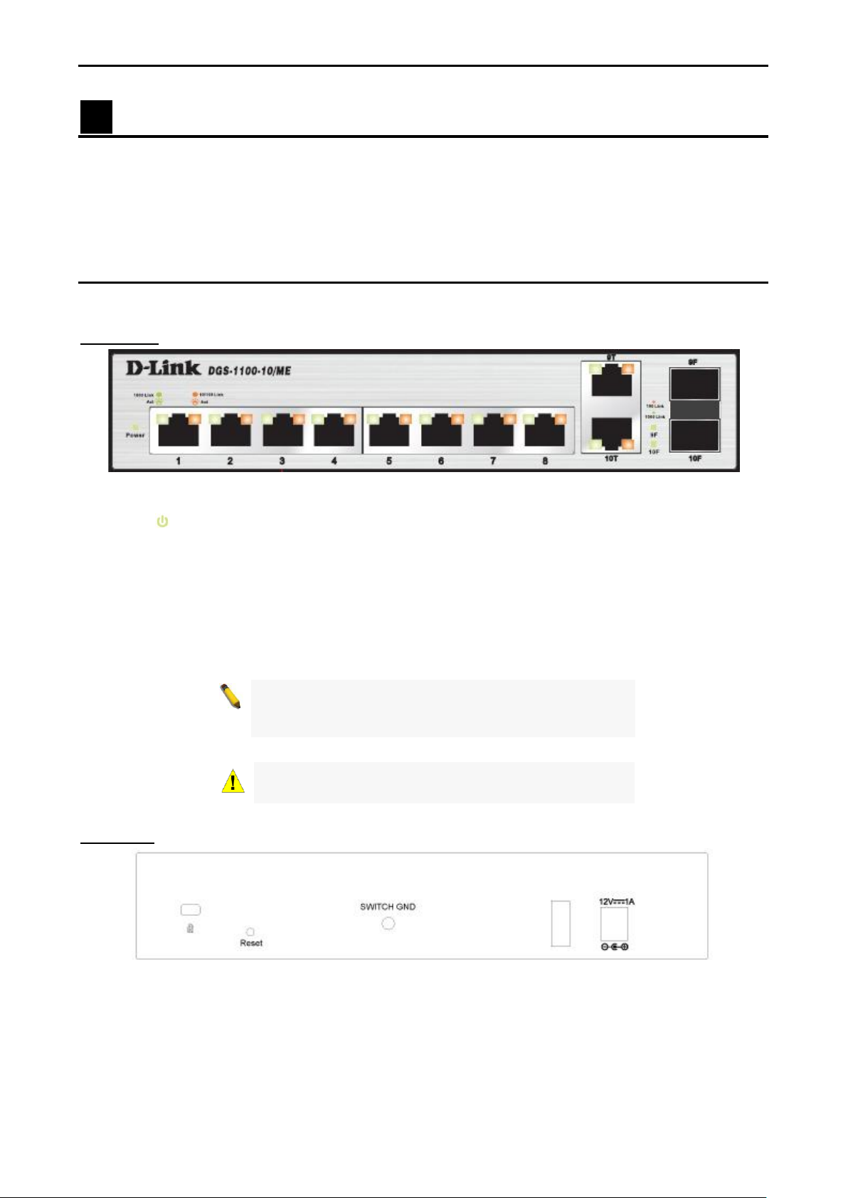
Front Panel
Figure 1.1 – DGS-1100-10/ME Front Panel
Power LED : The Power LED lights up when the Switch is connected to a power source.
Port Link/Act/Speed LED (1-8): A flashing light indicates a network link through the corresponding port.
Blinking indicates that the Switch is either sending or receiving data to the port. When a port has an amber
light, this indicates that the port is running on 10M or 100M. When it has a green light it is running on 1000M.
Port Link/Act/Speed LED (9T, 10T, 9F, 10F): A flashing light indicates a network link through the
corresponding port. Blinking indicates that the Switch is either sending or receiving data to the port. When a
port has amber light indicates that port is running on 10M or 100M and green light indicates that port is
running on 1000M.
Rear Panel
Figure 1.2 – DGS-1100-10/ME Rear Panel
Power: Connect the supplied AC power cable to this port.
Reset: Press and hold the reset button to reset the Switch back to the factory default settings. Note that all
settings will be lost.
33
D-Link DGS-1100-10/ME User Manual
2 Hardware Installation
This chapter provides unpacking and installation information for the D-Link Metro Ethernet Switch.
Step 1: Unpacking
Open the shipping carton and carefully unpack its contents. Please consult the packing list located in the
User Manual to make sure all items are present and undamaged. If any item is missing or damaged, please
contact your local D-Link reseller for replacement.
One D-Link Metro Ethernet Switch
One AC power adapter
Four rubber feet
Screws and two mounting brackets
Wall-mount kit
If any item is found missing or damaged, please contact the local reseller for replacement.
Step 2: Switch Installation
For safe switch installation and operation, it is recommended that you:
Visually inspect the power cord to see that it is secured fully to the AC power connector.
Make sure that there is proper heat dissipation and adequate ventilation around the switch.
Do not place heavy objects on the switch.
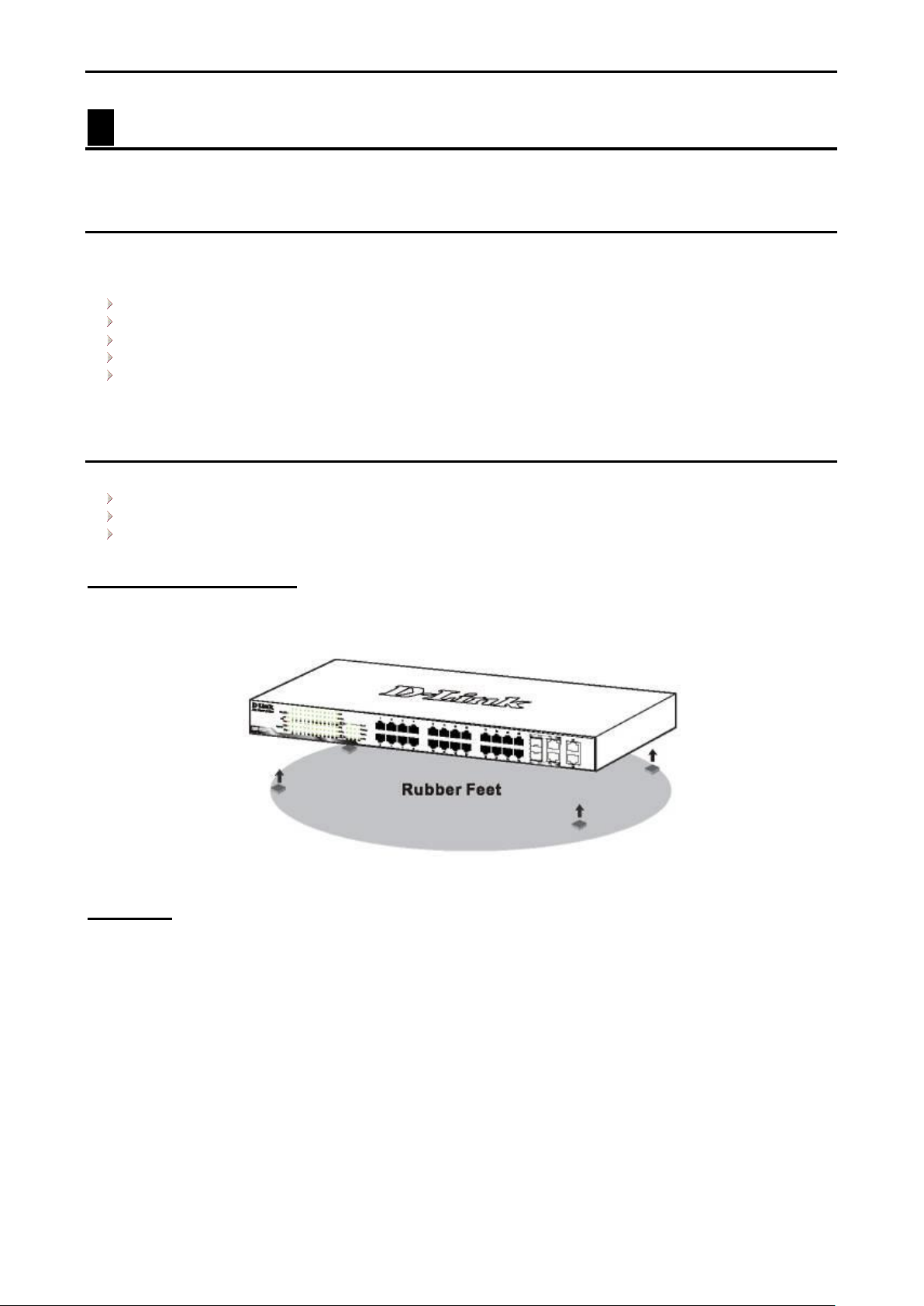
Desktop or Shelf Installation
When installing the switch on a desktop or shelf, the rubber feet included with the device must be attached to
the bottom at each corner of the device’s base. Allow enough ventilation space between the device and the
objects around it.
Figure 2.1 – Attach the adhesive rubber pads to the bottom
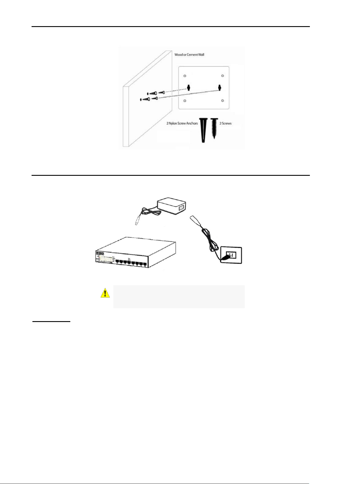
Wall-mount
The Switch can be mounted on a wall. Two mounting slots are provided on the bottom of the switch for this
purpose.
Please follow the installation steps to complete wall-mount process.
Mounting on a cement wall
Step 1: Mount the nylon screw anchors ø5 x 22L mm (included in the accessory kit ) into a cement wall.
Step 2: Drive the T3 x 15L screws into the nylon screw anchors.
Step 3: Hook the mounting holes of the switch back on the screws.
Mounting on a wood wall
Step 1: Drive the T3 x 15L screws into a wood wall.
Step 2. Hook the mounting holes of the switch back on the screws.
44
CAUTION: Do not turn on the power before the
power cables are connected. A power surge may
cause damage to the Switch.
D-Link DGS-1100-10/ME User Manual
Figure 2.2 – Wall mount installation
Step 3 – Plugging in the AC Power Cord
You may now connect the AC power cord into the rear of the switch and to an electrical outlet (preferably
one that is grounded and surge protected).
Figure 2.3 – Plugging the switch into an outlet
Power Failure
As a precaution, the switch should be unplugged in case of power failure. When power is resumed, plug the
switch back in.
66
D-Link DGS-1100-10/ME User Manual
3 Getting Started
This chapter introduces the management interface of D-Link Metro Ethernet Switch.
Management Options
The D-Link Metro Ethernet Switch can be managed through any port on the device by using the Web-based
Management.
Each switch must be assigned its own IP Address, which is used for communication with the Web-Based
Management or a SNMP network manager. The PC should have an IP address in the same range as the
switch. Each switch can allow up to four users to access the Web-Based Management concurrently.
Please refer to the following installation instructions for the Web-based Management.
Using Web-based Management
After a successful physical installation, you can configure the Switch, monitor the network status, and display
statistics using a web browser.
Supported Web Browsers
The embedded Web-based Management currently supports the following web browsers:
Internet Explorer 7 or later version
Mozilla
Firefox 2 or later version
Chrome 5.0 or later version
Safari 4.0 or later version
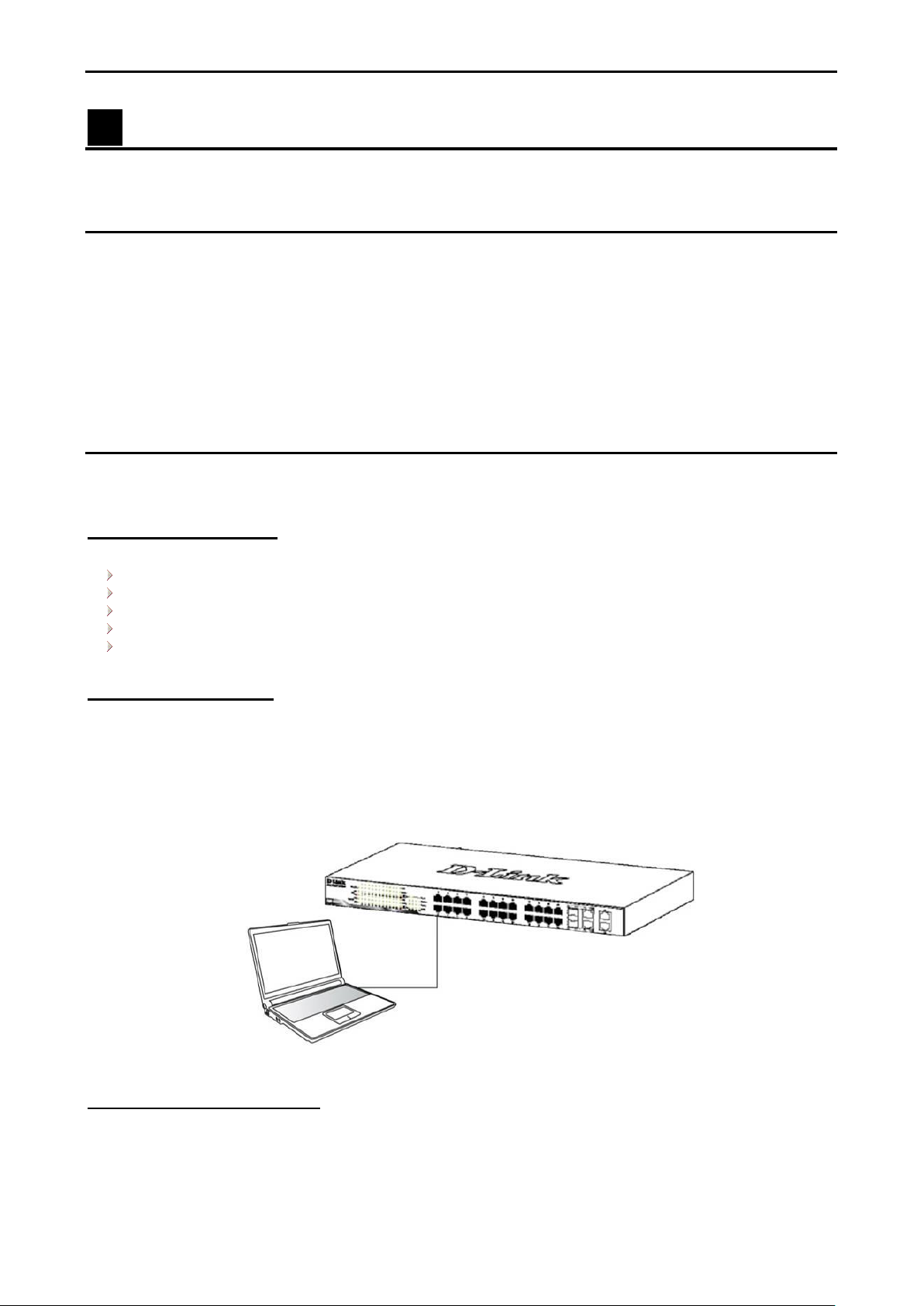
Connecting to the Switch
You will need the following equipment to begin the web configuration of your device:
1. A PC with a RJ-45 Ethernet connection
2. A standard Ethernet cable
Connect the Ethernet cable to any of the ports on the front panel of the switch and to the Ethernet port on the
PC.
Figure 3.1 – Connected Ethernet cable
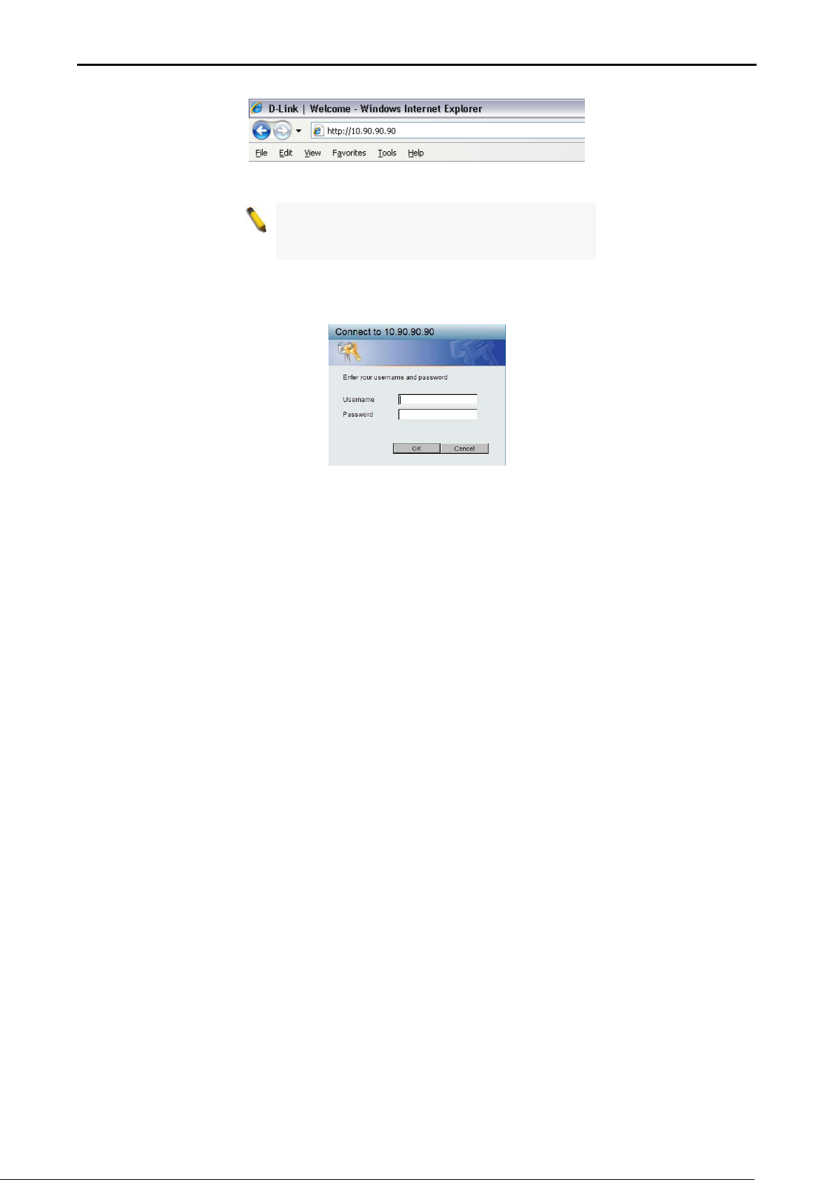
Log in Web-based Management
In order to log in and configure the switch via an Ethernet connection, the PC must have an IP address in the
same subnet as the switch. For example, if the switch has an IP address of 10.90.90.90, the PC should have
an IP address of 10.x.y.z (where x/y is a number between 0 ~ 254 and z is a number between 1 ~ 254), and
a subnet mask of 255.0.0.0. Enter 10.90.90.90 (the factory default IP address) in the address bar of your
web browser and press <Enter>.
77
NOTE: The switch's factory default IP address is
10.90.90.90 with a subnet mask of 255.0.0.0 and
a default gateway of 0.0.0.0.
D-Link DGS-1100-10/ME User Manual
Figure 3.2 –Enter the IP address 10.90.90.90 in the web browser
When the following dialog box appears, enter your user name and password, and click OK.
By default, the Username and Password are empty.
Figure 3.3 – Login Dialog Box
1155
NOTE: If you close the web browser without
clicking the Logout button first, then it will be seen
as an abnormal exit and the login session will still
be occupied.
D-Link DGS-1100-10/ME User Manual
4 Configuration
The features and functions of the D-Link Metro Ethernet Managed Switch can be configured for optimum use
through the Web-based user interface.
Web-based Management
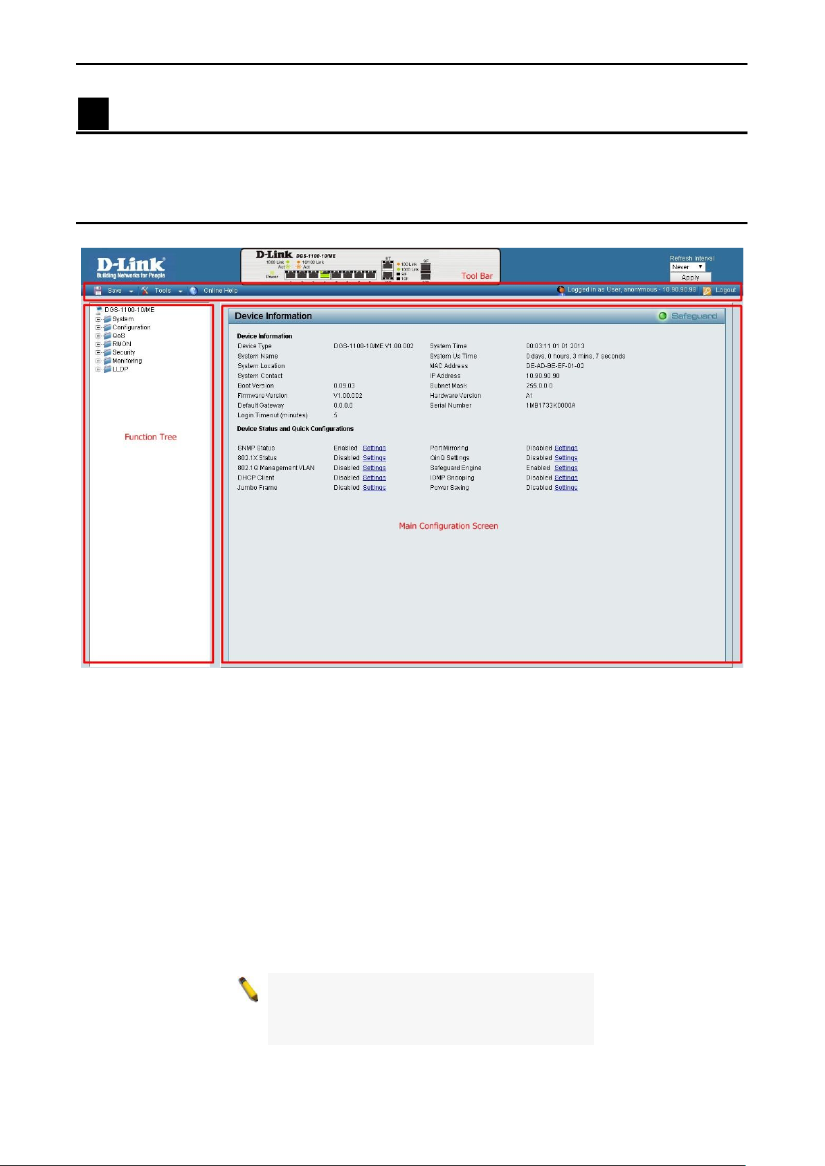
After you log in, you will see the screen below:
Figure 4.1 – Web-based Management
The above image is the Web-based Management home page. The three main areas are the Tool Bar on top,
the Function Tree, and the Main Configuration Panel.
The Tool Bar provides a quick and convenient way for essential utility functions like firmware upgrade and
configuration management.
By choosing different functions in the Function Tree, you can change all the settings in the Main
Configuration Screen. The main configuration screen will show the current status of your Switch by clicking
the model name on top of the function tree.
At the upper right corner of the screen the username and current IP address will be displayed.
Under the username is the Logout button. Click this to end this session.
Click on the D-Link logo at the upper left corner of the screen to be redirected to the local D-Link website.
1166
D-Link DGS-1100-10/ME User Manual
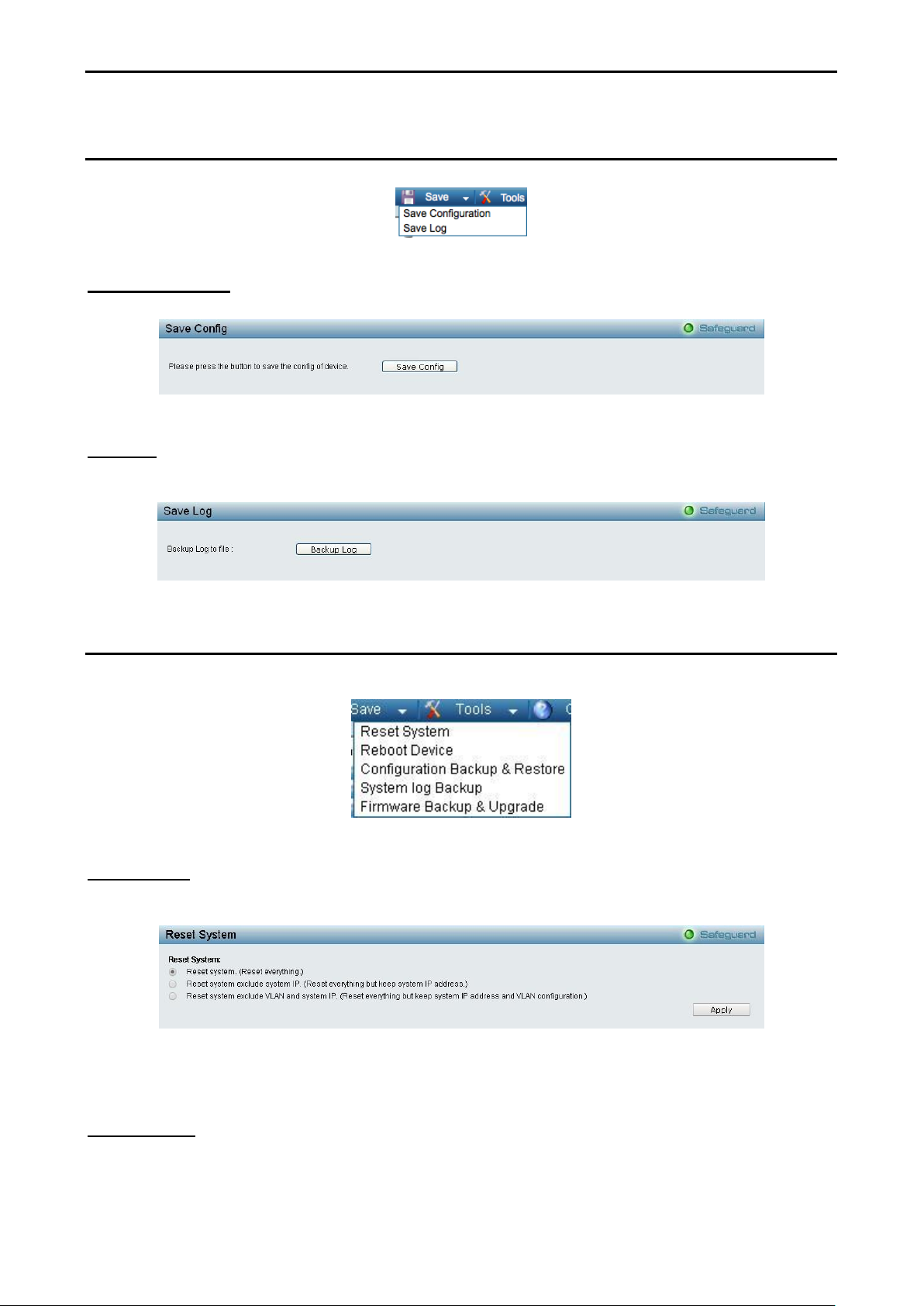
Tool Bar > Save Menu
The Save Menu provides Save Configuration and Save Log functions.
Save Configuration
Select to save the entire configuration changes you have made to the device to switch’s non-volatile RAM.
Save Log
Click Backup Log to save the log entries to your local drive. A pop-up message will prompt you for the file
path. You can view or edit the log file by using a text editor (e.g., Notepad).
Figure 4.2 – Save Menu
Figure 4.3 – Save Configuration
Figure 4.4 – Save Log
Tool Bar > Tool Menu
The Tool Menu offers global function controls such as Reset, Reset System, Reboot Device, Configuration
Backup and Restore, System log Backup, Firmware Backup and Upgrade.
Figure 4.5 – Tool Menu
Reset System
Provides three different reset options for the Switch. All configuration settings in non-volatile RAM will reset
to factory default and the Switch will reboot.
Figure 4.6 – Tool Menu > Reset System
Select a reset method and then click Apply to reset the system.
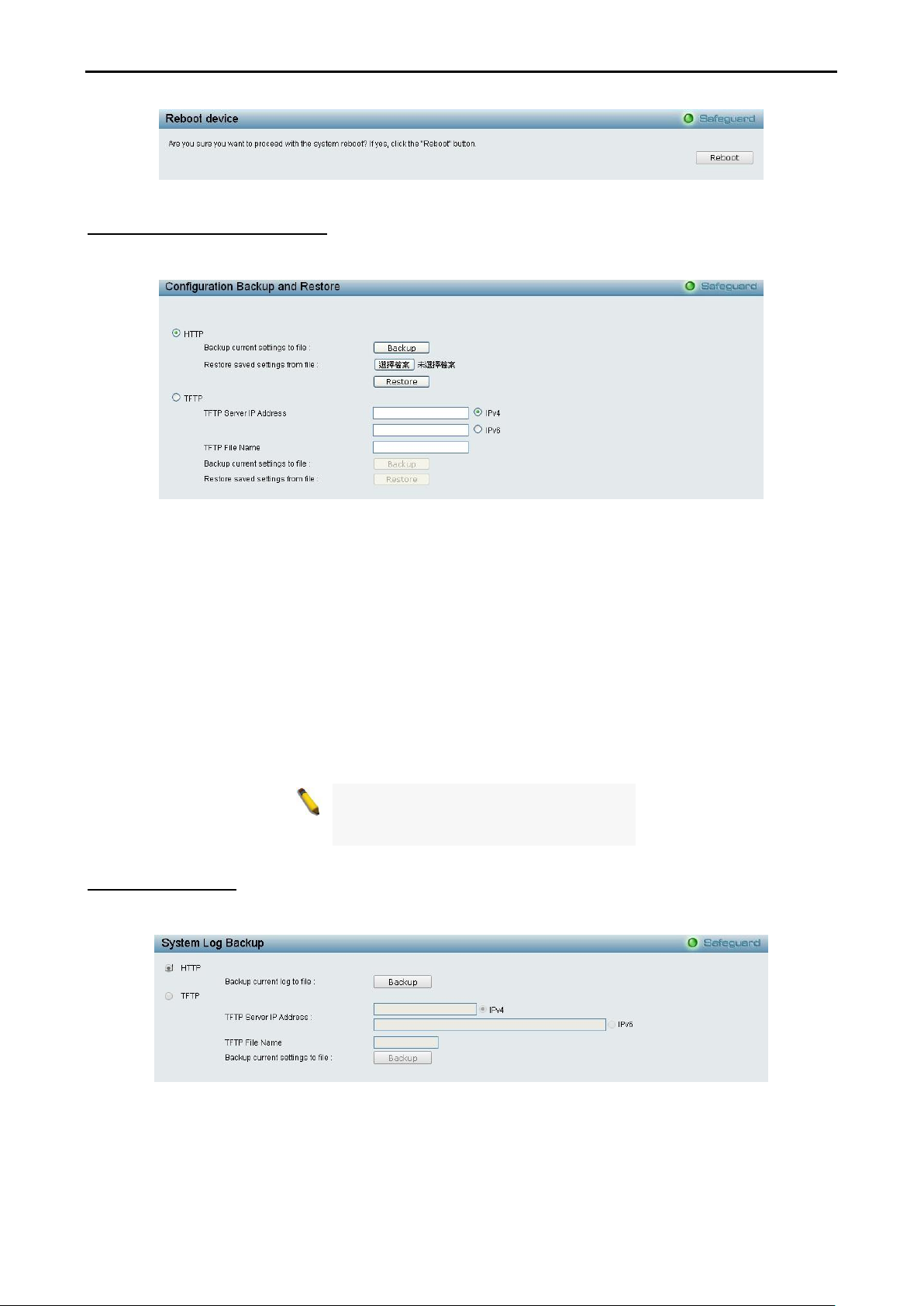
Reboot Device
Click Reboot to restart the switch.
1177
Note: The Switch will reboot after
restoring the saved backup settings are
applied. All current settings will be lost.
D-Link DGS-1100-10/ME User Manual
Figure 4.7 – Tool Menu > Reboot Device
Configuration Backup & Restore
Allow the current configuration settings to be saved to a file (not including the password), and if necessary,
you can restore configuration settings from this file. Two methods can be selected: HTTP or TFTP.
Figure 4.8 – Tool Menu > Configure Backup and Restore
HTTP: Backup or restore the configuration file to or from your local drive.
Click Backup to save the current settings to your disk.
Click Browse to browse your inventory for a saved backup settings file.
Click Restore after selecting the backup settings file you want to restore.
TFTP: TFTP (Trivial File Transfer Protocol) is a file transfer protocol that allows you to transfer files to a
remote TFTP server. Specify TFTP Server IPv4 or IPv6 Address, and TFTP File Name for the configuration
file you want to save to / restore from. The maximum Telnet Server connection is 4.
Click Backup to save the current settings to the TFTP server.
Click Restore after selecting the backup settings file you want to restore.
System Log Backup
Allow the current logs to be saved to a file (not including the password), and if necessary, you can restore
logs from this file. Two methods can be selected: HTTP or TFTP.
HTTP: Click Backup to save the current log to your local drive.
Figure 4.9 – Tool Menu > System Log Backup
1188
CAUTION: Do not disconnect the PC or remove
the power cord from device until the upgrade
completes. The Switch may crash if the firmware
upgrade is incomplete.
D-Link DGS-1100-10/ME User Manual
TFTP: TFTP (Trivial File Transfer Protocol) is a file transfer protocol that allows you to transfer files to a
remote TFTP server. Specify TFTP Server IPv4 or IPv6 Address, and TFTP File Name for the configuration
file you want to save to / restore from.
Click Backup to save the current log to the TFTP server.
Click Restore after selecting the backup log file you want to restore.
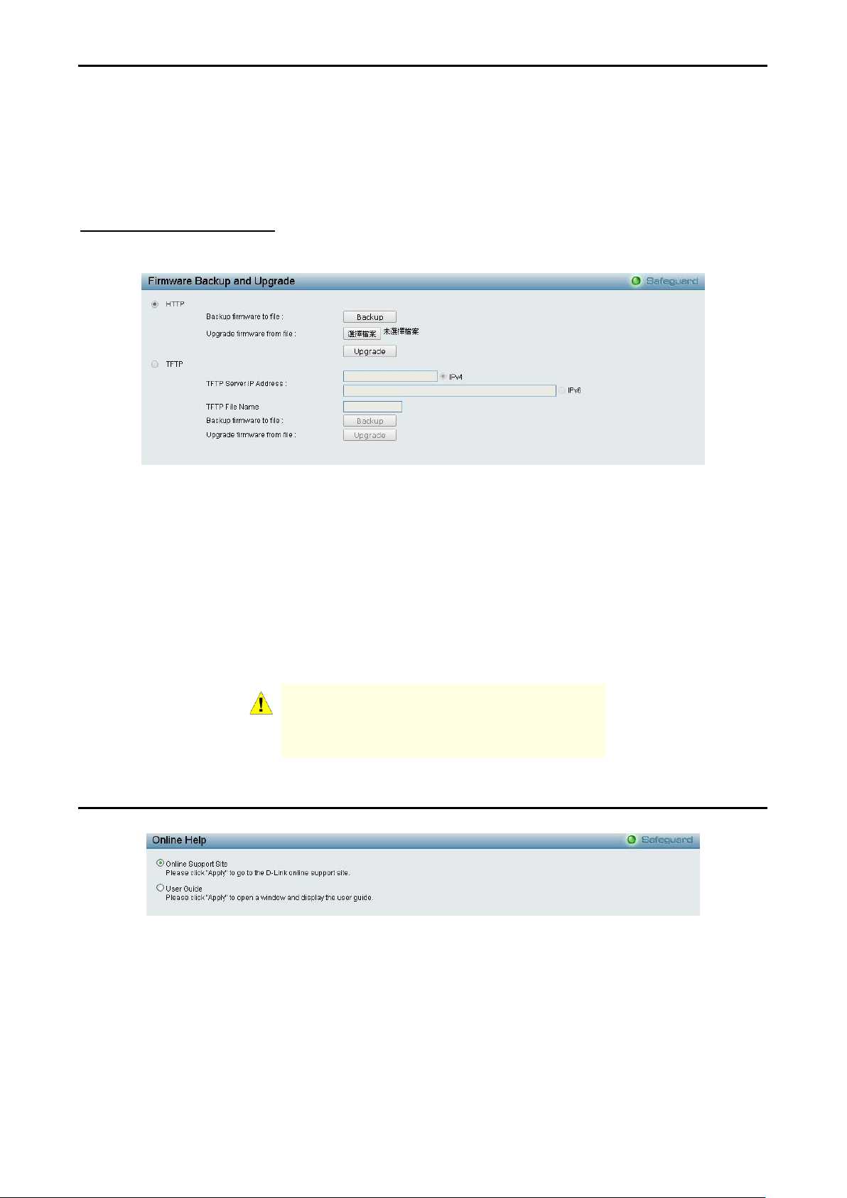
Firmware Backup & Upgrade
Allow for the firmware to be saved, or for an existing firmware file to be uploaded to the Switch. Two methods
can be selected: HTTP or TFTP.
Figure 4.10 – Tool Menu > Firmware Backup and Upgrade
HTTP: Backup or upgrade the firmware to or from your local PC drive.
Click Backup to save the firmware to your disk.
Click Browse to browse your inventory for a saved firmware file.
Click Upgrade after selecting the firmware file you want to use.
TFTP: Backup or upgrade the firmware to or from a remote TFTP server. Specify TFTP Server IPv4 or IPv6
Address and File Name for the configuration file you want to save to / restore from. The maximum Telnet
Server connection is 4.
Click Backup to save the firmware to the TFTP server.
Click Upgrade after selecting the firmware file you want to restore.
Tool Bar > Online Help
The Online Help provides two ways of online support:
D-Link Support Site: This will re-direct you to the D-Link website where you can find online resources such
as updated firmware images.
User Guide: This can offer an immediate reference for the feature definition or configuration guide.
Figure 4.11 – Online Help
1199
D-Link DGS-1100-10/ME User Manual
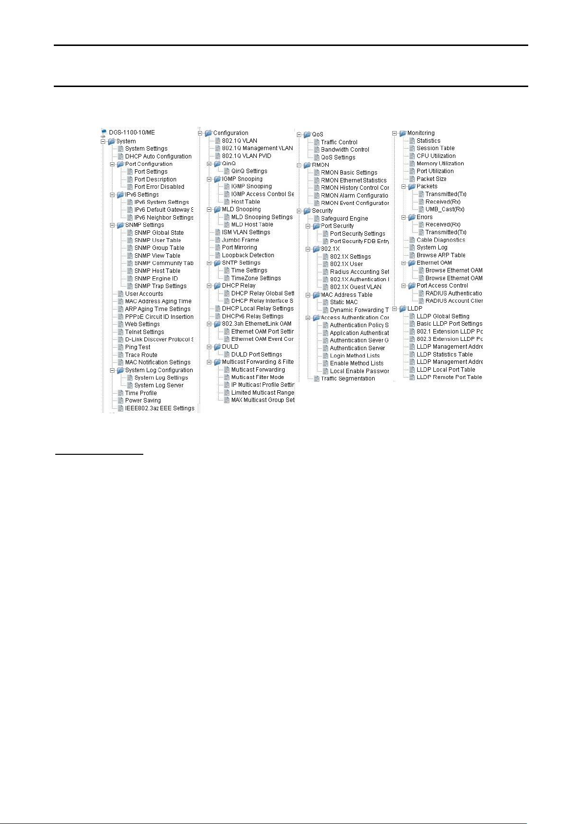
Function Tree
All configuration options on the switch are accessed through the Setup menu on the left side of the screen.
Click on the setup item that you want to configure. The following sections provide more detailed description
of each feature and function.
Figure 4.12 –Function Tree
Device Information
The Device Information provides an overview of the switch, including essential information such as firmware
& hardware information, and IP address.
It also offers an overall status of common software features:
SNMP Status: Click Settings to link to System > SNMP Settings > SNMP Global State. Default is enabled.
802.1X Status: Click Settings to link to Security > 802.1X > 802.1X Settings. Default is disabled.
802.1Q Management VLAN: Click Settings to link to Configuration > 802.1Q Management VLAN. Default is
disabled.
DHCP Client: Click Settings to link to System > System Settings. Default is disabled.
Jumbo Frame: Click Settings to link to Configuration > Jumbo Frame. Default is disabled.
Port Mirroring: Click Settings to link to Configuration > Port Mirroring. Default is disabled.
QinQ Settings: Click Settings to link to Configuration > QinQ > QinQ Settings. Default is disabled.
Safeguard Engine: Click Settings to link to Security > Safeguard Engine. Default is enabled.
IGMP Snooping: Click Settings to link to Configuration > IGMP Snooping > IGMP Snooping. Default is
disabled.
Power Saving: Click Settings to link to System > Power Saving. Default is disabled.
2200
D-Link DGS-1100-10/ME User Manual
Figure4.13 – Device Information
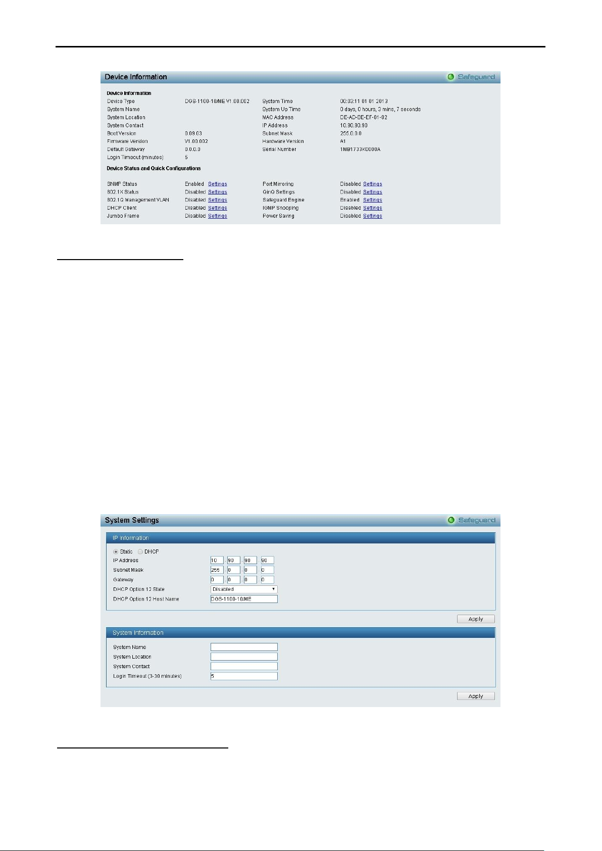
System > System Settings
The System Setting allows you to configure the IP address and the basic system information of the Switch.
IP Information: There are two ways for the switch to obtain an IP address: Static and DHCP (Dynamic Host
Configuration Protocol).
When using static mode, the IP Address, Subnet Mask, Gateway and DHCP Option 12 State can be
manually configured. When using DHCP mode, the Switch will first look for a DHCP server to provide it with
an IP address (including network mask and default gateway) before using the default or previously entered
settings. By default the IP setting is static mode with an IP address of 10.90.90.90 and subnet mask of
255.0.0.0.
System Information: By entering a System Name and System Location, the device can more easily be
recognized.
System Contact: By entering a system contact.
Login Timeout (3-30 minutes): The Login Timeout controls the idle time-out period for security purposes,
and when there is no action for a specific time span in the Web-based Management. If the current session
times out (expires), the user is required a re-login before using the Web-based Management again. Selective
range is from 3 to 30 minutes, and the default setting is 5 minutes.
Figure 4.14 – System > System Settings
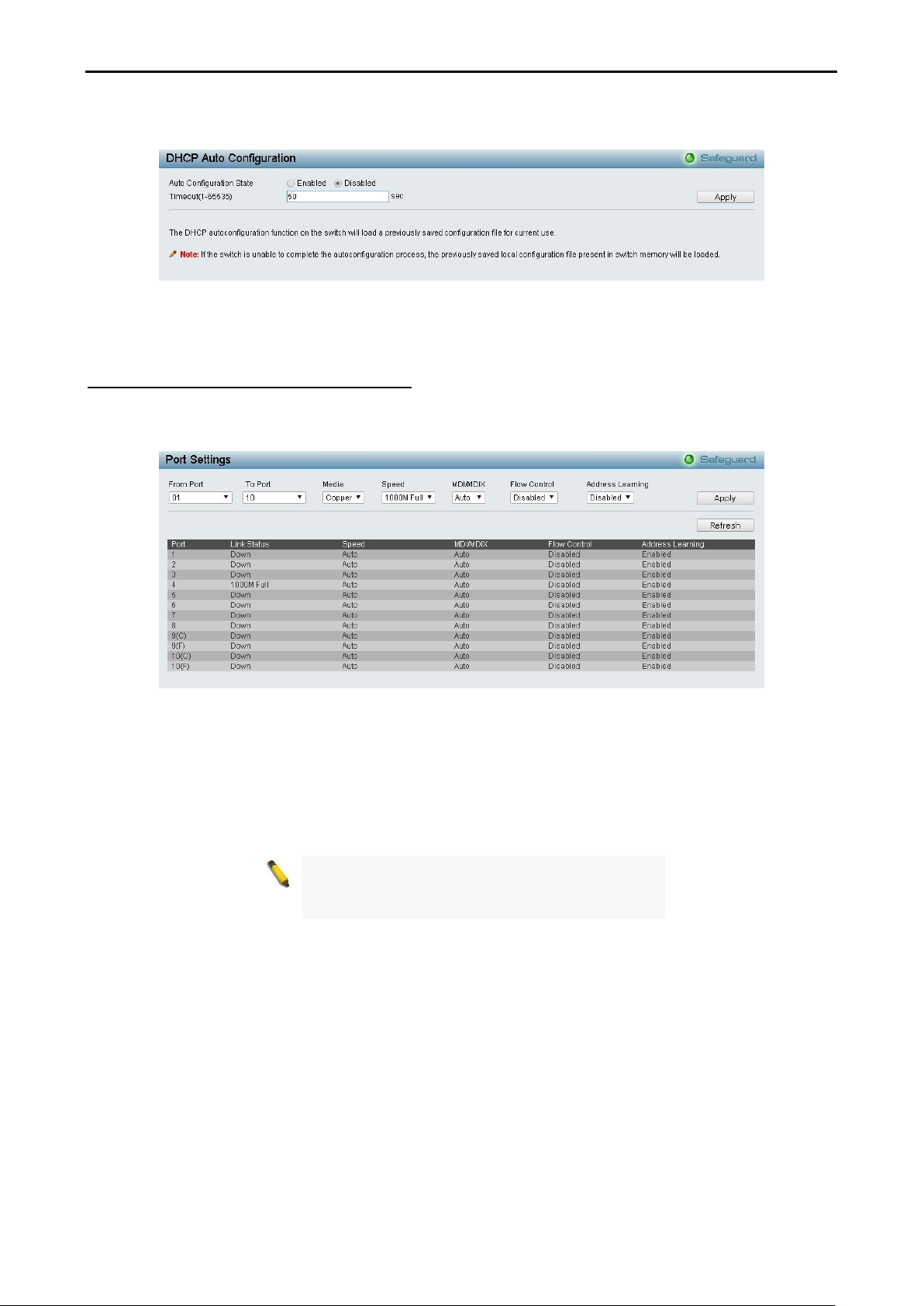
System > DHCP Auto Configuration
From this page you can enable the DHCP Auto Configuration feature on the Switch. When enabled, the
Switch becomes a DHCP client and gets the configuration file from a TFTP server automatically on next boot
up. To accomplish this, the DHCP server must deliver the TFTP server IP address and configuration file
2211
NOTE: Be sure to adjust port speed settings
appropriately after changing the connected cable
media types.
D-Link DGS-1100-10/ME User Manual
name information in the DHCP reply packet. The TFTP server must be up and running and store the
necessary configuration file in its base directory when the request is received from the Switch.
Figure 4.15 – System > DHCP Auto Configuration
Timeout (1-65535): Specify the timeout.
System > Port Configuration > Port Settings
In the Port Setting page, the status of all ports can be monitored and adjusted for optimum configuration. By
selecting a range of ports (From Port and To Port), the Speed can be set for all selected ports by clicking
Apply. Press the Refresh button to view the latest information.
Figure 4.16 – System > Port Configuration > Port Settings
Media: Specify the media type of the port.
Speed: Gigabit Fiber connections can operate in 1000M Full Force Mode, Auto Mode or Disabled. Copper
connections can operate in Forced Mode settings (1000M Full, 100M Full, 100M Half, 10M Full, 10M Half),
Auto, or Disabled. 100M Fiber connections support 100M Full Force Mode, 100M Half Force Mode, or
Disabled. The default setting for all ports is Auto.
MDI/MDIX:
A medium dependent interface (MDI) port is an Ethernet port connection typically used on a Network
Interface Card (NIC) or Integrated NIC port on a PC. Switches and hubs usually use Medium dependent
interface crossover (MDIX) interface. When connecting the Switch to end stations, you have to use straight
through Ethernet cables to make sure the Tx/Rx pairs match up properly. When connecting the Switch to
other networking devices, a crossover cable must be used.
This switch provides a configurable MDI/MDIX function for users. The switches can be set as an MDI port in
order to connect to other hubs or switches without an Ethernet crossover cable.
Auto is designed on the switch to detect if the connection is backwards, and automatically chooses MDI or
MDIX to properly match the connection. The default setting is “Auto” MDI/MDIX.
Flow Control: Enable this function to mitigate traffic congestion. Ports configured for full-duplex use 802.3x
flow control and half-duplex ports use backpressure flow control. The default setting is Disabled.
2222
D-Link DGS-1100-10/ME User Manual
Address Learning: Enable or disable the address learning function. The default setting is Enabled.
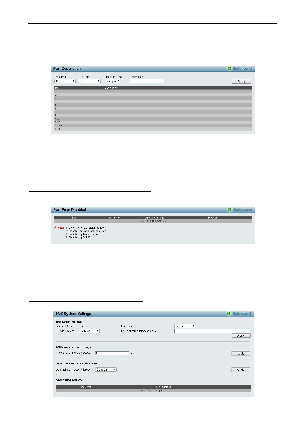
System > Port Configuration > Port Description
In the Port Description page, you may name various ports on the Switch.
Figure 4.17 – System > Port Configuration > Port Description
From Port / To Port: Specify the range of ports to describe.
Medium Type: Specify the media type of the port
Description: Specify the description of ports.
Click Apply to set the description in the table.
System > Port Configuration > Port Error Disabled
The Port Error Disabled page displays the information about ports that have had their connection status
disabled, for reasons such as link down status.
Figure 5.21 – System > Port Configuration > Port Error Disabled
Port: Displays the port that has been error disabled.
Port State: Describes the current running state of the port, whether Enabled or Disabled.
Connection Status: This field will read the uplink status of the individual ports, whether Enabled or Disabled.
Reason: Describes the reason why the port has been error-disabled.
System > IPv6 Settings > IPv6 System Settings
From this page you can configure IPv6 system information.
.
2233
D-Link DGS-1100-10/ME User Manual
Figure 4.18 – System > IPv6 Settings > IPv6 System Settings
IPv6 System Settings:
Interface Name: Displays the IPv6 interface name.
IPv6 State: Select to either enable or disable IPv6.
DHCPv6 Client: Select to either enable or disable the switch as an IPv6 client.
IPv6 Network Address: Specifies the IPv6 Network Address.
NS Retransmit Time Settings:
NS Retransmit Time (1-3600): Enter the Neighbor Solicitation’s retransmit timer in seconds. The field range
is 1-3600, and default is 1 second.
Automatic Link Local State Settings:
Automatic Link Local Address: Select either Enabled or Disabled.
Click Apply for the settings to take effect.
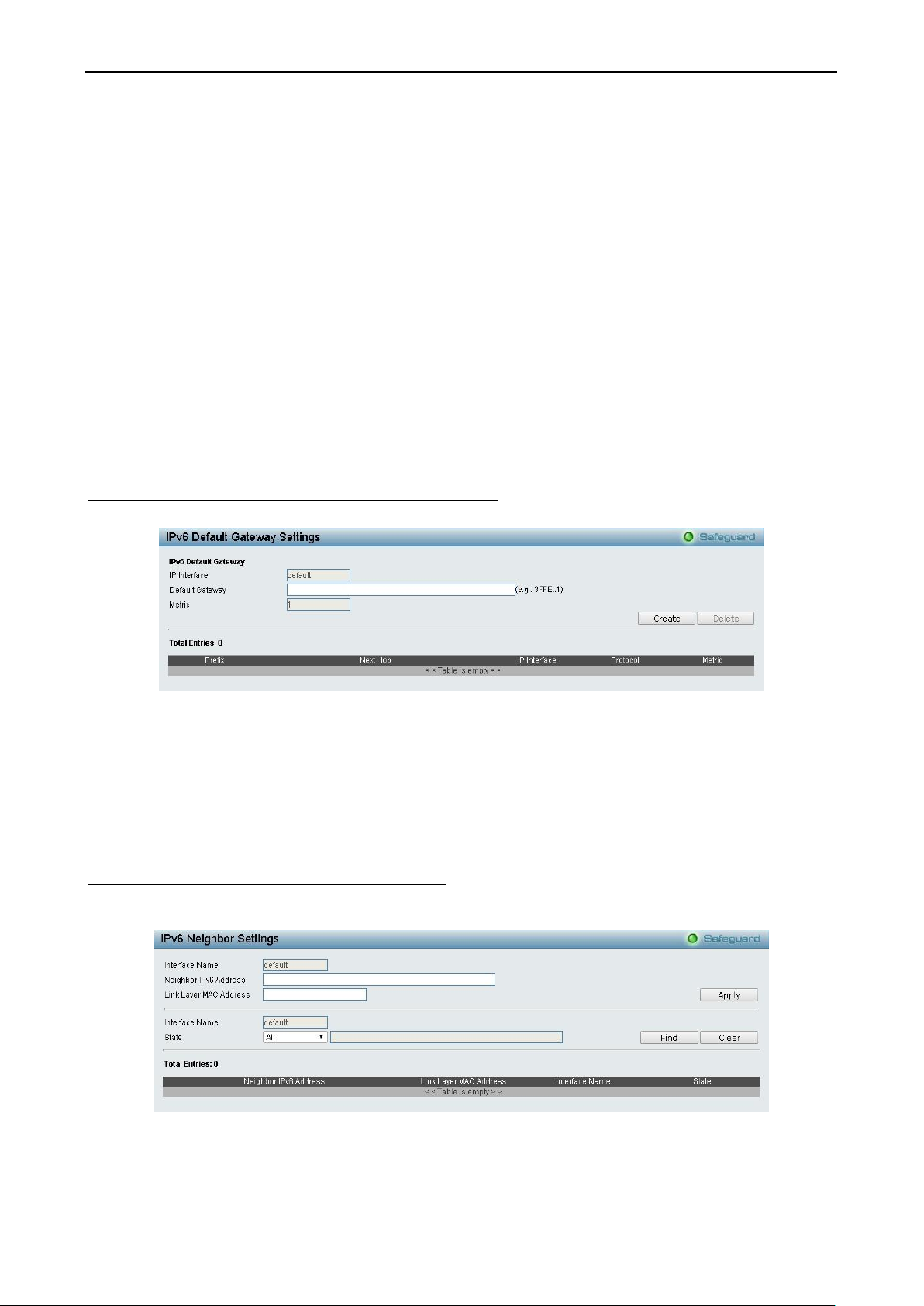
System > IPv6 Settings > IPv6 Default Gateway Settings
From this page you can configure the IPv6 gateway settings.
Figure 4.19 – System > IPv6 Settings > IPv6 Route Settings
IP Interface: Specify the IP interface which to be created.
Default Gateway: The corresponding IPv6 address for the next hop Gateway address in IPv6 format.
Metric: Represents the metric value of the IP interface entered into the table. This field may read a number
between 1 and 65535.
Click Create to accept the changes made or and click the Delete button to remove the entry.
System > IPv6 Settings > IPv6 Neighbor Settings
You can configure the Switch’s IPv6 neighbor settings. The Switch’s current IPv6 neighbor settings will be
displayed in the table at the bottom of this window.
Figure 4.20 – System > IPv6 Settings > IPv6 Neighbor Settings
Interface Name: Enter the interface name of the IPv6 neighbor.
Neighbor IPv6 Address: Enter the neighbor IPv6 address.
2244
D-Link DGS-1100-10/ME User Manual
Link Layer MAC Address: Enter the link layer MAC address.
Click Apply for the settings to take effect.
Interface Name: Specifies the interface name of the IPv6 neighbor. To search for all the current interfaces
on the Switch, go to the second Interface Name field in the middle part of the window, tick the All check box.
Tick the Hardware option to display all the neighbor cache entries which were written into the hardware table.
State: Use the drop-down menu to select All, Address, Static or Dynamic. When the user selects address
from the drop-down menu, you will be able to enter an IP address in the space provided next to the state
option.
Click Find to locate a specific entry based on the information entered.
Click Clear to clear all the information entered in the fields.
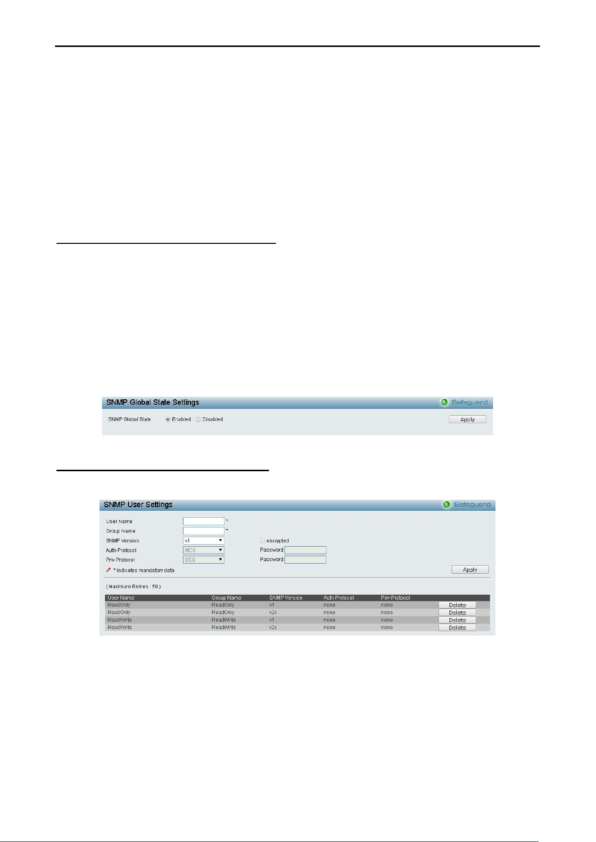
System > SNMP Settings > SNMP Global State
Simple Network Management Protocol (SNMP) is an OSI Layer 7 (Application Layer) protocol designed
specifically for managing and monitoring network devices. SNMP enables network management stations to
read and modify the settings of gateways, routers, switches, and other network devices. Use SNMP to
configure system features for proper operation, monitor performance and detect potential problems in the
Switch or LAN.
Managed devices that support SNMP include software (referred to as an agent) that runs locally on the
device. A defined set of variables (managed objects) is maintained by the SNMP agent and used to manage
the device. These objects are defined in a Management Information Base (MIB), which provides a standard
presentation of the information controlled by the on-board SNMP agent. SNMP defines both the format of the
MIB specifications and the protocol used to access this information over the network.
The default SNMP global state is disabled. Select Enable and click Apply to enable the SNMP function.
Figure 4.21 – System > SNMP Settings > SNMP Global State
System > SNMP Settings > SNMP User Table
This page is used to maintain the SNMP user table for the use of SNMPv3. SNMPv3 allows or restricts users
using the MIB OID, and also encrypts the SNMP messages sent out between users and Switch.
Figure 4.22 – System > SNMP Settings > SNMP User Table
User Name: Enter a SNMP user name of up to 32 characters.
Group Name: Enter the SNMP group of the SNMP user.
SNMP Version: Select the SNMP version of the user. Only SNMPv3 encrypts the messages.
Encrypt: If you selected SNMP v3, tick the box to enable encryption.
Auth-Protocol/Password: Specify either HMAC-MD5-96 or HMAC-SHA to be the authentication protocol.
Enter a password for SNMPv3 encryption in the right column.
Priv-Protocol/Password: Select either no authorization or DES 56-bit encryption and then enter a
password for SNMPv3 encryption in the right column.
2255
D-Link DGS-1100-10/ME User Manual
Click Apply to create a new SNMP user account or click Delete to remove any existing data.
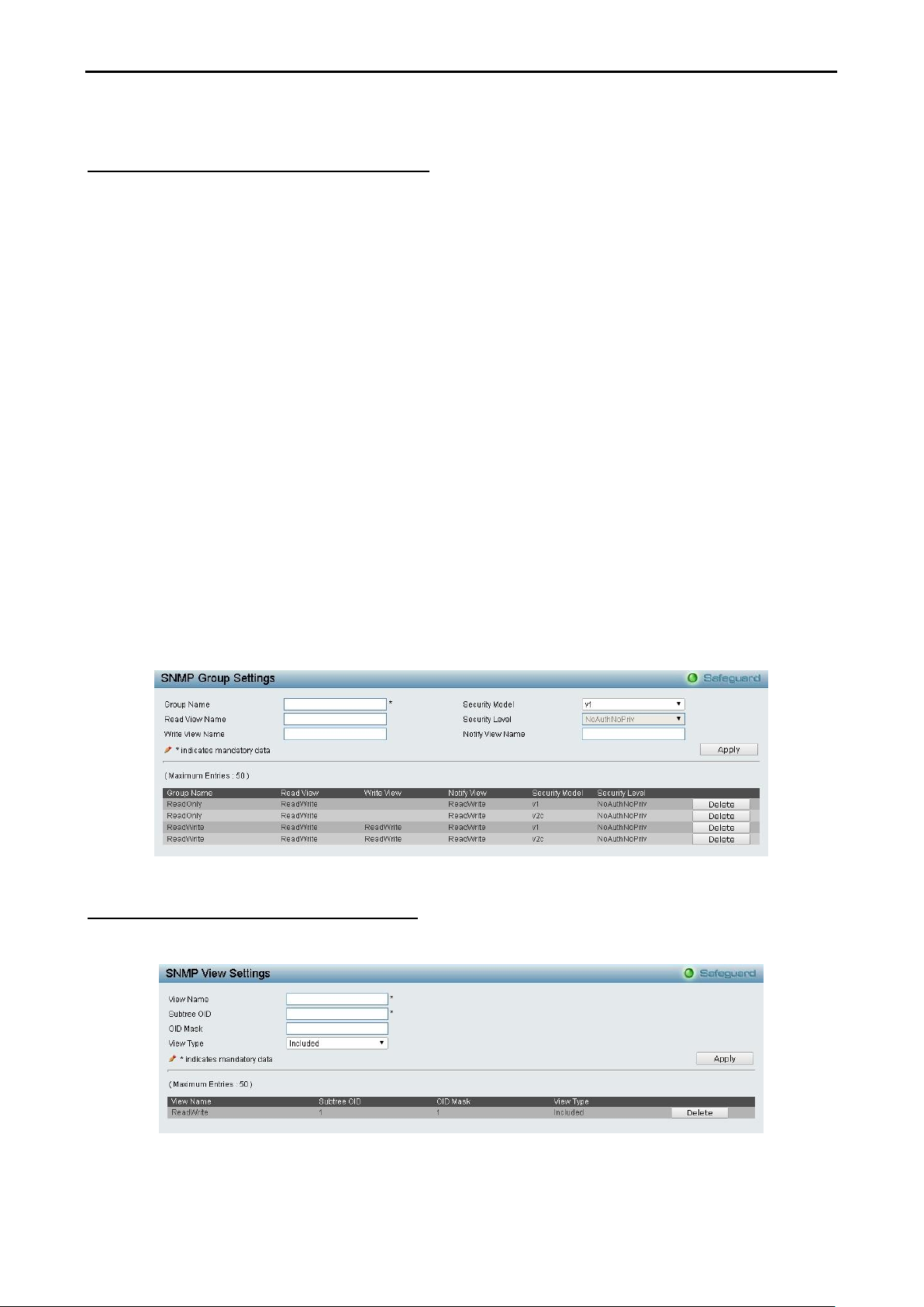
System > SNMP Settings > SNMP Group Table
This page is used to maintain the SNMP Group Table associating to the users in SNMP User Table.
SNMPv3 can control MIB access and security policies for a user group directly.
Group Name: Enter a SNMP user group name of up to 32 characters.
Read View Name: Enter a SNMP group name for users that are allowed SNMP read privileges to the
Switch's SNMP agent.
Write View Name: Enter a SNMP group name for users that are allowed SNMP write privileges to the
Switch's SNMP agent.
Security Model: Select the SNMP security model.
SNMPv1 - SNMPv1 does not support the security features.
SNMPv2 - SNMPv2 supports both centralized and distributed network management strategies. It
includes improvements in the Structure of Management Information (SMI) and adds some security
features.
SNMPv3 - SNMPv3 provides secure access to devices through a combination of authentication and
encrypting packets over the network.
Security Level: This function is only available when you select SNMPv3 security level.
NoAuthNoPriv - No authorization and no encryption for packets sent between the Switch and SNMP
manager.
AuthNoPriv - Authorization is required, but no encryption for packets sent between the Switch and
SNMP manager.
AuthPriv – Both authorization and encryption are required for packets sent between the Switch and
SNMP manger.
Notify View Name: Enter a SNMP group name for users that can receive SNMP trap messages generated
by the Switch's SNMP agent.
Figure 4.23– System > SNMP Settings > SNMP Group Table
System > SNMP Settings > SNMP View Table
From this page you can maintain SNMP views to community strings that define the MIB objects which can be
accessed by a remote SNMP manager.
Figure 4.24 – System > SNMP Settings > SNMP View Table
View Name: Enter a view name of up to 32 characters.
2266
D-Link DGS-1100-10/ME User Manual
Subtree OID: The Object Identifier (OID) Subtree for the view. The OID identifies an object tree (MIB tree)
that will be included or excluded from access by an SNMP manager.
OID Mask: The mask of the Subtree OID. 1 means this object number is concerned, 0 means do not
concerned. For example 1.3.6.1.2.1.1 with mask 1.1.1.1.1.1.0 means 1.3.6.1.2.1.X.
View Type: Specify the configured OID is Included or Excluded that a SNMP manager can access.
Click Apply to create a new view or click Delete to remove an existing view.
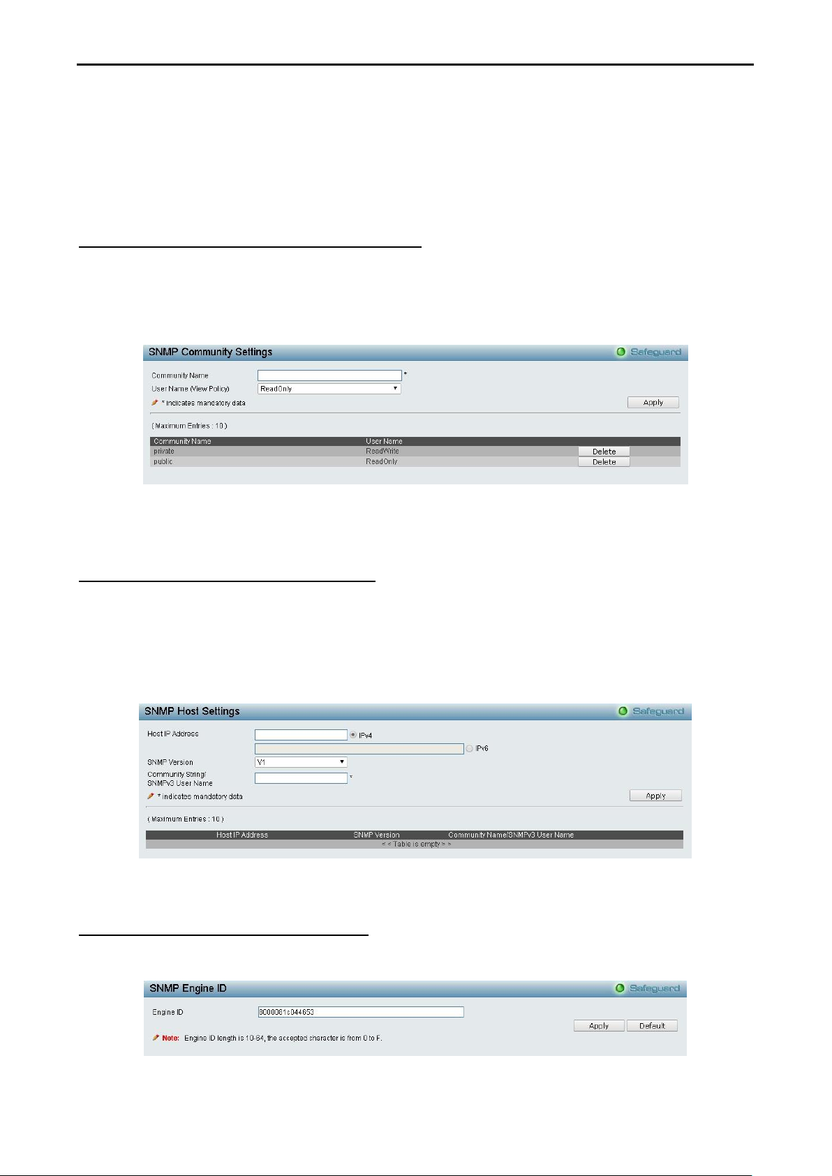
System > SNMP Settings > SNMP Community Table
This page is used to maintain the SNMP community string of the SNMP managers using the same
community string are permitted to gain access to the Switch's SNMP agent.
Community Name: Enter a name of the community string.
User Name (View Policy): Select the read/write or read-only level permission for the MIB objects accessible
to the SNMP community.
Figure 4.25 – System > SNMP Settings > SNMP Community Table
Click Apply to create a new SNMP community or click Delete to remove an existing community.
System > SNMP Settings > SNMP Host Table
This page is to configure the SNMP trap recipients.
Host IP Address: Select IPv4 or IPv6 and specify the IP address of SNMP management host.
SNMP Version: Specify the SNMP version to be used to the management host.
Community String/SNMPv3 User Name: Specify the community string or SNMPv3 user name for the
management host.
Figure 4.26 – System > SNMP Settings > SNMP Host Table
Click Apply to create a new SNMP host or click Delete to remove an existing host.
System > SNMP Settings > SNMP Engine ID
The Engine ID is a unique identifier used to identify the SNMPv3 engine on the Switch.
Input the Engine ID then click Apply to apply the changes or click Delete to reset back to the default value.
Figure 4.27 – System > SNMP Settings > SNMP Engine ID
2277
D-Link DGS-1100-10/ME User Manual
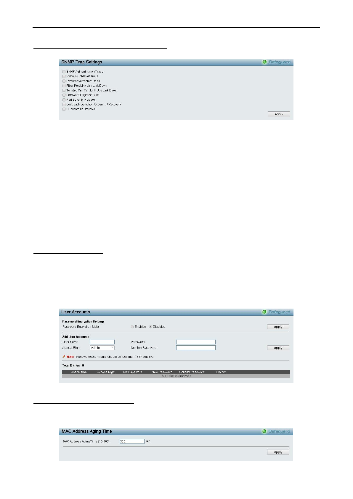
System > SNMP Settings > SNMP Trap Settings
From this page you can specify whether the device can send SNMP notifications.
Figure 4.28 – System > SNMP Settings > SNMP Trap Settings
SNMP Authentication Traps: Tick the box to send authentication failure notifications.
System Coldstart Traps: System cold start boot-up information.
System Warmstart Traps: System warm start boot-up information.
Fiber Port Link Up / Link Down: Fiber port connection information.
Twisted Pair Port Link Up / Link Down: Twisted pair port connection information.
Firmware Upgrade State: Information of firmware upgrade - success or failure.
Port Security Violation: Information of Port Security Violation.
Loopback Detection occurring / recovery: Tick the box to send SNMP Trap when Loopback Detection
occurring and recovery.
Duplicate IP Detected: Information of duplicate IP was detected.
Click Apply for the changes to take effect.
System > User Accounts
From this page you can control user privileges. Select Enabled or Disable to configure the Password
Encryption State. Add a new user by typing in a User Name, Password and choose the level of
privilege(Admin, Operator or User) from the Access Right drop-down menu, then click the Apply button.
You can modify an existing user account in the User Account Table. To change the password, type in the
Old Password, New Password and retype it in the Confirm New Password entry field and select the
Encrypt, then click the Edit button. To delete the user account, click the Delete button.
Figure 4.29– System > User Accounts
System > MAC Address Aging Time
The MAC Address Aging Time page specifies the length of time a learned MAC Address will remain in the
forwarding table without being accessed (that is, how long a learned MAC address is allowed to remain idle).
To change this, type in a different value representing the MAC address age-out time in seconds.
2288
D-Link DGS-1100-10/ME User Manual
Figure 4.30 – System > MAC Address Aging Time
MAC Address Aging Time (10-600): Specifies the aging time of MAC address on the Switch. The range is
from 10 to 600, and the default is 300 seconds.
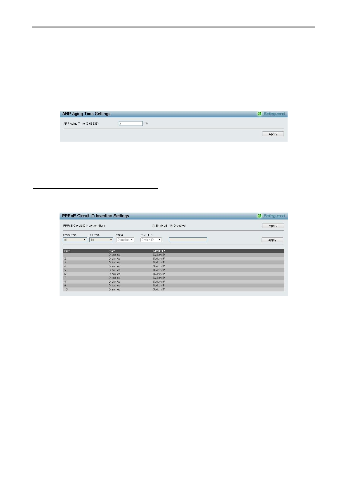
System > ARP Aging Time Settings
The ARP Aging Time Settings page provides user to globally set the maximum amount of time, in minutes,
and Address Resolution Protocol (ARP) entry can remain in the Switch’s ARP table, without being accessed,
before it is dropped from the table.
Figure 4.31 – System > ARP Aging Time Settings
ARP Aging Time (0-65535): Enter the ARP aging time on the Switch. The range is from 0 to 65535 with a
default setting of 3 minutes.
System > PPPoE Circuit ID Insertion Settings
The PPPoE Circuit ID Insertion Settings page specifies the configuration of settings. When enabled, the
system will insert the circuit tag to the received PPPoE discover request and the request packet if the tag is
absent. It will remove the circuit ID tag from the received PPPoE offer and session confirmation packet.
Figure 4.32 – System > PPPoE Circuit ID Insertion Settings
PPPoE Circuit Insertion State: Enable or disable the PPPoE circuit insertion state, and click Apply to take
effect.
From Port/ To Port: Specifies the ports to be configured.
State: Enable or disable the state of specified ports.
Circuit ID: Specifies the Circuit ID is Switch IP, Switch MAC or UDF String.
Switch IP – The Switch’s IP address will be used to encode the circuit ID option. This is the default.
Switch MAC – The MAC address of the Switch will be used to encode the circuit ID option.
UDF String – A user specified string to be used to encode the circuit ID option. Enter a string with
the maximum length of 32.
Click Apply for the changes to take effect.
System > Web Settings
The Web State is Enabled by default. If you select Disabled, you will lose the ability to configure the system
through the web interface as soon as these settings are applied.
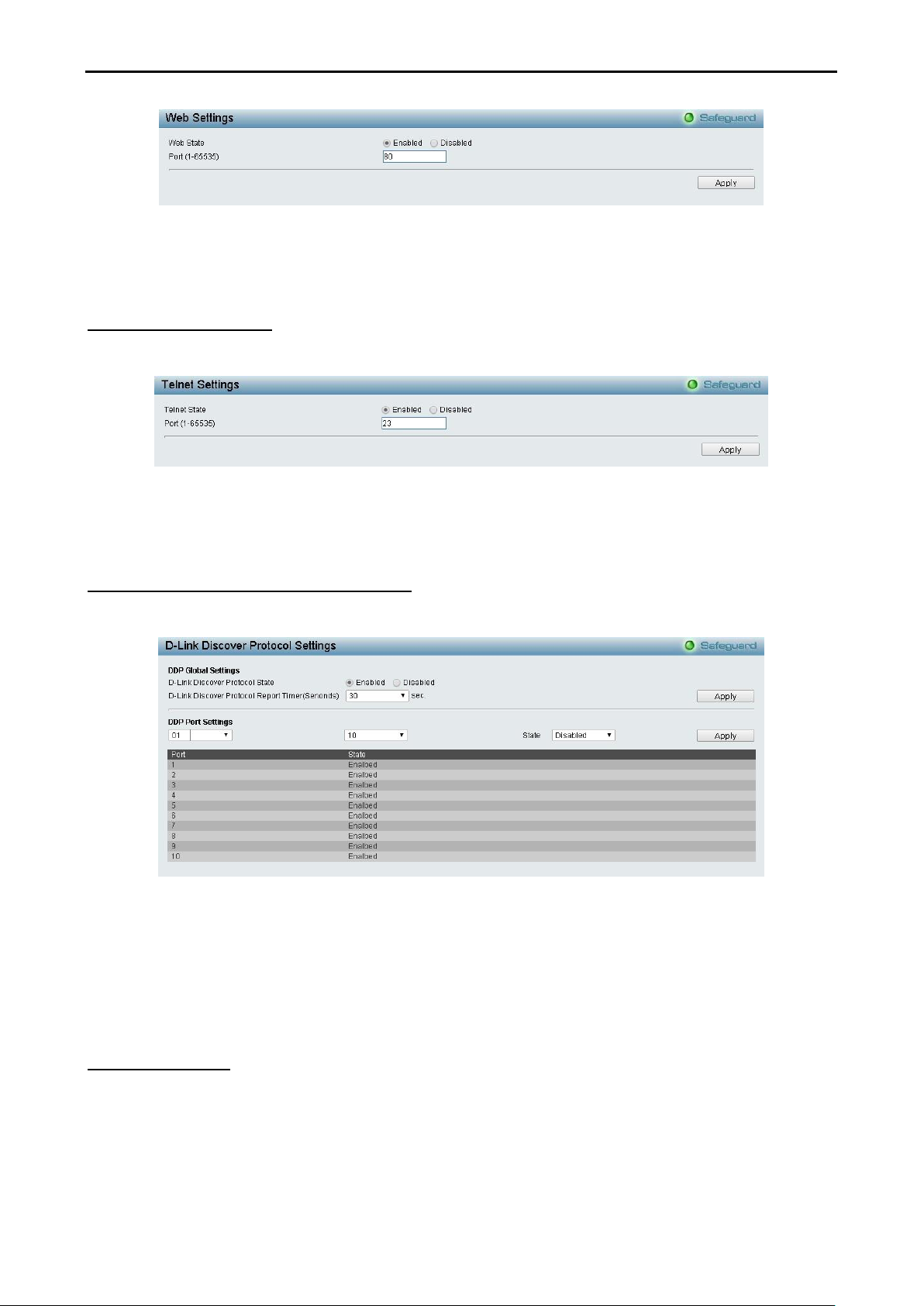
2299
D-Link DGS-1100-10/ME User Manual
Figure 4.33– System > Web Settings
Port (1-65535): Specifies the Port number. The range is between 1 and 65535 with the well-known default is
80.
System > Telnet Settings
Telnet configuration is Enabled by default. If you do not want to allow Telnet configuration, then select
Disabled.
Figure 4.34 – System > Telnet Settings
Port (1-65535): The TCP port number. TCP ports are numbered between 1 and 65535. The well-known TCP
port for the Telnet protocol is 23.
System > D-Link Discover Protocol Settings
For the D-Link Discovery Protocol (DDP) supported device, this page is an option for you to disable DDP or
configure the DDP packet report timer.
Figure 4.35 – System > D-Link Discover Protocol Settings
D-Link Discover Protocol State: Enable or disable the Discover Protocol state.
D-Link Discover Protocol Report Timer (Seconds): Configure the report timer of D-Link Discover Protocol
in seconds. The values are 30, 60, 90, 120 or Never.
Click Apply for the changes to take effect.
System > Ping Test
You can Ping either an IPv4 address or an IPv6 address. Ping is a small program that sends ICMP Echo
packets to the IP address you specify. The destination node then responds to or “echoes” the packets sent
from the Switch. This is very useful to verify connectivity between the Switch and other nodes on the network.

3300
D-Link DGS-1100-10/ME User Manual
Figure 4.36 – System > Ping Test
The user may tick the Infinite times radio button to tell the ping program to keep sending ICMP Echo packets
to the specified IP address until the program is stopped. You may opt to choose a specific number of times to
ping the Target IPv4 or IPv6 Address by clicking its radio button and entering a number between 1 and 255.
Click Start to initiate the Ping test.
Target IP Address: Enter an IPv4 or IPv6 address to be pinged.
Repeat Pinging for: Enter the number of times desired to attempt to Ping either the IPv4 or the IPv6
address configured in this window. Enter a number of times between 1 and 255.
Timeout: For IPv4, select a timeout period between 1 and 99 seconds for this Ping message to reach its
destination. For IPv6, select a timeout period between 1 and 10 seconds for this Ping message to reach its
destination. In either case, if the packet fails to find the IP address in this specified time, the Ping packet will
be dropped.
System >Trace Route
From this page you can trace a route between the switch and a given host on the network.
Figure 4.37 – System > Trace Route
IP Address: Enter an IPv4 or IPv6 address of the destination station.
TTL (1-60): The time to live value of the trace route request. This is the maximum number of routers that a
trace route packet can pass. The trace route option will cross while seeking the network path between two
devices. The range for the TTL is 1 to 60 hops.
Port (30000-64900): Enter a port number. The value range is from 30000 to 64900.
Timeout (1-65535): Defines the timeout period while waiting for a response from the remote device. A value
of 1 to 65535 seconds can be specified. The default is 3 seconds.
Probe (1-9): Enter a number for probing. The range is from 1 to 9. If unspecified, the default value is 3.
System > MAC Notification Settings
The MAC Notification page is used to monitor MAC addresses learned and entered into the forwarding
database. To globally set MAC notification on the Switch, select enabled or disabled, input the time interval
between notification and history size, then click the Apply button.
 Loading...