


 Loading...
User Manual
Product Model : 


 DES-3800 Series
Layer 3 Stackable Fast Ethernet Managed Switch
Release 1
©Copyright 2005. All rights reserved.

xStack DES-3800 Series Layer 3 Stackable Fast Ethernet Managed Switch
_____________________________________________________________________________
Information in this document is subject to change without notice. © 2005 D-Link Computer Corporation. All rights reserved.
Reproduction in any manner whatsoever without the written permission of D-Link Computer Corporation is strictly forbidden.
Trademarks used in this text: D-Link and the D-LINK logo are trademarks of D-Link Computer Corporation; Microsoft and Windows are registered trademarks of Microsoft Corporation.
Other trademarks and trade names may be used in this document to refer to either the entities claiming the marks and names or their products. D-Link Computer Corporation disclaims any proprietary interest in trademarks and trade names other than its own.
August 2005 P/N 651ES3828015G
ii

|
Table of Contents |
Preface.............................................................................................................................................................................. |
vii |
Intended Readers ............................................................................................................................................................. |
viii |
Typographical Conventions............................................................................................................................................. |
viii |
Notes, Notices, and Cautions........................................................................................................................................... |
viii |
Safety Instructions.............................................................................................................................................................. |
ix |
Safety Cautions................................................................................................................................................................................. |
ix |
General Precautions for Rack-Mountable Products ........................................................................................................................... |
x |
Protecting Against Electrostatic Discharge....................................................................................................................................... |
xi |
Introduction.............................................................................................................................................................................. |
1 |
xStack DES-3800 Series.................................................................................................................................................................... |
1 |
Gigabit Ethernet Technology............................................................................................................................................................. |
1 |
Switch Description............................................................................................................................................................................. |
2 |
Features.............................................................................................................................................................................................. |
2 |
Ports................................................................................................................................................................................................... |
3 |
Front-Panel Components ................................................................................................................................................................... |
2 |
Rear Panel Description ...................................................................................................................................................................... |
5 |
Side Panel Description....................................................................................................................................................................... |
6 |
Gigabit Ports...................................................................................................................................................................................... |
7 |
Installation................................................................................................................................................................................ |
8 |
Package Contents............................................................................................................................................................................... |
8 |
Before You Connect to the Network.................................................................................................................................................. |
8 |
Installing the Switch Without the Rack ............................................................................................................................................. |
9 |
Installing the Switch in a Rack .......................................................................................................................................................... |
9 |
Mounting the Switch in a Standard 19" Rack .................................................................................................................................... |
9 |
Connecting DC Power to DES-3828DC .......................................................................................................................................... |
10 |
RPS Installation ............................................................................................................................................................................... |
11 |
Connecting The Switch .......................................................................................................................................................... |
16 |
Switch To End Node........................................................................................................................................................................ |
16 |
Switch to Hub or Switch.................................................................................................................................................................. |
16 |
Connecting To Network Backbone or Server .................................................................................................................................. |
17 |
Introduction To Switch Management..................................................................................................................................... |
18 |
Management Options ........................................................................................................................................................ |
18 |
Web-based Management Interface................................................................................................................................................... |
18 |
SNMP-Based Management.............................................................................................................................................................. |
18 |
Connecting the Console Port (RS-232 DCE)................................................................................................................................... |
18 |
First Time Connecting to The Switch .............................................................................................................................................. |
20 |
Password Protection......................................................................................................................................................................... |
21 |
SNMP Settings ................................................................................................................................................................................ |
22 |
IP Address Assignment.................................................................................................................................................................... |
23 |
Web-based Switch Configuration .......................................................................................................................................... |
26 |
Introduction ....................................................................................................................................................................... |
26 |
Login to Web Manager.................................................................................................................................................................... |
26 |
Web-based User Interface................................................................................................................................................................ |
27 |
Web Pages ....................................................................................................................................................................................... |
28 |
Administration ....................................................................................................................................................................... |
29 |
Device Information............................................................................................................................................................ |
29 |
IP Address ......................................................................................................................................................................... |
32 |
Setting the Switch's IP Address using the Console Interface ........................................................................................................... |
34 |
Port Configuration............................................................................................................................................................. |
34 |
Port Settings..................................................................................................................................................................................... |
34 |
Port Description............................................................................................................................................................................... |
36 |
PoE Configuration............................................................................................................................................................. |
38 |
User Accounts ................................................................................................................................................................... |
41 |
Port Mirroring ................................................................................................................................................................... |
42 |
System Log Host ............................................................................................................................................................... |
43 |
System Severity Settings ................................................................................................................................................... |
46 |
SNTP Settings ................................................................................................................................................................... |
47 |
Time Settings................................................................................................................................................................................... |
47 |
Time Zone and DST ........................................................................................................................................................................ |
48 |
MAC Notification Settings................................................................................................................................................ |
50 |
TFTP Services ................................................................................................................................................................... |
52 |
Multiple Image Services.................................................................................................................................................... |
53 |
Ping Test............................................................................................................................................................................ |
55 |
SNMP Manager................................................................................................................................................................. |
55 |
SNMP User Table............................................................................................................................................................................ |
56 |
SNMP View Table........................................................................................................................................................................... |
59 |
SNMP Group Table ......................................................................................................................................................................... |
60 |
SNMP Community Table Configuration ......................................................................................................................................... |
62 |
SNMP Host Table............................................................................................................................................................................ |
63 |
SNMP Engine ID............................................................................................................................................................................. |
65 |
Single IP Management Settings......................................................................................................................................... |
65 |
Layer 2 Features..................................................................................................................................................................... |
67 |
VLANs .............................................................................................................................................................................. |
67 |
VLAN Description........................................................................................................................................................................... |
68 |
IEEE 802.1Q VLANs ...................................................................................................................................................................... |
68 |
Static VLAN Entry .......................................................................................................................................................................... |
73 |
GVRP Setting .................................................................................................................................................................................. |
76 |
Trunking ............................................................................................................................................................................ |
78 |
Link Aggregation............................................................................................................................................................................. |
80 |
LACP Port Setting ........................................................................................................................................................................... |
82 |
IGMP................................................................................................................................................................................. |
84 |
IGMP Snooping............................................................................................................................................................................... |
84 |
Static Router Ports Entry ................................................................................................................................................................. |
86 |
Spanning Tree ................................................................................................................................................................... |
87 |
STP Bridge Global Settings............................................................................................................................................................. |
89 |
MST Configuration Identification ................................................................................................................................................... |
92 |
MSTP Port Information ................................................................................................................................................................... |
94 |
STP Instance Settings ...................................................................................................................................................................... |
96 |
STP Port Settings............................................................................................................................................................................. |
97 |
STP Port Instance Information......................................................................................................................................................... |
99 |
Forwarding ...................................................................................................................................................................... |
101 |
Unicast Forwarding ....................................................................................................................................................................... |
101 |
Static Multicast Forwarding........................................................................................................................................................... |
101 |
Layer 3 Features................................................................................................................................................................... |
103 |
IP Interface Settings ........................................................................................................................................................ |
103 |
MD5 Key Table Configuration........................................................................................................................................ |
106 |
Route Redistribution Settings.......................................................................................................................................... |
106 |
Static/Default Route Settings .......................................................................................................................................... |
108 |
Static ARP Table............................................................................................................................................................. |
109 |
RIP................................................................................................................................................................................... |
110 |
RIP Global Settings ....................................................................................................................................................................... |
112 |
RIP Interface Settings .................................................................................................................................................................... |
113 |
OSPF ............................................................................................................................................................................... |
114 |
OSPF Global Settings .................................................................................................................................................................... |
132 |
OSPF Area Setting......................................................................................................................................................................... |
133 |
OSPF Interface Settings................................................................................................................................................................. |
134 |
OSPF Virtual Link Settings ........................................................................................................................................................... |
137 |
OSPF Area Aggregation Settings .................................................................................................................................................. |
139 |
OSPF Host Route Settings............................................................................................................................................................. |
140 |
DHCP/BOOTP Relay...................................................................................................................................................... |
141 |
DHCP / BOOTP Relay Global Settings......................................................................................................................................... |
141 |
DHCP/BOOTP Relay Interface Settings ....................................................................................................................................... |
144 |
DNS Relay....................................................................................................................................................................... |
145 |
DNS Relay Global Settings ........................................................................................................................................................... |
145 |
DNS Relay Static Settings ............................................................................................................................................................. |
146 |
VRRP .............................................................................................................................................................................. |
147 |
VRRP Global Settings ................................................................................................................................................................... |
147 |
VRRP Virtual Router Settings....................................................................................................................................................... |
148 |
VRRP Authentication Settings ...................................................................................................................................................... |
151 |
IP Multicast Routing Protocol ......................................................................................................................................... |
153 |
IGMP Interface Settings ................................................................................................................................................................ |
154 |
DVMRP Interface Configuration................................................................................................................................................... |
156 |
PIM-DM Interface Configuration .................................................................................................................................................. |
158 |
QoS ...................................................................................................................................................................................... |
161 |
Port Bandwidth................................................................................................................................................................ |
163 |
QoS Scheduling Mechanism ........................................................................................................................................... |
164 |
802.1p Default Priority.................................................................................................................................................... |
165 |
802.1p User Priority ........................................................................................................................................................ |
167 |
ACL...................................................................................................................................................................................... |
168 |
Access Profile Table........................................................................................................................................................ |
168 |
CPU Interface Filtering ................................................................................................................................................... |
183 |
CPU Interface Filtering Profile Table............................................................................................................................................ |
183 |
Security ................................................................................................................................................................................ |
199 |
Traffic Control................................................................................................................................................................. |
199 |
Port Security.................................................................................................................................................................... |
201 |
Port Lock Entries............................................................................................................................................................. |
203 |
Configure 802.1x Authenticator Parameter ................................................................................................................................... |
208 |
Authentic RADIUS Server .............................................................................................................................................. |
211 |
Trusted Host .................................................................................................................................................................... |
212 |
Access Authentication Control........................................................................................................................................ |
213 |
Authentication Policy & Parameter Settings.................................................................................................................................. |
214 |
Application Authentication Settings .............................................................................................................................................. |
215 |
Authentication Server Group ......................................................................................................................................................... |
216 |
Authentication Server Host............................................................................................................................................................ |
217 |
Login Method Lists........................................................................................................................................................................ |
219 |
Enable Method Lists ...................................................................................................................................................................... |
221 |
Configure Local Enable Password................................................................................................................................................. |
223 |
Enable Admin ................................................................................................................................................................................ |
224 |
Traffic Segmentation....................................................................................................................................................... |
225 |
Secure Socket Layer (SSL) ............................................................................................................................................. |
226 |
Download Certificate..................................................................................................................................................................... |
227 |
Ciphersuite..................................................................................................................................................................................... |
227 |
SSH ................................................................................................................................................................................. |
229 |
SSH Server Configuration ............................................................................................................................................................. |
230 |
SSH Authentication Mode and Algorithm Settings ....................................................................................................................... |
231 |
SSH User Authentication............................................................................................................................................................... |
234 |
IP-MAC Binding ............................................................................................................................................................. |
235 |
IP-MAC Binding Port.................................................................................................................................................................... |
235 |
IP-MAC Binding Table ................................................................................................................................................................. |
236 |
IP-MAC Binding Blocked ............................................................................................................................................................. |
237 |
ARP Storm Control ......................................................................................................................................................... |
238 |
Monitoring ........................................................................................................................................................................... |
239 |
Device Status................................................................................................................................................................... |
239 |
CPU Utilization ............................................................................................................................................................... |
240 |
Port Utilization ................................................................................................................................................................ |
240 |
Packets............................................................................................................................................................................. |
241 |
Received (RX) ............................................................................................................................................................................... |
242 |
UMB Cast (RX)............................................................................................................................................................................. |
243 |
Transmitted (TX)........................................................................................................................................................................... |
245 |
Errors............................................................................................................................................................................... |
247 |
Received (RX) ............................................................................................................................................................................... |
248 |
Transmitted (TX)........................................................................................................................................................................... |
250 |
Packet Size ...................................................................................................................................................................... |
252 |
Browse Router Port ......................................................................................................................................................... |
254 |
Port Access Control......................................................................................................................................................... |
254 |
RADIUS Authentication................................................................................................................................................................ |
254 |
RADIUS Accounting..................................................................................................................................................................... |
256 |
MAC Address.................................................................................................................................................................. |
257 |
IP Address Table ............................................................................................................................................................. |
259 |
Browse Routing Table..................................................................................................................................................... |
260 |
Browse ARP Table.......................................................................................................................................................... |
261 |
Browse IP Multicast Forwarding Table........................................................................................................................... |
262 |
IGMP Snooping Group ................................................................................................................................................... |
263 |
IGMP Snooping Forwarding ........................................................................................................................................... |
264 |
Browse IGMP Group Table............................................................................................................................................. |
264 |
DVMRP Monitoring........................................................................................................................................................ |
265 |
Browse DVMRP Routing Table .................................................................................................................................................... |
265 |
Browse DVMRP Neighbor Table.................................................................................................................................................. |
266 |
Browse DVMRP Routing Next Hop Table.................................................................................................................................... |
266 |
Browse PIM Neighbor Table......................................................................................................................................................... |
267 |
OSPF Monitoring ............................................................................................................................................................ |
267 |
Browse OSPF LSDB Table ........................................................................................................................................................... |
267 |
Browse OSPF Neighbor Table....................................................................................................................................................... |
269 |
OSPF Virtual Neighbor ................................................................................................................................................................. |
269 |
Browse PoE Status (for DES-3828P only) ...................................................................................................................... |
270 |
Switch History Log ......................................................................................................................................................... |
271 |
Switch Maintanence ............................................................................................................................................................. |
272 |
Reset................................................................................................................................................................................ |
272 |
Reset Config .................................................................................................................................................................................. |
272 |
Reset System.................................................................................................................................................................................. |
273 |
Reboot System................................................................................................................................................................. |
273 |
Save Changes .................................................................................................................................................................. |
274 |
Logout ............................................................................................................................................................................. |
275 |
Technical Specifications ...................................................................................................................................................... |
276 |
Cables and Connectors......................................................................................................................................................... |
279 |
Cable Lengths ...................................................................................................................................................................... |
280 |
Glossary ............................................................................................................................................................................... |
281 |
Warranties/Registration........................................................................................................................................................ |
285 |
Tech Support ........................................................................................................................................................................ |
292 |

xStack DES-3800 Series Layer 3 Stackable Fast Ethernet Managed Switch
Preface
The xStack DES-3800 Series User Manual is divided into sections that describe the system installation and operating instructions with examples.
Section 1, Introduction - Describes the Switch and its features.
Section 2, Installation- Helps you get started with the basic installation of the Switch and also describes the front panel, rear panel, side panels, and LED indicators of the Switch. Included in this section is a description of how to hook up the DC power supply for the DES-3828DC.
Section 3, Connecting the Switch - Tells how you can connect the Switch to your Ethernet/Fast Ethernet network.
Section 4, Introduction to Switch Management - Introduces basic Switch management features, including password protection, SNMP settings, IP address assignment and connecting devices to the Switch.
Section 5, Introduction to Web-based Switch Management - Talks about connecting to and using the Web-based switch management feature on the Switch.
Section 6, Administration- A detailed discussion about configuring the basic functions of the Switch, including Device Information IP Address, Port Configuration, User Accounts, Port Mirroring, System Log Settings, System Severity Settings, SNTP Settings, MAC Notification Settings, TFTP Services, Mulitple Image Services, Ping Test, SNMP Manager, and Single IP Management Settings. Section 7, Layer 2 Features- A discussion of Layer 2 features of the Switch, including VLAN, Trunking, IGMP Snooping, Spanning Tree and Forwarding.
Section 8, Layer 3 Features- A discussion of Layer 3 features of the Switch, including IP Interface Settings, MD5 Key Settings, Route Redistribution Settings, Static/Dynamic Route Setings, Route Preference Settings, Static ARP Settings, RIP, OSPF, DCHP/BOOTP Relay, DNS Relay, VRRP, and IP Multicast Routing Settings
Section 9, QoS - Features information on QoS, including Bandwidth Control, QoS Scheduling Mechanism, QoS Output Scheduling, 802.1P Default Priority, and 802.1P User Priority.
Section 10, ACL- Discussion on the ACL function of the Switch, including Access Profile Table and CPU Interface Filtering, and ARP Strom Control.
Section 11, Security – A discussion on the Security functions on the Switch, including Traffic Control Port Security, Port Lock Entries, 802.1X, Trusted Host, Access Authentication Control, Traffic Segmentation, SSL, SSH, and IP MAC Binding.
Section 12, Monitoring – Features information on Monitoring including Device Status, CPU Utilization, Port Utilization, Packets, Errors, Packet Size, Browse Router Port, Port Access Control, MAC Address, IP Address Table, Browse Routing Table, Browse ARP Table, Browse IP Multicast Forwarding, Switch History Log, IGMP Snooping Group, IGMP Snooping Forwarding, DVMRP Monitor, OSPF Monitor, Browse PoE Status, and Switch History Log.
Appendix A, Technical Specifications - Technical specifications for DES-3828, DES-3828P and DES-3828DCDC.
Appendix B, Cables and Connectors - Describes the RJ-45 receptacle/connector, straight through and crossover cables and standard pin assignments.
Appendix C, Cable Lengths - Information on cable types and maximum distances. Glossary - Lists definitions for terms and acronyms used in this document.
vii

xStack DES-3800 Series Layer 3 Stackable Fast Ethernet Managed Switch
Intended Readers
The xStack DES-3800 Series User Manual contains information for setup and management of the Switch. The term, “the Swich” will be used when referring to all three switches. This manual is intended for network managers familiar with network management concepts and terminology.
Typographical Conventions
Convention |
Description |
|
|
|
|
|
|
[ ] |
|
In a command line, square brackets indicate an optional entry. For example: [copy |
|
|
|
filename] means that optionally you can type copy followed by the name of the file. |
|
|
|
Do not type the brackets. |
|
|
|
|
|
Bold font |
|
Indicates a button, a toolbar icon, menu, or menu item. For example: Open the File |
|
|
|
menu and choose Cancel. Used for emphasis. May also indicate system messages |
|
|
|
or prompts appearing on your screen. For example: You have mail. Bold font is also |
|
|
|
used to represent filenames, program names and commands. For example: use the |
|
|
|
copy command. |
|
|
|
|
|
Boldface |
|
Indicates commands and responses to prompts that must be typed exactly as printed |
|
Typewriter Font |
|
in the manual. |
|
|
|
|
|
Initial capital letter |
|
Indicates a window name. Names of keys on the keyboard have initial capitals. For |
|
|
|
example: Click Enter. |
|
|
|
|
|
Italics |
|
Indicates a window name or a field. Also can indicate a variables or parameter that is |
|
|
|
replaced with an appropriate word or string. For example: type filename means that |
|
|
|
you should type the actual filename instead of the word shown in italic. |
|
|
|
|
|
Menu Name > Menu |
|
Menu Name > Menu Option Indicates the menu structure. Device > Port > Port |
|
Option |
|
Properties means the Port Properties menu option under the Port menu option that |
|
|
|
is located under the Device menu. |
|
|
|
|
|
Notes, Notices, and Cautions
A NOTE indicates important information that helps you make better use of your device.
A NOTICE indicates either potential damage to hardware or loss of data and tells you how to avoid the problem.
A CAUTION indicates a potential for property damage, personal injury, or death.
viii
xStack DES-3800 Series Layer 3 Stackable Fast Ethernet Managed Switch
Safety Instructions
Use the following safety guidelines to ensure your own personal safety and to help protect your system from potential damage. Throughout this document, the caution icon ( ) is used to indicate cautions and precautions that you need to review and follow.
Safety Cautions
To reduce the risk of bodily injury, electrical shock, fire, and damage to the equipment, observe the following precautions.
•Observe and follow service markings.
•Do not service any product except as explained in your system documentation.
•Opening or removing covers that are marked with the triangular symbol with a lightning bolt may expose you to electrical shock.
•Only a trained service technician should service components inside these compartments.
•If any of the following conditions occur, unplug the product from the electrical outlet and replace the part or contact your trained service provider:
•The power cable, extension cable, or plug is damaged.
•An object has fallen into the product.
•The product has been exposed to water.
•The product has been dropped or damaged.
•The product does not operate correctly when you follow the operating instructions.
•Keep your system away from radiators and heat sources. Also, do not block cooling vents.
•Do not spill food or liquids on your system components, and never operate the product in a wet environment. If the system gets wet, see the appropriate section in your troubleshooting guide or contact your trained service provider.
•Do not push any objects into the openings of your system. Doing so can cause fire or electric shock by shorting out interior components.
•Use the product only with approved equipment.
•Allow the product to cool before removing covers or touching internal components.
•Operate the product only from the type of external power source indicated on the electrical ratings label. If you are not sure of the type of power source required, consult your service provider or local power company.
•To help avoid damaging your system, be sure the voltage on the power supply is set to match the power available at your location:
•115 volts (V)/60 hertz (Hz) in most of North and South America and some Far Eastern countries such as South Korea and Taiwan
ix

xStack DES-3800 Series Layer 3 Stackable Fast Ethernet Managed Switch
•100 V/50 Hz in eastern Japan and 100 V/60 Hz in western Japan
•230 V/50 Hz in most of Europe, the Middle East, and the Far East
•–48 VDC for DC power supply unit on DES-3828DC DC only
•Also, be sure that attached devices are electrically rated to operate with the power available in your location.
•Use only approved power cable(s). If you have not been provided with a power cable for your system or for any AC-powered option intended for your system, purchase a power cable that is approved for use in your country. The power cable must be rated for the product and for the voltage and current marked on the product's electrical ratings label. The voltage and current rating of the cable should be greater than the ratings marked on the product.
•To help prevent electric shock, plug the system and peripheral power cables into properly grounded electrical outlets. These cables are equipped with three-prong plugs to help ensure proper grounding. Do not use adapter plugs or remove the grounding prong from a cable. If you must use an extension cable, use a 3-wire cable with properly grounded plugs.
•Observe extension cable and power strip ratings. Make sure that the total ampere rating of all products plugged into the extension cable or power strip does not exceed 80 percent of the ampere ratings limit for the extension cable or power strip.
•To help protect your system from sudden, transient increases and decreases in electrical power, use a surge suppressor, line conditioner, or uninterruptible power supply (UPS).
•Position system cables and power cables carefully; route cables so that they cannot be stepped on or tripped over. Be sure that nothing rests on any cables.
•Do not modify power cables or plugs. Consult a licensed electrician or your power company for site modifications. Always follow your local/national wiring rules.
•When connecting or disconnecting power to hot-pluggable power supplies, if offered with your system, observe the following guidelines:
•Install the power supply before connecting the power cable to the power supply.
•Unplug the power cable before removing the power supply.
•If the system has multiple sources of power, disconnect power from the system by unplugging all power cables from the power supplies.
•Move products with care; ensure that all casters and/or stabilizers are firmly connected to the system. Avoid sudden stops and uneven surfaces.
General Precautions for Rack-Mountable Products
Observe the following precautions for rack stability and safety. Also, refer to the rack installation documentation accompanying the system and the rack for specific caution statements and procedures.
•Systems are considered to be components in a rack. Thus, "component" refers to any system as well as to various peripherals or supporting hardware.
x

xStack DES-3800 Series Layer 3 Stackable Fast Ethernet Managed Switch
•Before working on the rack, make sure that the stabilizers are secured to the rack, extended to the floor, and that the full weight of the rack rests on the floor. Install front and side stabilizers on a single rack or front stabilizers for joined multiple racks before working on the rack.
•Always load the rack from the bottom up, and load the heaviest item in the rack first.
•Make sure that the rack is level and stable before extending a component from the rack.
•Use caution when pressing the component rail release latches and sliding a component into or out of a rack; the slide rails can pinch your fingers.
•After a component is inserted into the rack, carefully extend the rail into a locking position, and then slide the component into the rack.
•Do not overload the AC supply branch circuit that provides power to the rack. The total rack load should not exceed 80 percent of the branch circuit rating.
•Ensure that proper airflow is provided to components in the rack.
•Do not step on or stand on any component when servicing other components in a rack.
NOTE: A qualified electrician must perform all connections to DC power and to safety grounds. All electrical wiring must comply with applicable local, regional or national codes and practices.
CAUTION: Never defeat the ground conductor or operate the equipment in the absence of a suitably installed ground conductor. Contact the appropriate electrical inspection authority or an electrician if you are uncertain that suitable grounding is available.
CAUTION: The system chassis must be positively grounded to the rack cabinet frame. Do not attempt to connect power to the system until grounding cables are connected. A qualified electrical inspector must inspect completed power and safety ground wiring. An energy hazard will exist if the safety ground cable is omitted or disconnected.
CAUTION: Do not replace the battery with an incorrect type. The risk of explosion exists if the replacement battery is not the correct lithium battery type. Dispose of used batteries according to the instructions.
Protecting Against Electrostatic Discharge
Static electricity can harm delicate components inside your system. To prevent static damage, discharge static electricity from your body before you touch any of the electronic components, such as the microprocessor. You can do so by periodically touching an unpainted metal surface on the chassis.
You can also take the following steps to prevent damage from electrostatic discharge (ESD):
1.When unpacking a static-sensitive component from its shipping carton, do not remove the component from the antistatic packing material until you are ready to install the component in your system. Just before unwrapping the antistatic packaging, be sure to discharge static electricity from your body.
xi

xStack DES-3800 Series Layer 3 Stackable Fast Ethernet Managed Switch
2.When transporting a sensitive component, first place it in an antistatic container or packaging.
3.Handle all sensitive components in a static-safe area. If possible, use antistatic floor pads, workbench pads and an antistatic grounding strap.
xii

xStack DES-3800 Series Layer 3 Stackable Fast Ethernet Managed Switch
Section 1
Introduction
xStack DES-3800 Series
Gigabit Ethernet Technology
Switch Description
Features
Ports
Front-Panel Components
Side Panel Description
Rear Panel Description
Gigabit Combo Ports
xStack DES-3800 Series
The DES-3800 series is a member of the D-Link xStack switch family. xStack is a complete family of stackable devices that ranges from edge 10/100Mbps switches to core Gigabit switches. xStack provides unsurpassed performance, fault tolerance, scalable flexibility, robust security, standard-based interoperability and an impressive support for 10Gigabit technology to future-proof departmental and enterprise network deployments with an easy migration path.
Gigabit Ethernet Technology
Gigabit Ethernet is an extension of IEEE 802.3 Ethernet utilizing the same packet structure, format, and support for CSMA/CD protocol, full duplex, flow control, and management objects, but with a tenfold increase in theoretical throughput over 100Mbps Fast Ethernet and a one hundred-fold increase over 10Mbps Ethernet. Since it is compatible with all 10Mbps and 100Mbps Ethernet environments, Gigabit Ethernet provides a straightforward upgrade without wasting a company's existing investment in hardware, software, and trained personnel.
The increased speed and extra bandwidth offered by Gigabit Ethernet are essential to coping with the network bottlenecks that frequently develop as computers and their busses get faster and more users using applications that generate more traffic. Upgrading key components, such as your backbone and servers to Gigabit Ethernet can greatly improve network response times as well as significantly speed up the traffic between your sub networks.
Gigabit Ethernet enables fast optical fiber connections to support video conferencing, complex imaging, and similar data-intensive applications. Likewise, since data transfers occur 10 times faster than Fast Ethernet, servers outfitted with Gigabit Ethernet NIC's are able to perform 10 times the number of operations in the same amount of time.
In addition, the phenomenal bandwidth delivered by Gigabit Ethernet is the most cost-effective method to take advantage of today and tomorrow's rapidly improving switching and routing internetworking technologies.
1

xStack DES-3800 Series Layer 3 Stackable Fast Ethernet Managed Switch
Switch Description
The Switch is equipped with unshielded twisted-pair (UTP) cable ports providing dedicated 10 or 100 Mbps bandwidth. The Switch has 24 UTP ports and Auto MDI-X/MDI-II convertible ports that can be used for unlinking to another switch. These ports can be used for connecting PCs, printers, servers, hubs, routers, switches and other networking devices. The dual speed ports use standard twisted-pair cabling and are ideal for segmenting networks into small, connected sub networks for superior performance. Each 10/100 port can support up to 200 Mbps of throughput in full-duplex mode. In addition, the Switch has 2 combo 1000 Base-T/SFP ports on the front panel and two 1000 Base-T on the back. These gigabit combo ports are ideal for connecting to a server or network backbone. See the “Ports” section below for differences between the front and rear Gigabit combo ports.
This Switch enables the network to use some of the most demanding multimedia and imaging applications concurrently with other user applications without creating bottlenecks. The built-in console interface can be used to configure the Switch's settings for priority queuing, VLANs, and port trunk groups, port monitoring, and port speed.
Features
•IEEE 802.3ad Link Aggregation Control Protocol support.
•IEEE 802.1x Port-based and MAC-based Access Control
•IEEE 802.1Q VLAN
•IEEE 802.1D Spanning Tree, IEEE 802.1W Rapid Spanning Tree and IEEE 802.1s Multiple Spanning Tree support
•Access Control List (ACL) support
•Single IP Management support
•Access Authentication Control utilizing TACACS, XTACACS and TACACS+
•Dual Image Firmware
•Simple Network Time Protocol support
•MAC Notification support
•System and Port Utilization support
•System Log Support
•Support port-based enable and disable
•Address table: Supports up to 16K MAC addresses per device
•Supports a packet buffer of up to 32M bytes
•Supports Port-based VLAN Groups
•Port Trunking with flexible load distribution and fail-over function
•IGMP Snooping support
•SNMP support
•Secure Sockets Layer (SSL) and Secure Shell (SSH) support
•Port Mirroring support
2

xStack DES-3800 Series Layer 3 Stackable Fast Ethernet Managed Switch
•MIB support for:
•RFC1213 MIB II
•RFC1493 Bridge
•RFC2819 RMON
•RFC2665 Ether-like MIB
•RFC2863 Interface MIB
•Private MIB
•RFC2674 for 802.1p
•IEEE 802.1x MIB
•IEEE 802.3x flow control in full duplex mode
•IEEE 802.1p Priority Queues
•IEEE 802.3u 100BASE-TX compliant
•RS-232 DCE console port for Switch management
•Provides parallel LED display for port status such as link/act, speed, etc.
•IEEE 802.3 10BASE-T compliant
•High performance switching engine performs forwarding and filtering at full wire speed, maximum 14, 881 packets/sec on each 10Mbps Ethernet port, and maximum 148,810 packet/sec on 100Mbps Fast Ethernet port.
•Fulland half-duplex for both 10Mbps and 100Mbps connections. Full duplex allows the switch port to simultaneously transmit and receive data. It only works with connections to full-duplex-capable end stations and switches. Connections to a hub must take place at halfduplex
•Support broadcast storm filtering
•Non-blocking store and forward switching scheme capability to support rate adaptation and protocol conversion
•Supports by-port Egress/Ingress rate control.
•Efficient self-learning and address recognition mechanism enables forwarding rate at wire speed
Ports
The Swich provides 24 10/100BASE-TX ports. All 24 ports comply with the following standards:
•IEEE 802.3
•IEEE 802.3u
•Support Half/Full-Duplex operations
•All ports support Auto MDI-X/MDI-II cross over
•Support back pressure for Half-duplex mode
3

xStack DES-3800 Series Layer 3 Stackable Fast Ethernet Managed Switch
•IEEE 802.3x Flow Control support for Full-Duplex mode.
NOTE: On DES-3828P, all 24 10/100BASE-TX ports also comply with the IEEE 802.3af standard.
The Switch provides 2 1000 Base-T/SFP combo ports on the front panel. Both 1000BASE-T ports comply with the following standards:
•
•
•
•
•
•
IEEE 802.3
IEEE 802.3u
IEEE 802.3ab
Support Full-Duplex operations
IEEE 802.3x Flow Control support for Full-Duplex mode IEEE 802.3z
Both SFP ports support the following transeivers:
•
•
•
•
DEM-310GT (1000BASE-LX) DEM-311GT (1000BASE-SX) DEM-314GT (1000BASE-LH) DEM-315GT (1000BASE-ZX)
Th Switch provides 2 1000 Base-T ports on the rear panel. Both 1000BASE-T ports comply with the following standards:
•
•
•
•
•
IEEE 802.3
IEEE 802.3u
IEEE 802.3ab
Support Full-Duplex operations
IEEE 802.3x Flow Control support for Full-Duplex mode
NOTE: The SFP combo ports on the Switch cannot be used simultaneously with the corresponding 1000BASE-T ports. If both ports are in use at the same time (ex. port 25 of the SFP and port 25 of the 1000BASE-T), the SFP ports will take priority over the combo ports and render the 1000BASE-T ports inoperable.
Front-Panel Components
The front panel of the Switch provides 24 10/100BASE-TX ports, 2 1000 Base-T/SFP combo ports, and an RS-232 console port. DES-3828P also includes a Mode Select button for changing the mode Link/Act/State to PoE.
2
xStack DES-3800 Series Layer 3 Stackable Fast Ethernet Managed Switch
DES-3828P LEDs
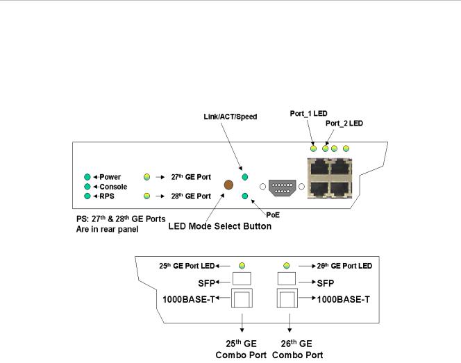
LED indicators display the status of the Switch and the network. The front panel of DES-3828P has LED indicators for power, console, RPS, 27GE (rear port), 28 GE (rear port), Link/Act/Speed, PoE, for each of the 24 10/100 Mbps Ethernet ports, and for the two 1000BASE-T/SFP ports.
Figure 1- 1. Front Panel View of the DES-3828P
DES-3828/DES-3828DC LEDs
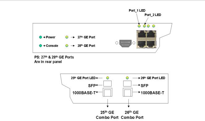
The front panel of DES-3828/DES-3828DC has LED indicators for power, console, RPS (DES-3828 only), 27GE (rear port), 28 GE (rear port), for each of the 24 10/100 Mbps Ethernet ports, and for the two 1000BASE-T/SFP ports.
3
xStack DES-3800 Series Layer 3 Stackable Fast Ethernet Managed Switch
|
|
Figure 1- 2. Front Panel View of the DES-3828DC |
|
|
|
The following table describes the LEDs for DES-3828/DES-3828P/DES-3828DC: |
|
||
|
|
|
|
|
|
LED |
Description |
|
|
|
|
|
|
|
|
Power |
Off – Power Off |
|
|
|
|
Solid Green – Power On |
|
|
|
|
|
|
|
|
Console |
Solid Green – Switch is being logged in to via the out-of-band/local console |
|
|
|
|
management through the RS-232 console port |
|
|
|
|
Blinking Green – POST is in progress |
|
|
|
|
|
|
|
|
RPS (excluding DES- |
Off – RPS off |
|
|
|
3828DC) |
Solid green – RPS in use |
|
|
|
|
|
||
|
|
|
|
|
|
Ports 27, 28 GE |
Ports 27 and 28 represent the 1000BASE-T ports located on the rear panel of the |
|
|
|
|
Switch. These port LEDs will light two different colors for 100Mbps and 1000Mbps: |
|
|
|
|
• |
Solid Green – Link or 1000Mbps |
|
|
|
• |
Blinking Green – Activity for 1000Mbps |
|
|
|
• |
Solid Amber – Link or 100Mbps |
|
|
|
• |
Blinking Amber – Activity for 100Mbps |
|
|
|
• |
Off – Link down |
|
|
|
|
|
|
|
Link/Act/Speed and |
To change the LED mode from Link/Act/Speed to PoE and vice versa, press the LED |
|
|
|
PoE (DES-3828P |
Mode Select Button. The Link/Act/Speed LED will light solid green when selected and |
|
|
|
only) |
will shut off when PoE is selected. Likewise, when Link/Act/Speed is selected, the |
|
|
|
|
PoE LED shuts off and the Link/Act/Speed LED lights solid green. |
|
|
|
|
|
|
|
4
xStack DES-3800 Series Layer 3 Stackable Fast Ethernet Managed Switch
Ports 1-24 |
One row of LEDs for each port is located above the ports on the front panel. The first |
|
|
LED is for the top port and the second one is for the bottom ports. These port LEDs |
|
|
display the following information: |
|
|
For Link/Act/Speed Mode: |
|
|
• |
Solid Green – Link or 100Mbps |
|
• |
Blinking Green – Activity for 100Mbps |
|
• |
Solid Amber – Link or 10Mbps |
|
• |
Blinking Amber – Activity for 10Mbps |
|
• |
Off – Link down |
|
For PoE Mode: (DES-3828P only) |
|
|
• |
Solid Green – Power feeding (802.3af-compliant PD was detected, legacy |
|
|
PD detected) |
|
• |
Blinking Amber - PoE port ERROR (non-standard PD connected, Under load |
|
|
state according to 802.3af (current is below I min), Overload state according |
|
|
to 802.3af (current is above Icut), hardware problems preventing port |
|
|
operation, power budget exceeded, short condition was detected at a port |
|
|
delivering power, temperature overload at the port, succession of Underload |
|
|
and Overload states caused port shutdown (may be caused by a PD’s |
|
|
DC/DC fault)...etc.) |
|
• |
Off – No power feeding (no PD detected, or no connection) |
|
|
|
Ports 25, 26 combo |
Ports 25 and 26 represent the 1000BASE-T/SFP ports located on the front panel of |
|
GE |
the Switch. These port LEDs will display the following information: |
|
|
• |
Solid Green – Link or 1000Mbps |
|
• |
Blinking Green – Activity for 1000Mbps |
|
• |
Solid Amber – Link or 100Mbps |
|
• |
Blinking Amber – Activity for 100Mbps |
|
• |
Off – Link down |
|
|
|
Rear Panel Description
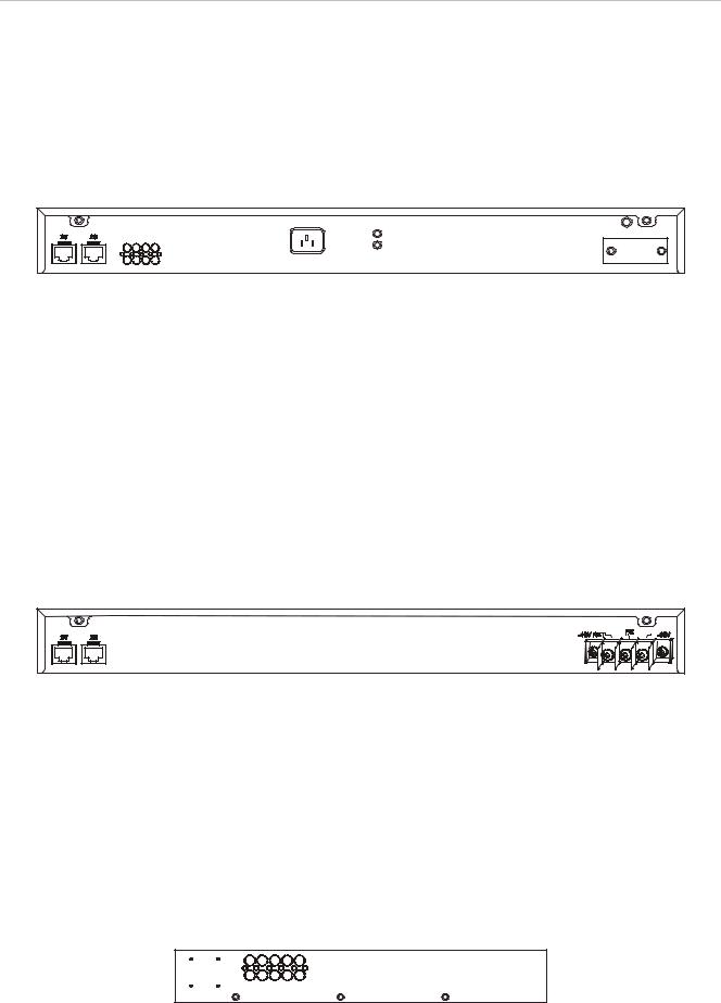
The rear panels of DES-3828, DES-3828DC and DES-3828P are described separately below:
DES-3828
The rear panel of DES-3828 contains ports 27 and 28, (1000BASE-TX), an AC power connector, and an outlet for an optional external RPS.
Figure 1- 3. Rear panel view of the DES-3828
For details on ports 27 and 28, see the “Ports” description above. The rear panel includes an outlet for an optional external redundant power supply. When power fails, the optional external RPS will take
5
xStack DES-3800 Series Layer 3 Stackable Fast Ethernet Managed Switch
over all the power immediately and automatically. The AC power connector is a standard threepronged connector that supports the power cord. Plug-in the female connector of the provided power cord into this socket, and the male side of the cord into a power outlet. The Switch automatically adjusts its power setting to any supply voltage in the range from 100 ~ 240 VAC at 50 ~ 60 Hz.
DES-3828P
The rear panel of DES-3828P contains ports 27 and 28, (1000BASE-TX), a heat vent, an AC power connector, and an outlet for an optional external RPS.
Figure 1- 4. Rear Panel view of DES-3828P
For details on ports 27 and 28, see the “Ports” description above. The rear panel includes a heat vent for the system fan. The system fan is used to dissipate heat. Do not block this opening, and leave at least 6 inches of space at the rear of the Switch for proper ventilation. Be reminded that without proper heat dissipation and air circulation, system components might overheat, which could lead to system failure. The rear panel also includes an outlet for an optional external redundant power supply. When power fails, the optional external RPS will take over all the power immediately and automatically. The AC power connector is a standard three-pronged connector that supports the power cord. Plug-in the female connector of the provided power cord into this socket, and the male side of the cord into a power outlet. The Switch automatically adjusts its power setting to any supply voltage in the range from 100 ~ 240 VAC at 50 ~ 60 Hz. The maximum output capacity for PoE is 370W. The default power feeding for PoE is set at 15.4W per port, but can be set from 1-16.8W per port. See PoE Configuration in Section 6 for instructions on how to change this setting.
DES-3828DC
Figure 1- 5. Rear panel view of DES-3828DC
The rear panel of the DC power version of the Switch includes ports 27 and 28, (1000BASE-TX), and an opening designed to accommodate the DC power wiring assembly. See the installation instructions in Section 2 for details.
Side Panel Description
The right-hand side panel of the Switch contains a system fan and ventilation along the entire right side. The left hand panel includes a system fan and a heat vent. The system fans are used to dissipate heat. Do not block these openings on either side of the Switch. Leave at least 6 inches of space at the rear and sides of the Switch for proper ventilation. Be reminded that without proper heat dissipation and air circulation, system components might overheat, which could lead to system failure.
6
xStack DES-3800 Series Layer 3 Stackable Fast Ethernet Managed Switch
Figure 1- 6. Side Panels
Gigabit Ports
In addition to the 24 10/100 Mbps ports, the Switch features two 1000BASE-T/SFP Gigabit Ethernet Combo ports on the front panel, and two 1000BASE-T copper ports on the rear panel. The diagrams below show Gigabit ports 25 and 26 on the far right of the front panel. Gigabit ports 27 and 28 are on the far left of the rear panel. Please note that PoE is not supported on either the front or rear Gigabit Ethernet ports.
Figure 1- 7. Front Panel Mini-GBIC modules plug-in to the Switch
Figure 1- 8. Rear Panel Mini-GBIC modules plug-in to the Switch
7

xStack DES-3800 Series Layer 3 Stackable Fast Ethernet Managed Switch
SECTION 2
Installation
Package Contents
Before You Connect to the Network
Installing the Switch Without the Rack
Rack Installation
Power On
Connecting DC Power to DES-3828DC
RPS Installation
Package Contents
Open the shipping carton of the Switch and carefully unpack its contents. The carton should contain the following items:
•
•
•
•
•
•
One Stand-alone Switch
One AC power cord (excluding DES-3828DC) This Manual on CD
Mounting kit (two brackets and screws) Four rubber feet with adhesive backing RS-232 console cable
If any item is found missing or damaged, please contact your local D-Link Reseller for replacement.
Before You Connect to the Network
The site where you install the Switch may greatly affect its performance. Please follow these guidelines for setting up the Switch.
•Install the Switch on a sturdy, level surface that can support at least 4.24kg (9.35lbs) of weight for DES-3828/DES-3828DC, or 6.02kg (13.27lbs) for DES-3828P. Do not place heavy objects on the Switch.
•The power outlet should be within 1.82 meters (6 feet) of the Switch.
•Visually inspect the power cord and see that it is fully secured to the AC/DC power port.
•Make sure that there is proper heat dissipation from and adequate ventilation around the Switch. Leave at least 10 cm (4 inches) of space at the front and rear of the Switch for ventilation.
•Install the Switch in a fairly cool and dry place for the acceptable temperature and humidity operating ranges.
8

xStack DES-3800 Series Layer 3 Stackable Fast Ethernet Managed Switch
•Install the Switch in a site free from strong electromagnetic field generators (such as motors), vibration, dust, and direct exposure to sunlight.
•When installing the Switch on a level surface, attach the rubber feet to the bottom of the device. The rubber feet cushion the Switch, protect the casing from scratches and prevent it from scratching other surfaces.
Installing the Switch Without the Rack
When installing the Switch on a desktop or shelf, the rubber feet included with the Switch should first be attached. Attach these cushioning feet on the bottom at each corner of the device. Allow enough ventilation space between the Switch and any other objects in the vicinity.
Rubber Feet
Figure 2 - 1. Prepare Switch for installation on a desktop or shelf
Installing the Switch in a Rack
The Switch can be mounted in a standard 19" rack. Use the following diagrams to guide you.
Figure 2 - 2. Fasten mounting brackets to Switch
Fasten the mounting brackets to the Switch using the screws provided. With the brackets attached securely, you can mount the Switch in a standard rack as shown in Figure 2-3 below.
Mounting the Switch in a Standard 19" Rack
CAUTION: Installing systems in a rack without the front and side stabilizers installed could cause the rack to tip over, potentially resulting in bodily injury under certain circumstances. Therefore, always install the stabilizers before installing components in the rack. After installing components in a rack, do not pull more than one component
9

xStack DES-3800 Series Layer 3 Stackable Fast Ethernet Managed Switch
out of the rack on its slide assemblies at one time. The weight of more than one extended component could cause the rack to tip over and may result in injury.
Figure 2 - 3. Installing Switch in a rack
Power On AC Power
Plug one end of the AC power cord into the power connector of the Switch and the other end into the local power source outlet.
After the Switch is powered on, the LED indicators will momentarily blink. This blinking of the LED indicators represents a reset of the system.
Power Failure
For AC power supply units, as a precaution, in the event of a power failure, unplug the Switch. When power is resumed, plug the Switch back in.
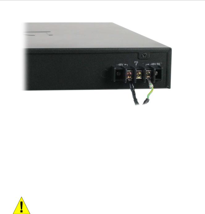
Connecting DC Power to DES-3828DC
Follow the instructions below to connect the DC power supply of the DES-3828DC to the DC power source.
10
xStack DES-3800 Series Layer 3 Stackable Fast Ethernet Managed Switch
Figure 2 - 4. Power connections attached to contacts on assembly
1.Firmly attach the DC power to the negative and positive contacts on the wiring assembly.
•The negative pole (-) connects to the -48V contact.
•The positive pole (+) connects to the -48V Return contact.
•If available, earth ground may be connected to center contact post.
2.Tighten the contact screws so the connection is secure.
RPS Installation
Follow the instructions below to connect the RPS power supply to the switch (DPS-200 to DES-3828 or DPS-600 to DES-3828P). The DPS-200 is a redundant power-supply unit designed to conform to the voltage requirements of the switches being supported. DPS-200 can be installed into DPS-900, or DPS-800.
CAUTION: The AC power cord for the switch should be disconnected before proceeding with installation of the DPS-200.
DPS-900
The DPS-900 is a standard-size rack mount (5 standard unit in height) designed to hold up to 8 DPS200 redundant power supplies.
11
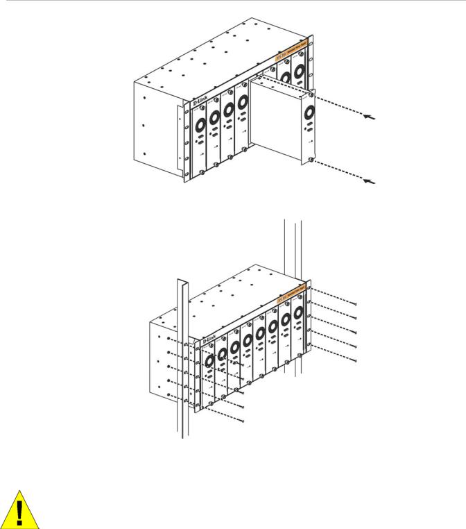
xStack DES-3800 Series Layer 3 Stackable Fast Ethernet Managed Switch
Figure 2 - 5. Install DPS-200 in DPS-900
The RPS can be mounted in a standard 19" rack. Use the following diagram to guide you.
Figure 2 - 6. Install DPS-900 in equipment rack
CAUTION: Installing systems in a rack without the front and side stabilizers installed could cause the rack to tip over, potentially resulting in bodily injury under certain circumstances. Therefore, always install the stabilizers before installing components in the rack. After installing components in a rack, do not pull more than one component out of the rack on its slide assemblies at one time. The weight of more than one extended component could cause the rack to tip over and may result in injury.
DPS-800
The DPS-800 is a standard-size rack mount (1 standard unit in height) designed to hold up to 2 DPS200 redundant power supplies.
12
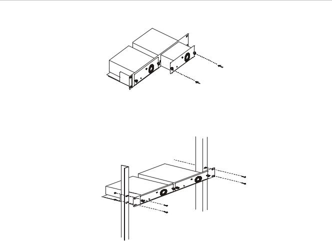
xStack DES-3800 Series Layer 3 Stackable Fast Ethernet Managed Switch
Figure 2 - 7. Install DPS-200 in DPS-800
The RPS can be mounted in a standard 19" rack. Use the following diagram to guide you.
Figure 2 - 8. Install DPS-800 in an Equipment Rack
Connect to RPS
The DPS-200 is connected to the Master Switch using a 14-pin DC power cable. A standard, threepronged AC power cable connects the redundant power supply to the main power source.
13
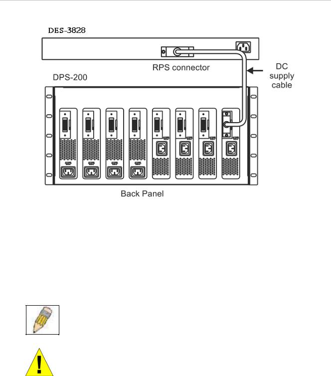
xStack DES-3800 Series Layer 3 Stackable Fast Ethernet Managed Switch
Figure 2 - 9. The DES-3828 with the DPS-200 chassis RPS
1.Insert one end of the 14-pin DC power cable into the receptacle on the switch and the other end into the redundant power supply.
2.Using a standard AC power cable, connect the redundant power supply to the main AC power source. A green LED on the front of the DPS-200 will glow to indicate a successful connection.
3.Re-connect the switch to the AC power source. On certain switches, such as the DES-3828, an LED indicator will show that a redundant power supply is now in operation.
4.No change in switch configuration is necessary for this installation.
NOTE: See the DPS-200 documentation for more information.
CAUTION: Do not use the Switch with any redundant power system other than the DPS-200 or DPS 600.
DPS-600
DES-3828P also supports the DPS-600 external redundant power supply.
14
Loading...