


 Loading...

Table of Contents |
D-Link Smart Managed Switch User Manual |
Table of Contents |
|
Table of Contents ............................................................................................................................................. |
i |
About This Guide............................................................................................................................................. |
1 |
Terms/Usage.................................................................................................................................................. |
1 |
Copyright and Trademarks ............................................................................................................................ |
1 |
Product Introduction ................................................................................................................................... |
2 |
DGS-1210-10 ................................................................................................................................................. |
3 |
Front Panel ................................................................................................................................................. |
3 |
Rear Panel.................................................................................................................................................. |
3 |
DGS-1210-10P............................................................................................................................................... |
4 |
Front Panel ................................................................................................................................................. |
4 |
Rear Panel.................................................................................................................................................. |
5 |
DGS-1210-10MP............................................................................................................................................ |
5 |
Front Panel ................................................................................................................................................. |
5 |
Rear Panel.................................................................................................................................................. |
6 |
DGS-1210-20 ................................................................................................................................................. |
6 |
Front Panel ................................................................................................................................................. |
6 |
Rear Panel.................................................................................................................................................. |
7 |
DGS-1210-26 ................................................................................................................................................. |
7 |
Front Panel ................................................................................................................................................. |
7 |
Rear Panel.................................................................................................................................................. |
8 |
DGS-1210-28 ................................................................................................................................................. |
8 |
Front Panel ................................................................................................................................................. |
8 |
Rear Panel.................................................................................................................................................. |
8 |
DGS-1210-28P............................................................................................................................................... |
9 |
Front Panel ................................................................................................................................................. |
9 |
Rear Panel................................................................................................................................................ |
10 |
DGS-1210-28MP.......................................................................................................................................... |
10 |
Front Panel ............................................................................................................................................... |
10 |
Rear Panel................................................................................................................................................ |
11 |
DGS-1210-52 ............................................................................................................................................... |
11 |
Front Panel ............................................................................................................................................... |
11 |
Rear Panel................................................................................................................................................ |
12 |
DGS-1210-52MP.......................................................................................................................................... |
12 |
Front Panel ............................................................................................................................................... |
12 |
Rear Panel................................................................................................................................................ |
13 |
LED Indicators.............................................................................................................................................. |
13 |
Hardware Installation ................................................................................................................................ |
15 |
Safety Cautions............................................................................................................................................ |
15 |
Step 1: Unpacking........................................................................................................................................ |
16 |
Step 2: Switch Installation............................................................................................................................ |
16 |
Desktop or Shelf Installation..................................................................................................................... |
16 |
Rack Installation ....................................................................................................................................... |
16 |
Step 3: Plugging in the AC Power Cord with Power Cord Clip.................................................................... |
17 |
Power Failure ........................................................................................................................................... |
20 |
Grounding the Switch ............................................................................................................................... |
20 |
Getting Started........................................................................................................................................... |
21 |
Management Options................................................................................................................................... |
21 |
i |
|

Table of Contents |
D-Link Smart Managed Switch User Manual |
Using Web-based Management .................................................................................................................. |
21 |
Supported Web Browsers ........................................................................................................................ |
21 |
Connecting to the Switch.......................................................................................................................... |
21 |
Login Web-based Management ............................................................................................................... |
21 |
Smart Wizard ............................................................................................................................................... |
22 |
Web-based Management............................................................................................................................. |
22 |
Web-based Switch Configuration ............................................................................................................ |
23 |
Smart Wizard Configuration......................................................................................................................... |
23 |
Step 1 – Web Mode.................................................................................................................................. |
23 |
Step 2 – IP Information............................................................................................................................. |
24 |
Step 3 – Password ................................................................................................................................... |
25 |
Step 4 – SNMP (Only for Standard Mode)............................................................................................... |
25 |
Web-based Management............................................................................................................................. |
27 |
Tool Bar > Save Menu ................................................................................................................................. |
28 |
Save Configuration................................................................................................................................... |
28 |
Save Log .................................................................................................................................................. |
28 |
Tool Bar > Tools Menu................................................................................................................................. |
28 |
Reset ........................................................................................................................................................ |
28 |
Reset System ........................................................................................................................................... |
28 |
Reboot Device .......................................................................................................................................... |
29 |
Configuration Backup and Restore .......................................................................................................... |
29 |
Firmware Backup and Upgrade................................................................................................................ |
30 |
Flash Information...................................................................................................................................... |
30 |
Tool Bar > Wizard ........................................................................................................................................ |
30 |
Tool Bar > Online Help................................................................................................................................. |
31 |
Tool Bar > Surveillance Mode...................................................................................................................... |
31 |
Function Tree ............................................................................................................................................... |
32 |
Device Information.................................................................................................................................... |
32 |
System > System Settings ....................................................................................................................... |
33 |
System > Password.................................................................................................................................. |
34 |
System > Port Settings............................................................................................................................. |
35 |
System > Port Description........................................................................................................................ |
35 |
System > DHCP Auto Configuration ........................................................................................................ |
36 |
System > DHCP Relay > DHCP Relay Global Settings........................................................................... |
36 |
System > DHCP Relay > DHCP Relay Interface Settings ....................................................................... |
37 |
System > DHCP Local Relay Settings ..................................................................................................... |
38 |
System > DHCPv6 Relay Settings ........................................................................................................... |
38 |
System > System Log Configuration > System Log Settings .................................................................. |
39 |
System > System Log Configuration > SysLog Host ............................................................................... |
40 |
System > Time Profile .............................................................................................................................. |
40 |
System > Power Saving ........................................................................................................................... |
41 |
System > IEEE802.3az EEE Settings ...................................................................................................... |
41 |
System > D-Link Discover Protocol Settings............................................................................................ |
42 |
System > Firmware Information ............................................................................................................... |
43 |
VLAN > 802.1Q VLAN.............................................................................................................................. |
43 |
VLAN > 802.1Q VLAN PVID .................................................................................................................... |
45 |
VLAN > Voice VLAN > Voice VLAN Global Settings ............................................................................... |
45 |
VLAN > Voice VLAN > Voice VLAN Port Settings ................................................................................... |
46 |
VLAN > Voice VLAN > Voice Device List................................................................................................. |
47 |
ii |
|

Table of Contents |
D - Link Smart Managed Switch User Manual |
||
VLAN > Auto Surveillance VLAN > Auto Surveillance Properties |
............................................................ |
47 |
|
VLAN > Auto Surveillance VLAN > MAC Settings and Surveillance Device ........................................... |
48 |
||
VLAN > Auto Surveillance VLAN > ONVIF IPC Information .................................................................... |
|
49 |
|
VLAN > Auto Surveillance VLAN > ONVIF NVR Information................................................................... |
|
49 |
|
L2 |
Functions > Jumbo Frame................................................................................................................... |
|
50 |
L2 |
Functions > Port Mirroring................................................................................................................... |
|
50 |
L2 |
Functions > Loopback Detection......................................................................................................... |
|
50 |
L2 |
Functions > MAC Address Table > Static MAC .................................................................................. |
|
51 |
L2 |
Functions > MAC Address Table > Dynamic Forwarding Table ......................................................... |
52 |
|
L2 |
Functions > Spanning Tree > STP Bridge Global Settings................................................................. |
|
52 |
L2 |
Functions > Spanning Tree > STP Port Settings ................................................................................ |
|
53 |
L2 |
Functions > Spanning Tree > MST Configuration Identification ......................................................... |
55 |
|
L2 |
Functions > Spanning Tree > STP Instance Settings ......................................................................... |
|
55 |
L2 |
Functions > Spanning Tree > MSTP Port Information ........................................................................ |
|
56 |
L2 |
Functions > Link Aggregation > Port Trunking.................................................................................... |
|
57 |
L2 |
Functions > Link Aggregation > LACP Port Settings .......................................................................... |
|
57 |
L2 |
Functions > Multicast > IGMP Snooping............................................................................................. |
|
58 |
L2 |
Functions > Multicast > MLD Snooping .............................................................................................. |
|
60 |
L2 |
Functions > Multicast > Multicast Forwarding ..................................................................................... |
|
61 |
L2 |
Functions > Multicast > Multicast Filtering Mode ................................................................................ |
|
62 |
L2 |
Functions > SNTP > Time Settings ..................................................................................................... |
|
62 |
L2 |
Functions > SNTP > TimeZone Settings............................................................................................. |
|
63 |
L2 |
Functions > LLDP > LLDP Global Settings ......................................................................................... |
|
64 |
L2 |
Functions > LLDP > LLDP-MED Settings ........................................................................................... |
|
64 |
L2 |
Functions > LLDP > LLDP Port Settings............................................................................................. |
|
65 |
L2 |
Functions > LLDP > 802.1 Extension TLV .......................................................................................... |
|
66 |
L2 |
Functions > LLDP > 802.3 Extension TLV .......................................................................................... |
|
66 |
L2 |
Functions > LLDP > LLDP Management Address Settings ................................................................ |
|
67 |
L2 Functions > LLDP > LLDP Management Address Table .................................................................... |
|
68 |
|
L2 |
Functions > LLDP > LLDP Local Port Table ....................................................................................... |
|
68 |
L2 |
Functions > LLDP > LLDP Remote Port Table ................................................................................... |
|
70 |
L2 |
Functions > LLDP > LLDP Statistics ................................................................................................... |
|
72 |
L3 |
Functions > IP Interface ...................................................................................................................... |
|
73 |
L3 |
Functions > IPv6 Neighbor Settings.................................................................................................... |
|
74 |
L3 |
Functions > IPv4 Static Route............................................................................................................. |
|
75 |
L3 |
Functions > IPv4 Routing Table Finder............................................................................................... |
|
76 |
L3 |
Functions > IPv6 Static Route............................................................................................................. |
|
76 |
L3 |
Functions > IPv6 Routing Table Finder............................................................................................... |
|
77 |
L3 |
Functions > ARP > ARP Table Global Settings .................................................................................. |
|
77 |
L3 |
Functions > ARP > Static ARP Settings.............................................................................................. |
|
78 |
QoS > Bandwidth Control......................................................................................................................... |
|
79 |
|
QoS > 802.1p/DSCP/ToS......................................................................................................................... |
|
79 |
|
Security > Trusted Host............................................................................................................................ |
|
80 |
|
Security > Port Security............................................................................................................................ |
|
81 |
|
Security > Traffic Segmentation ............................................................................................................... |
|
81 |
|
Security > Safeguard Engine.................................................................................................................... |
|
82 |
|
Security > Storm Control .......................................................................................................................... |
|
82 |
|
Security > ARP Spoofing Prevention ....................................................................................................... |
|
83 |
|
Security > DHCP Server Screening ......................................................................................................... |
|
84 |
|
|
iii |
|
|

Table of Contents |
D-Link Smart Managed Switch User Manual |
|
Security > SSL.......................................................................................................................................... |
|
84 |
Security > DoS Prevention Settings ......................................................................................................... |
|
86 |
Security > SSH > SSH Settings ............................................................................................................... |
|
86 |
Security > SSH > SSH Authmode and Algorithm Settings....................................................................... |
|
87 |
Security > SSH > SSH User Authentication Lists .................................................................................... |
|
88 |
Security > Smart Binding > Smart Binding Settings................................................................................. |
|
88 |
Security > Smart Binding > Smart Binding............................................................................................... |
|
89 |
Security > Smart Binding > White List...................................................................................................... |
|
90 |
Security > Smart Binding > Black List ...................................................................................................... |
|
90 |
AAA > RADIUS Server ............................................................................................................................. |
|
91 |
AAA > 802.1X > 802.1X Global Settings.................................................................................................. |
|
91 |
AAA > 802.1X > 802.1X Port Settings...................................................................................................... |
|
92 |
AAA > 802.1X > 802.1X User................................................................................................................... |
|
93 |
ACL > ACL Wizard ................................................................................................................................... |
|
93 |
ACL > ACL Access List .......................................................................................................................... |
|
107 |
ACL > ACL Access Group...................................................................................................................... |
|
108 |
ACL > ACL Hardware Resource Status ................................................................................................. |
|
109 |
PoE > PoE Global Settings (only for DGS-1210-10P/10MP/28P/28MP/52MP) .................................... |
109 |
|
PoE > PoE Port Settings (only for DGS-1210-10P/10MP/28P/28MP/52MP) ........................................ |
110 |
|
SNMP > SNMP > SNMP Global Settings .............................................................................................. |
|
112 |
SNMP > SNMP > SNMP User ............................................................................................................... |
|
113 |
SNMP > SNMP > SNMP Group Table ................................................................................................... |
|
113 |
SNMP > SNMP > SNMP View ............................................................................................................... |
|
114 |
SNMP > SNMP > SNMP Community..................................................................................................... |
|
114 |
SNMP > SNMP > SNMP Host................................................................................................................ |
|
115 |
SNMP > SNMP > SNMP Engine ID ....................................................................................................... |
|
115 |
SNMP > RMON > RMON Global Settings ............................................................................................. |
|
115 |
SNMP > RMON > RMON Statistics ....................................................................................................... |
|
116 |
SNMP > RMON > RMON History........................................................................................................... |
|
116 |
SNMP > RMON > RMON Alarm ............................................................................................................ |
|
116 |
SNMP > RMON > RMON Event............................................................................................................. |
|
117 |
Monitoring > Port Statistics..................................................................................................................... |
|
118 |
Monitoring > Cable Diagnostics ............................................................................................................. |
|
118 |
Monitoring > System Log........................................................................................................................ |
|
119 |
Surveillance Mode Configuration ........................................................................................................... |
|
121 |
Web User Interface .................................................................................................................................... |
|
121 |
Surveillance Overview................................................................................................................................ |
|
122 |
Surveillance Topology ............................................................................................................................ |
|
123 |
Device Information.................................................................................................................................. |
|
124 |
Port Information ...................................................................................................................................... |
|
125 |
IP-Camera Information ........................................................................................................................... |
|
125 |
NVR Information ..................................................................................................................................... |
|
125 |
PoE Information...................................................................................................................................... |
|
126 |
PoE Scheduling ...................................................................................................................................... |
|
126 |
Time > Clock Settings ............................................................................................................................ |
|
127 |
Time > SNTP Settings............................................................................................................................ |
|
127 |
Surveillance Settings.............................................................................................................................. |
|
128 |
Surveillance Log ..................................................................................................................................... |
|
130 |
Health Diagnostic ................................................................................................................................... |
|
130 |
iv |
|
|
|
Table of Contents |
D-Link Smart Managed Switch User Manual |
|
|
|
Tool Bar > Wizard ...................................................................................................................................... |
131 |
|
|
Tool Bar > Tools Menu............................................................................................................................... |
131 |
|
|
Reset System ......................................................................................................................................... |
131 |
|
|
Reboot Device ........................................................................................................................................ |
132 |
|
|
Configuration Backup & Restore ............................................................................................................ |
132 |
|
|
Firmware Backup and Upgrade.............................................................................................................. |
133 |
|
|
Firmware Information.............................................................................................................................. |
133 |
|
|
Flash Information.................................................................................................................................... |
134 |
|
|
Tool Bar > Save ......................................................................................................................................... |
134 |
|
|
Tool Bar > Help .......................................................................................................................................... |
134 |
|
|
Tool Bar > Online Help............................................................................................................................... |
135 |
|
|
Tool Bar > Standard Mode......................................................................................................................... |
135 |
|
|
Command Line Interface |
136 |
|
|
||
|
|
..............................................................................................................To connect a switch via TELNET: |
136 |
|
|
Logging on to the Command Line Interface:.............................................................................................. |
136 |
|
|
CLI Commands: ......................................................................................................................................... |
136 |
?.............................................................................................................................................................. |
137 |
||
|
|
download ................................................................................................................................................ |
138 |
|
|
upload..................................................................................................................................................... |
139 |
|
|
config firmware image_id ....................................................................................................................... |
140 |
|
|
config ipif system .................................................................................................................................... |
140 |
|
|
config ipif system .................................................................................................................................... |
141 |
|
|
logout...................................................................................................................................................... |
141 |
|
|
ping......................................................................................................................................................... |
142 |
|
|
ping6....................................................................................................................................................... |
142 |
|
|
reboot ..................................................................................................................................................... |
143 |
|
|
reset config ............................................................................................................................................. |
143 |
|
|
show boot_file......................................................................................................................................... |
143 |
|
|
show firmware information ..................................................................................................................... |
144 |
|
|
show flash information............................................................................................................................ |
145 |
|
|
show ipif.................................................................................................................................................. |
145 |
|
|
show switch ............................................................................................................................................ |
146 |
|
|
show route .............................................................................................................................................. |
146 |
|
|
config account admin password ............................................................................................................. |
147 |
|
|
save ........................................................................................................................................................ |
147 |
|
|
debug info............................................................................................................................................... |
147 |
|
Appendix A - Ethernet Technology............................................................................................................ |
149 |
|
|
|
Gigabit Ethernet Technology ..................................................................................................................... |
149 |
|
|
Fast Ethernet Technology.......................................................................................................................... |
149 |
|
|
Switching Technology ................................................................................................................................ |
149 |
|
Appendix B - Technical Specifications ..................................................................................................... |
150 |
|
|
|
Hardware Specifications ............................................................................................................................ |
150 |
|
|
Features ..................................................................................................................................................... |
154 |
|
|
L2 Features ............................................................................................................................................ |
154 |
|
|
L3 Features ............................................................................................................................................ |
154 |
|
|
VLAN ...................................................................................................................................................... |
154 |
|
|
QoS (Quality of Service)......................................................................................................................... |
154 |
|
|
Security................................................................................................................................................... |
154 |
|
|
OAM ....................................................................................................................................................... |
155 |
v

Table of Contents |
D-Link Smart Managed Switch User Manual |
Management........................................................................................................................................... |
155 |
D-Link Green Technology ...................................................................................................................... |
155 |
Appendix C – Rack mount Instructions .................................................................................................... |
156 |
Regulatory Information ............................................................................................................................... |
157 |
Federal Communication Commission Interference Statement .................................................................. |
157 |
Japan Voluntary Control Council for Interference Statement .................................................................... |
157 |
Japan Voluntary Control Council for Interference Statement .................................................................... |
157 |
: ................................................................................................................................................ |
157 |
CE EMI Class A Warning........................................................................................................................... |
157 |
SAFETY INSTRUCTIONS ......................................................................................................................... |
157 |
SICHERHEITSVORSCHRIFTEN .............................................................................................................. |
157 |
CONSIGNES DE SÉCURITÉ .................................................................................................................... |
158 |
INSTRUCCIONES DE SEGURIDAD......................................................................................................... |
158 |
ISTRUZIONI PER LA SICUREZZA ........................................................................................................... |
158 |
VEILIGHEIDSINFORMATIE ...................................................................................................................... |
159 |
Disposing of and Recycling Your Product.................................................................................................. |
159 |
vi
About This Guide |
D-Link Smart Managed Switch User Manual |
About This Guide
This guide provides instructions to install the D-Link Smart Managed Switch DGS-1210 series, and to configure Web-based Management step-by-step.
Note: The model you have purchased may appear slightly different from the illustrations shown in the document. Refer to the Product Instruction and Technical Specification sections for detailed information about your switch, its components, network connections, and technical specifications.
This guide is mainly divided into four parts:
1.Hardware Installation: Step-by-step hardware installation procedures.
2.Getting Started: A startup guide for basic switch installation and settings.
3.Web Configuration: Information about the function descriptions and configuration settings via Web.
4.Command Line Interface: Information about the function descriptions and configuration settings via Telnet.
Terms/Usage
In this guide, the term “Switch” (first letter capitalized) refers to the Smart Switch, and “switch” (first letter lower case) refers to other Ethernet switches. Some technologies refer to terms “switch”, “bridge” and “switching hubs” interchangeably, and both are commonly accepted for Ethernet switches.
A NOTE indicates important information that helps a better use of the device.
A CAUTION indicates potential property damage or personal injury.
Copyright and Trademarks
Information in this document is subjected to change without notice. © 2017 D-Link Corporation. All rights reserved.
Reproduction in any manner whatsoever without the written permission of D-Link Corporation is strictly forbidden.
Trademarks used in this text: D-Link and the D-LINK logo are trademarks of D-Link Corporation; Microsoft and Windows are registered trademarks of Microsoft Corporation.
Other trademarks and trade names may be used in this document to refer to either the entities claiming the marks and names or their products. D-Link Corporation disclaims any proprietary interest in trademarks and trade names other than its own.
1

1 Product Introduction |
D-Link Smart Managed Switch User Manual |
1 Product Introduction
Thank you and congratulations on your purchase of D-Link Smart Managed Switch Products.
D-Link's next generation Smart Managed switch series blends plug-and-play simplicity with exceptional value and reliability for small and medium-sized business (SMB) networking. All models are housed in a new style rack-mount metal case with easy-to-view front panel diagnostic LEDs, and provides advanced features including network security, traffic segmentation, QoS and versatile management.
Flexible Port Configurations. The DGS-1210 series is the new generation of Smart Managed Switch series. It provides 8, 16, 24 or 48 10/100/1000Mbps Non-PoE or PoE ports plus 4 GE/SFP ports. All switches of the DGS-1210 series feature embedded 4 gigabit SFP uplinks, which provides flexible network topology choices such as ring, tree, or mixed.
D-Link Green Technology. D-Link Green devices are about providing eco-friendly alternatives without compromising performance. D-Link Green Technology includes a number of innovations to reduce energy consumption on DGS-1210 series such as shutting down a port, or turning off some LED indicators, or adjusting the power usage according to the Ethernet cable connected to it.
Extensive Layer 2 Features. Implemented as complete L2 devices, these switches include functions such as IGMP snooping, port mirroring, Spanning Tree, 802.3ad LACP and Loopback Detection to enhance performance and network resiliency.
Traffic Segmentation, QoS and Auto Surveillance VLAN. The switches support 802.1Q VLAN standard tagging to enhance network security and performance. The switches also support 802.1p priority queues, enabling users to run bandwidth-sensitive applications such as streaming multimedia by prioritizing that traffic in network. These functions allow switches to work seamlessly with VLAN and 802.1p traffic in the network. Auto Surveillance VLAN will automatically place the vedio traffic from pre-defined IP surveillance devices to an assigned VLAN with higher priority, so it can be separated from normal data traffic. Asymmetric VLAN is implemented in these switches for a more efficient use of shared resources, such as server or gateway devices.
Network Security. D-Link’s innovative Safeguard Engine function protects the switches against traffic flooding caused by virus attacks. Additional features like 802.1X port-based authentication provide access control of the network with external RADIUS servers. ACL is a powerful tool to screen unwanted IP or MAC traffic. Storm Control can help to keep the network from being overwhelmed by abnormal traffic. Port Security is another simple but useful authentication method to maintain the network device integrity.
Versatile Management. The new generation of D-Link Smart Managed Switches provides growing businesses simple and easy management of their network. The multi-language Web-Based management interface allows administrators to remotely control their network down to the port level. The intuitive easily allows customers to discover multiple D-Link Smart Managed Switches in the same L2 network segment. With this utility, users do not need to change the IP address of PC and provides easy initial setting of smart switches. The switches within the same L2 network segment connected to user’s local PC are displayed on the screen for instant access. It allows extensive switch configuration setting, and basic configuration of discovered devices such as a password change or firmware upgrade.
Users can also access the Switch via Telnet. Basic tasks such as changing the Switch IP address, resetting the settings to factory defaults, setting the administrator password, rebooting the Switch, or upgrading the Switch firmware can be performed using the Command Line Interface (CLI)
In addition, users can utilize the SNMP MIB (Management Information Base) to poll the switches for information about the status, or send out traps of abnormal events. SNMP support allows users to integrate
2

1 Product Introduction |
D-Link Smart Managed Switch User Manual |
the switches with other third-party devices for management in an SNMP-enabled environment. D-Link Smart Managed Switches provides easy-to-use graphic interface and facilitates the operation efficiency.
DGS-1210-10
8-Port 10/100/1000Mbps plus 2 SFP ports (100/1000Mbps) Smart Managed Switch.
Front Panel
Figure 1.1 – DGS-1210-10 Front Panel
The front panel of the DGS-1210-10 switch consists out of the following:
•Power LED : The Power LED lights up when the Switch is connected to a power source.
•Port Link/Act/Speed LED (1-8): The Link/Act/Speed LED flashes, which indicates a network link through the corresponding port. Blinking indicates that the Switch is either sending or receiving data to the port. When a port has an amber light, this indicates that the port is running on 10M or 100M. When it has a green light it is running on 1000M.
•Port Link/Act/Speed LED (9F, 10F): The Link/Act/Speed LED flashes, which indicates a network link through the corresponding port. Blinking indicates that the Switch is either sending or receiving data to the port. When the port LED glows in amber, it indicates the port is running on 100M. When the port LED glows in green, it is running on 1000Mbps.
•Reset: Press the Reset button for 1~5 seconds to reboot the device. Press the Reset button for 6~10 seconds to reset the Switch back to the default settings and led will be solid light with amber for 2 seconds. Or press the Reset button over 11 seconds to enter the loader mode after device reboot and the led will be solid light with green for 2 seconds. If the device cannot reboot the Switch via image 1 and image 2, the device will enter the loader mode automatically.
CAUTION: The MiniGBIC ports should use UL listed Optical
Transceiver product, Rated Laser Class I. 3.3Vdc.
NOTE: Once user enter in loader mode, you can use DNA tool (standalone version 2.0.2.4 only (No support by Chrome DNA3.x.x.x)) to download the image or call D-Link Technical Support for further help.
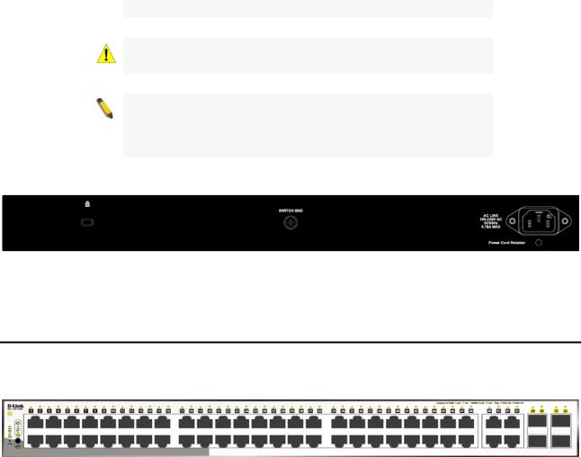
Rear Panel
Figure 1.2 – DGS-1210-10 Rear Panel
Power: Connect the supplied AC power cable to this port.
3
1 Product Introduction |
D-Link Smart Managed Switch User Manual |
DGS-1210-10P
8-Port 10/100/1000Mbps plus 2 SFP Ports (100/1000Mbps) Smart Managed PoE Switch.
Front Panel
Figure 1.3 – DGS-1210-10P Front Panel
The front panel of the DGS-1210-10P switch consists out of the following:
•Power LED : The Power LED lights up when the Switch is connected to a power source.
•PoE Max: The PoE Max LED lights up with solid red when the Switch reaches the maximum power budget defined by the administrator via PoE System Settings page of Web GUI or the default power budget of 65 Watts.
•Port Link/Act/Speed LED (1-8): The Link/Act/Speed LED flashes, which indicates a network link through the corresponding port. Blinking indicates that the Switch is either sending or receiving data to the port. When a port has an amber light, this indicates that the port is running on 10M or 100M. When it has a green light it is running on 1000M.
•Port Link/Act/Speed LED (9F, 10F): The Link/Act/Speed LED flashes, which indicates a network link through the corresponding port. Blinking indicates that the Switch is either sending or receiving data to the port. When the port LED glows in amber, it indicates the port is running on 100M. When the port LED glows in green, it is running on 1000Mbps.
•LED Mode: To select the mode of port LED, the Link/Act and PoE LED under the mode button will solid green to indicate which mode is selected.
•Mode: By pressing the Mode button, the Port LED will switch between Link/Act and PoE modes.
•Reset: Press the Reset button for 1~5 seconds to reboot the device. Press the Reset button for 6~10 seconds to reset the Switch back to the default settings and led will be solid light with amber for 2 seconds. Or press the Reset button over 11 seconds to enter the loader mode after device reboot and the led will be solid light with green for 2 seconds. If the device cannot reboot the Switch via image 1 and image 2, the device will enter the loader mode automatically.
CAUTION: The MiniGBIC ports should use UL listed Optical
Transceiver product, Rated Laser Class I. 3.3Vdc.
CAUTION: The port 1 ~ port 8 are PoE ports. When user press the
Mode button to PoE mode, only port 1 ~ port 8 will light up.
CAUTION: This equipment can be connected only to PoE networks without routing to the outside plant.
NOTE: Once user enter in loader mode, you can use DNA tool (standalone version 2.0.2.4 only (No support by Chrome DNA3.x.x.x)) to download the image or call D-Link Technical Support for further help.
4
1 Product Introduction |
D-Link Smart Managed Switch User Manual |
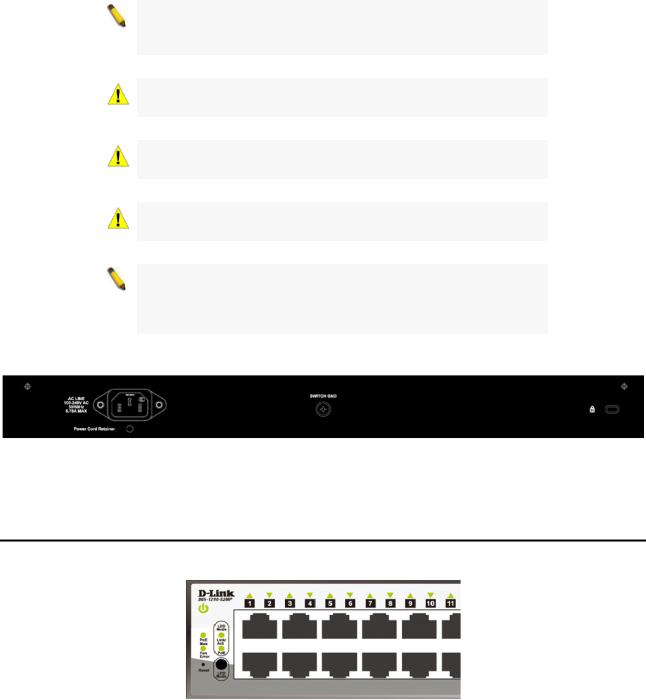
Rear Panel
Figure 1.4 – DGS-1210-10P Rear Panel
Power: Connect the supplied DC external power 54V/1.574A cable to this port.
DGS-1210-10MP
8-Port 10/100/1000Mbps plus 2 SFP Ports (100/1000Mbps) Smart Managed PoE Switch.
Front Panel
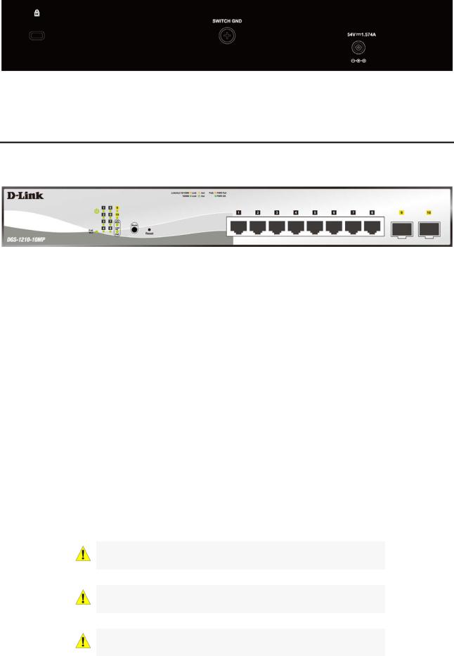
Figure 1.5 – DGS-1210-10MP Front Panel
The front panel of the DGS-1210-10MP switch consists out of the following:
•Power LED : The Power LED lights up when the Switch is connected to a power source.
•PoE Max: The PoE Max LED lights up with solid red when the Switch reaches the maximum power budget defined by the administrator via PoE System Settings page of Web GUI or the default power budget of 130 Watts.
•Port Link/Act/Speed LED (1-8): The Link/Act/Speed LED flashes, which indicates a network link through the corresponding port. Blinking indicates that the Switch is either sending or receiving data to the port. When a port has an amber light, this indicates that the port is running on 10M or 100M. When it has a green light it is running on 1000M.
•Port Link/Act/Speed LED (9F, 10F): The Link/Act/Speed LED flashes, which indicates a network link through the corresponding port. Blinking indicates that the Switch is either sending or receiving data to the port. When the port LED glows in amber, it indicates the port is running on 100M. When the port LED glows in green, it is running on 1000Mbps.
•LED Mode: To select the mode of port LED, the Link/Act and PoE LED under the mode button will solid green to indicate which mode is selected.
•Mode: By pressing the Mode button, the Port LED will switch between Link/Act and PoE modes.
•Reset: Press the Reset button for 1~5 seconds to reboot the device. Press the Reset button for 6~10 seconds to reset the Switch back to the default settings and led will be solid light with amber for 2 seconds. Or press the Reset button over 11 seconds to enter the loader mode after device reboot and the led will be solid light with green for 2 seconds. If the device cannot reboot the Switch via image 1 and image 2, the device will enter the loader mode automatically.
CAUTION: The MiniGBIC ports should use UL listed Optical
Transceiver product, Rated Laser Class I. 3.3Vdc.
CAUTION: The port 1 ~ port 8 are PoE ports. When user press the
Mode button to PoE mode, only port 1 ~ port 8 will light up.
CAUTION: This equipment can be connected only to PoE networks without routing to the outside plant.
5
1 Product Introduction |
D-Link Smart Managed Switch User Manual |
NOTE: Once user enter in loader mode, you can use DNA tool (standalone version 2.0.2.4 only (No support by Chrome DNA3.x.x.x)) to download the image or call D-Link Technical Support for further help.
Rear Panel
Figure 1.6 – DGS-1210-10MP Rear Panel
Power: Connect the supplied AC power cable to this port.
DGS-1210-20
16-Port 10/100/1000Mbps plus 4 Combo GE/SFP Slot Smart Managed Switch.
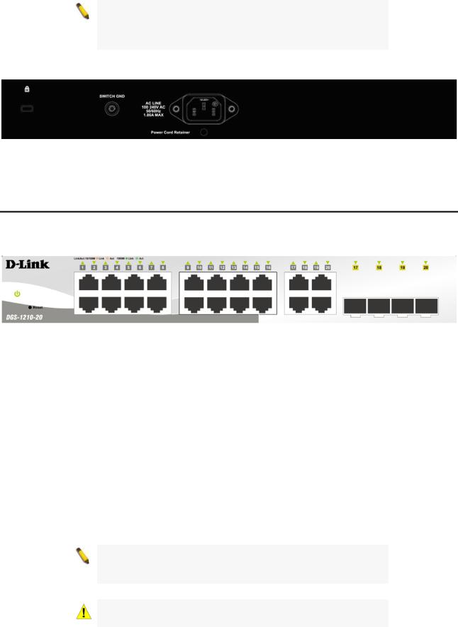
Front Panel
Figure 1.7 – DGS-1210-20 Front Panel
The front panel of the DGS-1210-20 switch consists out of the following:
•Power LED : The Power LED lights up when the Switch is connected to a power source.
•Port Link/Act/Speed LED (1-16): The Link/Act/Speed LED flashes, which indicates a network link through the corresponding port. Blinking indicates that the Switch is either sending or receiving data to the port. When a port has an amber light, this indicates that the port is running on 10M or 100M. When it has a green light it is running on 1000M.
•Port Link/Act/Speed LED (17F, 18F, 19F, 20F, 17T, 18T, 19T, 20T): The Link/Act/Speed LED flashes, which indicates a network link through the corresponding port. Blinking indicates that the Switch is either sending or receiving data to the port. When the port LED glows in amber, it indicates the port is running on 100M. When the port LED glows in green, it is running on 1000Mbps.
•Reset: Press the Reset button for 1~5 seconds to reboot the device. Press the Reset button for 6~10 seconds to reset the Switch back to the default settings and led will be solid light with amber for 2 seconds. Or press the Reset button over 11 seconds to enter the loader mode after device reboot and the led will be solid light with green for 2 seconds. If the device cannot reboot the Switch via image 1 and image 2, the device will enter the loader mode automatically.
NOTE: On the DGS-1210-20, the MiniGBIC ports are shared with normal RJ-45 ports 17T, 18T, 19T and 20T. When the MiniGBIC port is used, the RJ-45 port cannot be used.
CAUTION: The MiniGBIC ports should use UL listed Optical
Transceiver product, Rated Laser Class I. 3.3Vdc.
6
1 Product Introduction |
D-Link Smart Managed Switch User Manual |
NOTE: Once user enter in loader mode, you can use DNA tool (standalone version 2.0.2.4 only (No support by Chrome DNA3.x.x.x)) to download the image or call D-Link Technical Support for further help.
Rear Panel
Figure 1.8 – DGS-1210-20 Rear Panel
Power: Connect the supplied AC power cable to this port.
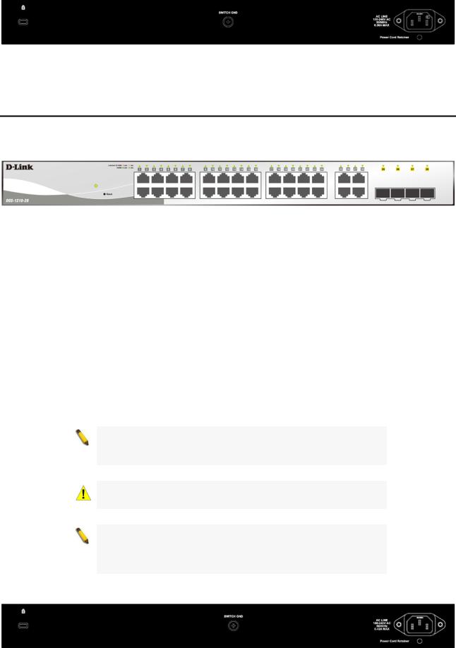
DGS-1210-26
24-Port 10/100/1000Mbps plus 2 SFP Ports (100/1000Mbps) Smart Managed Switch.
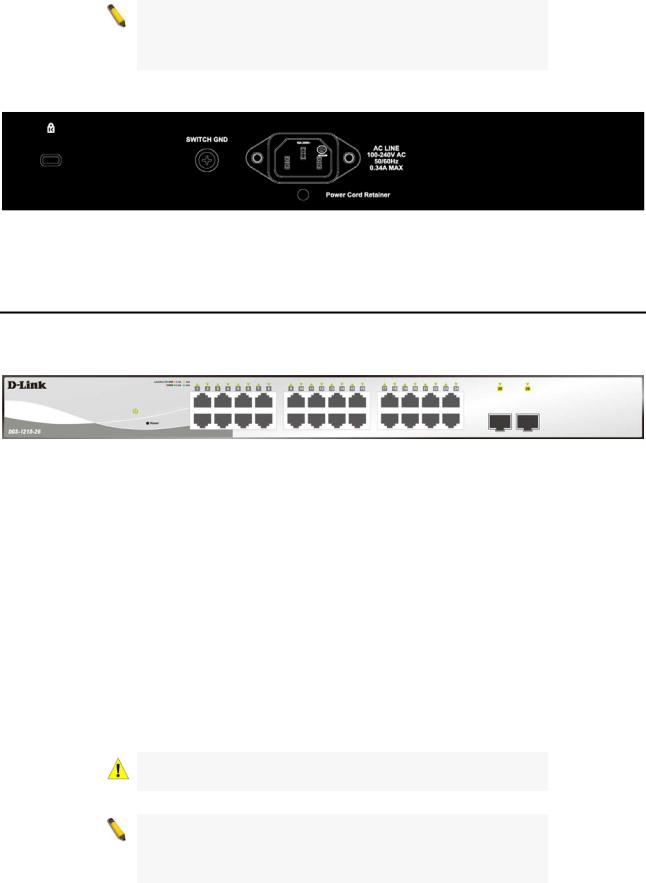
Front Panel
Figure 1.9 – DGS-1210-26 Front Panel
The front panel of the DGS-1210-26 switch consists out of the following:
•Power LED : The Power LED lights up when the Switch is connected to a power source.
•Port Link/Act/Speed LED (1-24): The Link/Act/Speed LED flashes, which indicates a network link through the corresponding port. Blinking indicates that the Switch is either sending or receiving data to the port. When a port has an amber light, this indicates that the port is running on 10M or 100M. When it has a green light it is running on 1000M.
•Port Link/Act/Speed LED (25F, 26F): The Link/Act/Speed LED flashes, which indicates a network link through the corresponding port. Blinking indicates that the Switch is either sending or receiving data to the port. When the port LED glows in amber, it indicates the port is running on 100M. When the port LED glows in green, it is running on 1000Mbps.
•Reset: Press the Reset button for 1~5 seconds to reboot the device. Press the Reset button for 6~10 seconds to reset the Switch back to the default settings and led will be solid light with amber for 2 seconds. Or press the Reset button over 11 seconds to enter the loader mode after device reboot and the led will be solid light with green for 2 seconds. If the device cannot reboot the Switch via image 1 and image 2, the device will enter the loader mode automatically.
CAUTION: The MiniGBIC ports should use UL listed Optical
Transceiver product, Rated Laser Class I. 3.3Vdc.
NOTE: Once user enter in loader mode, you can use DNA tool (standalone version 2.0.2.4 only (No support by Chrome DNA3.x.x.x)) to download the image or call D-Link Technical Support for further help.
7
1 Product Introduction |
D-Link Smart Managed Switch User Manual |
Rear Panel
Figure 1.10 – DGS-1210-26 Rear Panel
Power: Connect the supplied AC power cable to this port.
DGS-1210-28
24-Port 10/100/1000Mbps plus 4 Combo GE/SFP Slot Smart Managed Switch.
Front Panel
Figure 1.11 – DGS-1210-28 Front Panel
The front panel of the DGS-1210-28 switch consists out of the following:
•Power LED : The Power LED lights up when the Switch is connected to a power source.
•Port Link/Act/Speed LED (1-24): The Link/Act/Speed LED flashes, which indicates a network link through the corresponding port. Blinking indicates that the Switch is either sending or receiving data to the port. When a port has an amber light, this indicates that the port is running on 10M or 100M. When it has a green light it is running on 1000M.
•Port Link/Act/Speed LED (25F, 26F, 27F, 28F, 25T, 26T, 27T, 28T): The Link/Act/Speed LED flashes, which indicates a network link through the corresponding port. Blinking indicates that the Switch is either sending or receiving data to the port. When the port LED glows in amber, it indicates the port is running on 100M. When the port LED glows in green, it is running on 1000Mbps.
•Reset: Press the Reset button for 1~5 seconds to reboot the device. Press the Reset button for 6~10 seconds to reset the Switch back to the default settings and led will be solid light with amber for 2 seconds. Or press the Reset button over 11 seconds to enter the loader mode after device reboot and the led will be solid light with green for 2 seconds. If the device cannot reboot the Switch via image 1 and image 2, the device will enter the loader mode automatically.
NOTE: On the DGS-1210-28, the MiniGBIC ports are shared with normal RJ-45 ports 25T, 26T, 27T and 28T. When the MiniGBIC port is used, the RJ-45 port cannot be used.
CAUTION: The MiniGBIC ports should use UL listed Optical
Transceiver product, Rated Laser Class I. 3.3Vdc.
NOTE: Once user enter in loader mode, you can use DNA tool (standalone version 2.0.2.4 only (No support by Chrome DNA3.x.x.x)) to download the image or call D-Link Technical Support for further help.
Rear Panel
8
1 Product Introduction |
D-Link Smart Managed Switch User Manual |
Figure 1.12 – DGS-1210-28 Rear Panel
Power: Connect the supplied AC power cable to this port.
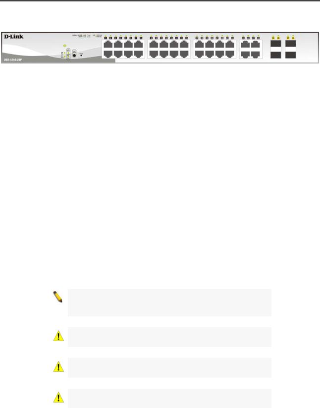
DGS-1210-28P
24-Port 10/100/1000Mbps plus 4 Combo GE/SFP Smart Managed PoE Switch.
Front Panel
Figure 1.13 – DGS-1210-28P Front Panel
The front panel of the DGS-1210-28P switch consists out of the following:
•Power LED : The Power LED lights up when the Switch is connected to a power source.
•Fan Error: The FAN LED shows the status of the fans, light off indicates all fans work fine and the red light indicates that one or multiple fans are working abnormally.
•PoE Max: The PoE Max LED lights up with solid red when the Switch reaches the maximum power budget defined by the administrator via PoE System Settings page of Web GUI or the default power budget of 193 Watts.
•LED Mode: To select the mode of port LED, the Link/Act and PoE LED under the mode button will solid green to indicate which mode is selected.
•Port Link/Act/Speed LED (1-24): The Link/Act/Speed LED flashes, which indicates a network link through the corresponding port. Blinking indicates that the Switch is either sending or receiving data to the port. When a port has an amber light, this indicates that the port is running on 10M or 100M. When it has a green light it is running on 1000M.
•Port Link/Act/Speed LED (25F, 26F, 27F, 28F, 25T, 26T, 27T, 28T): The Link/Act/Speed LED flashes, which indicates a network link through the corresponding port. Blinking indicates that the Switch is either sending or receiving data to the port. When the port LED glows in amber, it indicates the port is running on 100M. When the port LED glows in green, it is running on 1000Mbps.
•Reset: Press the Reset button for 1~5 seconds to reboot the device. Press the Reset button for 6~10 seconds to reset the Switch back to the default settings and led will be solid light with amber for 2 seconds. Or press the Reset button over 11 seconds to enter the loader mode after device reboot and the led will be solid light with green for 2 seconds. If the device cannot reboot the Switch via image 1 and image 2, the device will enter the loader mode automatically.
•LED Mode: By pressing the Mode button, the Port LED will switch between Link/Act and PoE modes.
NOTE: On the DGS-1210-28P, the MiniGBIC ports are shared with normal RJ-45 ports 25T, 26T, 27T and 28T. When the MiniGBIC port is used, the RJ-45 port cannot be used.
CAUTION: The MiniGBIC ports should use UL listed Optical
Transceiver product, Rated Laser Class I. 3.3Vdc.
CAUTION: The port 1 ~ port 24 are PoE ports. When user press the Mode button to PoE mode, only port 1 ~ port 24 will light up.
CAUTION: This equipment can be connected only to PoE networks without routing to the outside plant.
9
1 Product Introduction |
D-Link Smart Managed Switch User Manual |
NOTE: Once user enter in loader mode, you can use DNA tool (standalone version 2.0.2.4 only (No support by Chrome DNA3.x.x.x)) to download the image or call D-Link Technical Support for further help.
Rear Panel
Figure 1.14 – DGS-1210-28P Rear Panel
Power: Connect the supplied AC power cable to this port.
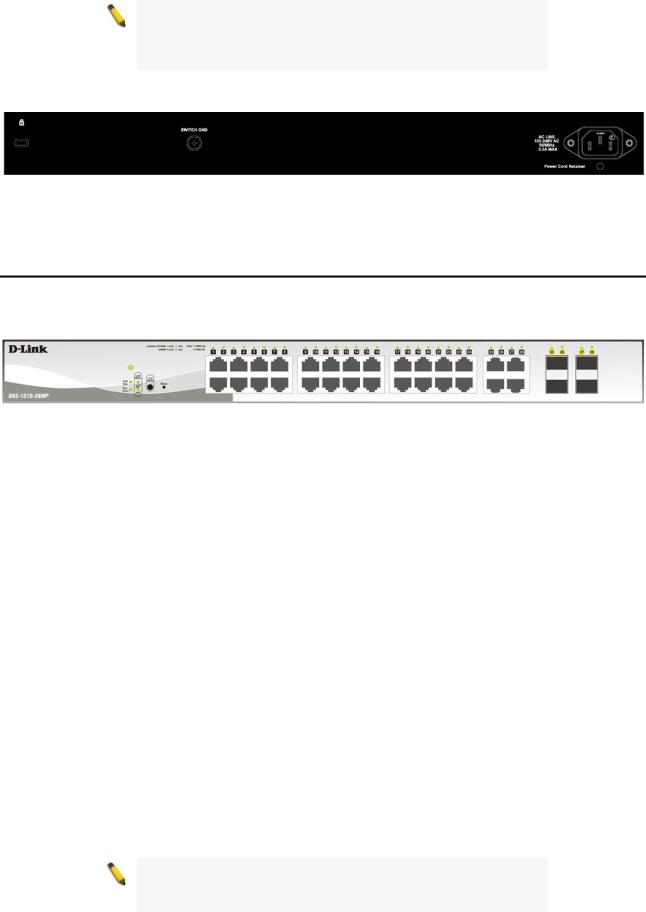
DGS-1210-28MP
24-Port 10/100/1000Mbps plus 4 combo GE/SFP Slot Smart Managed PoE Switch.
Front Panel
Figure 1.15 – DGS-1210-28MP Front Panel
The front panel of the DGS-1210-28MP switch consists out of the following:
•Power LED : The Power LED lights up when the Switch is connected to a power source.
•Fan Error: The FAN LED shows the status of the fans, light off indicates all fans work fine and the red light indicates that one or multiple fans are working abnormally.
•PoE Max: The PoE Max LED lights up with solid red when the Switch reaches the maximum power budget defined by the administrator via PoE System Settings page of Web GUI or the default power budget of 370 Watts.
•LED Mode: To select the mode of port LED, the Link/Act and PoE LED under the mode button will solid green to indicate which mode is selected.
•Port Link/Act/Speed LED (1-24): The Link/Act/Speed LED flashes, which indicates a network link through the corresponding port. Blinking indicates that the Switch is either sending or receiving data to the port. When a port has an amber light, this indicates that the port is running on 10M or 100M. When it has a green light it is running on 1000M.
•Port Link/Act/Speed LED (25F, 26F, 27F, 28F, 25T, 26T, 27T, 28T): The Link/Act/Speed LED flashes, which indicates a network link through the corresponding port. Blinking indicates that the Switch is either sending or receiving data to the port. When the port LED glows in amber, it indicates the port is running on 100M. When the port LED glows in green, it is running on 1000Mbps.
•Reset: Press the Reset button for 1~5 seconds to reboot the device. Press the Reset button for 6~10 seconds to reset the Switch back to the default settings and led will be solid light with amber for 2 seconds. Or press the Reset button over 11 seconds to enter the loader mode after device reboot and the led will be solid light with green for 2 seconds. If the device cannot reboot the Switch via image 1 and image 2, the device will enter the loader mode automatically.
•LED Mode: By pressing the Mode button, the Port LED will switch between Link/Act and PoE modes.
NOTE: On the DGS-1210-28MP, the MiniGBIC ports are shared with normal RJ-45 ports 25T, 26T, 27T and 28T. When the MiniGBIC port is used, the RJ-45 port cannot be used.
10
1 Product Introduction |
D-Link Smart Managed Switch User Manual |
CAUTION: The MiniGBIC ports should use UL listed Optical
Transceiver product, Rated Laser Class I. 3.3Vdc.
CAUTION: The port 1 ~ port 24 are PoE ports. When user press the Mode button to PoE mode, only port 1 ~ port 24 will light up.
CAUTION: This equipment can be connected only to PoE networks without routing to the outside plant.
NOTE: Once user enter in loader mode, you can use DNA tool (standalone version 2.0.2.4 only (No support by Chrome DNA3.x.x.x)) to download the image or call D-Link Technical Support for further help.
Rear Panel
Figure 1.16 – DGS-1210-28MP Rear Panel
Power: Connect the supplied AC power cable to this port.
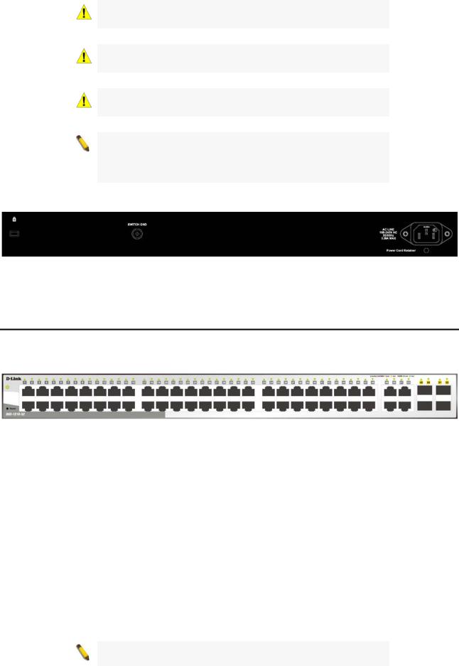
DGS-1210-52
48-Port 10/100/1000Mbps plus 4 Combo GE/SFP Slot Smart Managed Switch.
Front Panel
Figure 1.17 – DGS-1210-52 Front Panel
The front panel of the DGS-1210-52 switch consists out of the following:
•Power LED : The Power LED lights up when the Switch is connected to a power source.
•Port Link/Act/Speed LED (1-48): The Link/Act/Speed LED flashes, which indicates a network link through the corresponding port. Blinking indicates that the Switch is either sending or receiving data to the port. When a port has an amber light, this indicates that the port is running on 10M or 100M. When it has a green light it is running on 1000M.
•Port Link/Act/Speed LED (49F, 50F, 51F, 52F, 49T, 50T, 51T, 52T): The Link/Act/Speed LED flashes, which indicates a network link through the corresponding port. Blinking indicates that the Switch is either sending or receiving data to the port. When the port LED glows in amber, it indicates the port is running on 100M. When the port LED glows in green, it is running on 1000Mbps.
•Reset: Press the Reset button for 1~5 seconds to reboot the device. Press the Reset button for 6~10 seconds to reset the Switch back to the default settings and led will be solid light with amber for 2 seconds. Or press the Reset button over 11 seconds to enter the loader mode after device reboot and the led will be solid light with green for 2 seconds. If the device cannot reboot the Switch via image 1 and image 2, the device will enter the loader mode automatically.
NOTE: On the DGS-1210-52, the MiniGBIC ports are shared with normal RJ-45 ports 49T, 50T, 51T and 52T. When the MiniGBIC
11
1 Product Introduction |
D-Link Smart Managed Switch User Manual |
port is used, the RJ-45 port cannot be used.
CAUTION: The MiniGBIC ports should use UL listed Optical
Transceiver product, Rated Laser Class I. 3.3Vdc.
NOTE: Once user enter in loader mode, you can use DNA tool (standalone version 2.0.2.4 only (No support by Chrome DNA3.x.x.x)) to download the image or call D-Link Technical Support for further help.
Rear Panel
Figure 1.18 – DGS-1210-52 Rear Panel
Power: Connect the supplied AC power cable to this port.
DGS-1210-52MP
48-Port 10/100/1000Mbps plus 4 Combo GE/SFP Smart Managed PoE Switch.
Front Panel
Figure 1.19 – DGS-1210-52MP Front Panel
The front panel of the DGS-1210-52MP switch consists out of the following:
•Power LED : The Power LED lights up when the Switch is connected to a power source.
•Fan Error: The FAN LED shows the status of the fans, light off indicates all fans work fine and the red light indicates that one or multiple fans are working abnormally.
•PoE Max: The PoE Max LED lights up with solid red when the Switch reaches the maximum power budget defined by the administrator via PoE System Settings page of Web GUI or the default power budget of 370 Watts.
•LED Mode: To select the mode of port LED, the Link/Act and PoE LED under the mode button will solid green to indicate which mode is selected.
•Port Link/Act/Speed LED (1-48): The Link/Act/Speed LED flashes, which indicates a network link through the corresponding port. Blinking indicates that the Switch is either sending or receiving data to the port. When a port has an amber light, this indicates that the port is running on 10M or 100M. When it has a green light it is running on 1000M.
•Port Link/Act/Speed LED (49F, 50F, 51F, 52F, 49T, 50T, 51T, 52T): The Link/Act/Speed LED flashes, which indicates a network link through the corresponding port. Blinking indicates that the Switch is either sending or receiving data to the port. When the port LED glows in amber, it indicates the port is running on 100M. When the port LED glows in green, it is running on 1000Mbps.
•Reset: Press the Reset button for 1~5 seconds to reboot the device. Press the Reset button for 6~10 seconds to reset the Switch back to the default settings and led will be solid light with amber for 2 seconds. Or press the Reset button over 11 seconds to enter the loader mode after device reboot and the led will be solid light with green for 2 seconds. If the device cannot reboot the Switch via image 1 and image 2, the device will enter the loader mode automatically.
•LED Mode: By pressing the Mode button, the Port LED will switch between Link/Act and PoE modes.
12
1 Product Introduction |
D-Link Smart Managed Switch User Manual |
NOTE: On the DGS-1210-52MP, the MiniGBIC ports are shared with normal RJ-45 ports 49T, 50T, 51T and 52T. When the MiniGBIC port is used, the RJ-45 port cannot be used.
CAUTION: The MiniGBIC ports should use UL listed Optical
Transceiver product, Rated Laser Class I. 3.3Vdc.
CAUTION: The port 1 ~ port 48 are PoE ports. When user press the Mode button to PoE mode, only port 1 ~ port 48 will light up.
CAUTION: This equipment can be connected only to PoE networks without routing to the outside plant.
NOTE: Once user enter in loader mode, you can use DNA tool (standalone version 2.0.2.4 only (No support by Chrome DNA3.x.x.x)) to download the image or call D-Link Technical Support for further help.
Rear Panel
Figure 1.20 – DGS-1210-52MP Rear Panel
Power: Connect the supplied AC power cable to this port.
LED Indicators
The Switch supports LED indicators for Power, Fan, and Link/Act for each port. The following shows the LED indicators for the DGS-1210 series Smart Managed Switch along with an explanation of each indicator.
Figure 1.21 –LED Indicators on DGS-1210 series
Location |
LED Indicative |
Color |
Status |
Description |
|
|
|
|
|
|
|
|
Power |
Green |
Solid Light |
Power on. |
|
|
|
|
|||
Per Device |
Light off |
Power off. |
|||
|
|
||||
|
|
|
|
||
Fan Error |
Red |
Solid light |
The fan has runtime failure and is |
||
|
|||||
|
(For DGS-1210- |
||||
|
28P/28MP/52MP) |
|
|
brought offline. |
|
|
|
|
|
||
|
|
|
|
|
13
1 Product Introduction |
|
D-Link Smart Managed Switch User Manual |
||
|
|
|
|
|
|
|
|
|
The PoE Max LED lights up when |
|
|
|
|
the total PoE output of Switch |
|
|
|
|
reached or exceeded 65 Watts for |
|
|
|
Solid light |
DGS-1210-10P, 130 Watts for |
|
|
|
DGS-1210-10MP, 193 Watts for |
|
|
|
|
|
DGS-1210-28P, and 370 Watts |
|
PoE Max. |
|
|
for DGS-1210-28MP/52MP. In the |
|
(For DGS-1210- |
Amber |
|
meantime, no additional PoE |
|
10P/10MP/28P/28MP/52MP) |
|
|
device can be supported. |
|
|
Blinking |
Total PoE output of Switch |
|
|
|
|
||
|
|
|
reached guard band mode. (Max. |
|
|
|
|
Amber |
|
|
|
|
PoE budget < 7 Watts ) |
|
|
|
|
|
|
|
|
|
|
When the system power usage |
|
|
|
Light off |
does not reach the guard band |
|
|
|
|
range. |
|
|
|
Solid |
When there is a secure 1000Mbps |
|
|
|
Ethernet connection (or link) at |
|
|
|
|
Green |
|
|
|
|
any of the ports. |
|
|
|
|
|
|
|
|
|
|
When there is reception or |
|
|
|
Blinking |
transmission (i.e. Activity—Act) of |
|
|
|
Green |
data occurring at a 1000Mbps |
|
|
|
|
Ethernet connected port. |
|
Link/Act |
Green/Amber |
Solid |
When there is a secure |
LED Per |
|
|
Amber |
10/100Mbps Ethernet connection |
|
|
(or link) at any of the ports. |
||
|
|
|
||
10/100/1000Mbps |
|
|
|
When there is reception or |
Copper Port |
|
|
Blinking |
transmission (i.e. Activity—Act) of |
|
|
|
Amber |
data occurring at a 10/100Mbps |
|
|
|
|
Ethernet connected port. |
|
|
|
Light off |
No link. |
|
|
|
|
|
|
|
Green |
Solid Light |
Power feeding. |
|
PoE Mode |
|
|
|
|
Amber |
Solid Light |
Error Condition. |
|
|
|
|
|
|
|
|
Off |
Solid Off |
No Power feeding. |
|
|
|
|
|
|
|
|
Solid |
When there is a secure 1000Mbps |
|
|
|
Ethernet connection (or link) at |
|
|
|
|
Green |
|
|
|
|
any of the ports. |
|
|
|
|
|
|
|
|
|
|
When there is reception or |
|
|
|
Blinking |
transmission (i.e. Activity—Act) of |
|
|
|
Green |
data occurring at a 1000Mbps |
LED Per |
|
Green/Amber |
|
Ethernet connected port. |
|
Solid |
When there is a secure 100Mbps |
||
100/1000Mbps |
Link/Act |
|
||
|
Ethernet connection (or link) at |
|||
SFP Port |
|
|
Amber |
|
|
|
any of the ports. |
||
|
|
|
|
|
|
|
|
|
When there is reception or |
|
|
|
Blinking |
transmission (i.e. Activity—Act) of |
|
|
|
Amber |
data occurring at a 100Mbps |
|
|
|
|
Ethernet connected port. |
|
|
Off |
Solid off |
No link. |
|
|
|
|
|
14

2 Hardware Installation |
D-Link Smart Managed Switch User Manual |
2 Hardware Installation
This chapter provides unpacking and installation information for the D-Link Smart Managed Switch.
Safety Cautions
To reduce the risk of bodily injury, electrical shock, fire and damage to the equipment, observe the following precautions:
•Observe and follow service markings
Do not service any product except as explained in your system documentation.
Opening or removing covers that are marked with the triangular symbol with a lightning bolt may expose you to electrical shock.
•Only a trained service technician should service components inside these compartments.
•If any of the following conditions occur, unplug the product from the electrical outlet and replace the part or contact your trained service provider:
The power cable, extension cable, or plug is damaged.
An object has fallen into the product.
The product has been exposed to water.
The product has been dropped or damaged.
The product does not operate correctly when you follow the operating instructions.
•Keep your system away from radiators and heat sources. Also, do not block cooling vents.
•Do not spill food or liquids on your system components, and never operate the product in a wet environment. If the system gets wet, contact your trained service provider.
•Do not push any objects into the openings of your system. Doing so can cause fire or electric shock by shorting out interior components.
•Use the product only with approved equipment.
•Allow the product to cool before removing covers or touching internal components.
•Operate the product only from the type of external power source indicated on the electrical ratings label. If you are not sure of the type of power source required, consult your service provider or local power company.
•Also, be sure that attached devices are electrically rated to operate with the power available in your location.
•Use only approved power cable(s). If you have not been provided with a power cable for your system or for any AC powered option intended for your system, purchase a power cable that is approved for use in your country. The power cable must be rated for the product and for the voltage and current marked on the product’s electrical ratings label. The voltage and current rating of the cable should be greater than the ratings marked on the product.
•To help prevent electric shock, plug the system and peripheral power cables into properly grounded electrical outlets.
•These cables are equipped with three-prong plugs to help ensure proper grounding. Do not use adapter plugs or remove the grounding prong from a cable. If you must use an extension cable, use a 3-wire cable with properly grounded plugs.
•Observe extension cable and power strip ratings. Make sure that the total ampere rating of all products plugged into the extension cable or power strip does not exceed 80 percent of the ampere ratings limit for the extension cable or power strip.
•To help protect your system from sudden, transient increases and decreases in electrical power, use a surge suppressor, line conditioner, or uninterruptible power supply (UPS).
•Position system cables and power cables carefully; route cables so that they cannot be stepped on or tripped over. Be sure that nothing rests on any cables.
•Do not modify power cables or plugs. Consult a licensed electrician or your power company for site modifications.
•Always follow your local/national wiring rules.
15

2 Hardware Installation |
D-Link Smart Managed Switch User Manual |
•When connecting or disconnecting power to hot-pluggable power supplies, if offered with your system, observe the following guidelines:
Install the power supply before connecting the power cable to the power supply.
Unplug the power cable before removing the power supply.
If the system has multiple sources of power, disconnect power from the system by unplugging all power cables from the power supplies.
•Move products with care; ensure that all casters and/or stabilizers are firmly connected to the system. Avoid sudden stops and uneven surfaces.
Step 1: Unpacking
Open the shipping carton and carefully unpack its contents. Please consult the packing list located in the User Manual to make sure all items are present and undamaged. If any item is missing or damaged, please contact your local D-Link reseller for replacement.
One D-Link DGS-1210 Smart Managed Switch
One Multilingual Getting Started Guide
User Guide CD
Power cord and Power Cord Retainer or external power adapter(DGS-1210-10P only)
Rack-mount kit and rubber feet
If any item is found missing or damaged, please contact the local reseller for replacement.
Step 2: Switch Installation
For safe switch installation and operation, it is recommended that you:
Visually inspect the power cord to see that it is secured fully to the AC power connector. Make sure that there is proper heat dissipation and adequate ventilation around the switch. Do not place heavy objects on the switch.
Desktop or Shelf Installation
When installing the switch on a desktop or shelf, the rubber feet included with the device must be attached on the bottom at each corner of the device’s base. Allow enough ventilation space between the device and the objects around it.
Figure 2.1 – Attach the adhesive rubber pads to the bottom
Rack Installation
The switch can be mounted in an EIA standard size 19-inch rack, which can be placed in a wiring closet with other equipment. To install, attach the mounting brackets to the switch’s side panels (one on each side) and secure them with the screws provided (please note that these brackets are not designed for palm size switches).
16
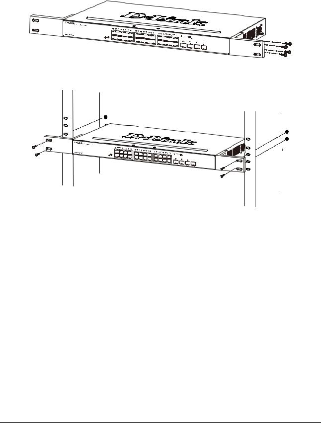
2 Hardware Installation |
|
|
|
|
|
|
|
D-Link Smart Managed Switch User Manual |
||||||||||||||||||||||||
|
|
|
|
|
|
|
|
|
|
|
|
|
|
|
|
|
|
|
|
|
|
|
|
|
|
|
|
|
|
|
|
|
|
|
|
|
|
|
|
|
|
|
|
|
|
|
|
|
|
|
|
|
|
|
|
|
|
|
|
|
|
|
|
|
|
|
|
|
|
|
|
|
|
|
|
|
|
|
|
|
|
|
|
|
|
|
|
|
|
|
|
|
|
|
|
|
|
|
|
|
|
|
|
|
|
|
|
|
|
|
|
|
|
|
|
|
|
|
|
|
|
|
|
|
|
|
|
|
|
|
|
|
|
|
|
|
|
|
|
|
|
|
|
|
|
|
|
|
|
|
|
|
|
|
|
|
|
|
|
|
|
|
|
|
Figure 2.2 – Attach the mounting brackets to the Switch
Then, use the screws provided with the equipment rack to mount the switch in the rack.
Figure 2.3 – Mount the Switch in the rack or chassis
Please be aware of following safety Instructions when installing:
A)Elevated Operating Ambient - If installed in a closed or multi-unit rack assembly, the operating ambient temperature of the rack environment may be greater than room ambient. Therefore, consideration should be given to installing the equipment in an environment compatible with the maximum ambient temperature (Tma) specified by the manufacturer.
B)Reduced Air Flow - Installation of the equipment in a rack should be such that the amount of air flow required for safe operation of the equipment is not compromised.
C)Mechanical Loading - Mounting of the equipment in the rack should be such that a hazardous condition is not achieved due to uneven mechanical loading.
D)Circuit Overloading - Consideration should be given to the connection of the equipment to the supply circuit, and the effect that overloading of the circuits might have on overcurrent protection and supply wiring. Appropriate consideration of equipment nameplate ratings should be used when addressing this concern.
E)Reliable Earthing - Reliable earthing of rack-mounted equipment should be maintained. Particular attention should be given to supply connections other than direct connections to the branch circuit (e.g. use of power strips)."
Step 3: Plugging in the AC Power Cord with Power Cord Clip
To prevent accidental removal of the AC power cord, it is recommended to install the power cord clip together with the power cord.
A) With the rough side facing down, insert the Tie Wrap into the hole below the power socket.
17
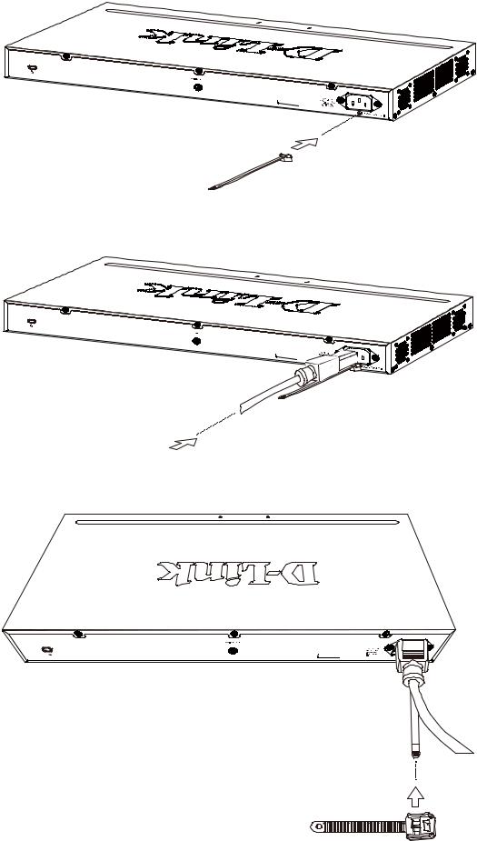
2 Hardware Installation |
D-Link Smart Managed Switch User Manual |
|||||
|
|
|
|
|
|
|
|
|
|
|
|
|
|
Figure 2.4 – Insert Tie Wrap to the Switch
B) Plug the AC power cord into the power socket of the Switch.
Figure 2.5 – Connect the power cord to the Switch
C) Slide the Retainer through the Tie Wrap until the end of the cord.
Figure 2.6 – Slide the Retainer through the Tie Wrap
18
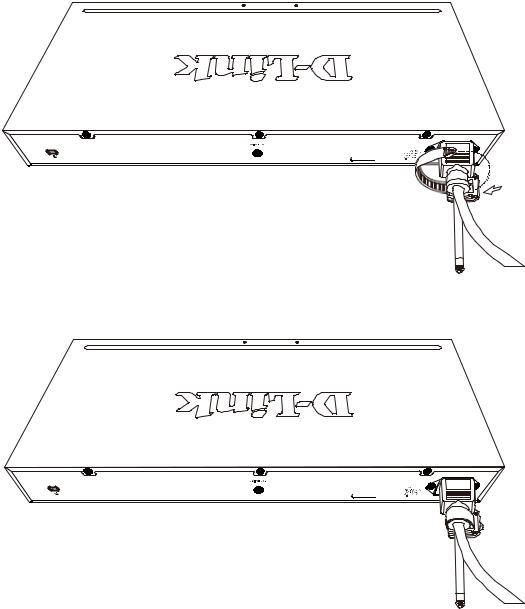
2 Hardware Installation |
D-Link Smart Managed Switch User Manual |
D) Circle the tie of the Retainer around the power cord and into the locker of the Retainer.
Figure 2.7 – Circle around the power cord
E) Fasten the tie of the Retainer until the power cord is secured.
Figure 2.8 – Secure the power cord
F) Users may now connect the AC power cord to an electrical outlet (preferably one that is grounded and surge protected).
19
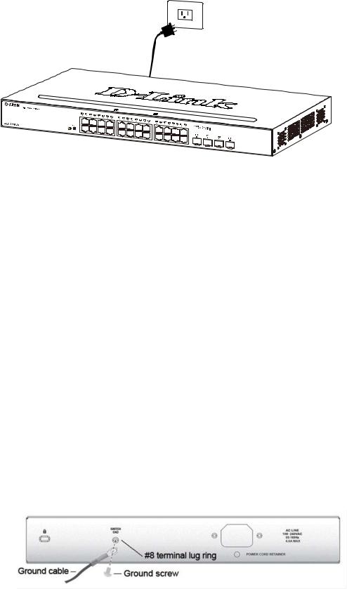
2 Hardware Installation |
D-Link Smart Managed Switch User Manual |
Figure 2.9 – Plugging the switch into an outlet
Power Failure
As a precaution, the switch should be unplugged in case of power failure. When power is resumed, plug the switch back in.
Grounding the Switch
This section describes how to connect the DGS-1210 Series Switch to ground. You must complete this procedure before powering your switch.
Required Tools and Equipment
•Ground screws (included in the accessory kit): One M4 x 6 mm (metric) pan-head screw.
•Ground cable (not included in the accessory kit): The grounding cable should be sized according to local and national installation requirements. Depending on the power supply and system, a 12 to 6 AWG copper conductor is required for U.S installation. Commercially available 6 AWG wire is recommended. The length of the cable depends on the proximity of the switch to proper grounding facilities.
•A screwdriver (not included in the accessory kit)
The following steps let you connect the switch to a protective ground: Step 1: Verify if the system power is off.
Step 2: Use the ground cable to place the #8 terminal lug ring on top of the ground-screw opening, as seen in the figure below.
Step 3: Insert the ground screw into the ground-screw opening.
Step 4: Using a screwdriver, tighten the ground screw to secure the ground cable to the switch.
Step 5: Attach the terminal lug ring at the other end of the grounding cable to an appropriate grounding stud or bolt on rack where the switch is installed.
Step 6: Verify if the connections at the ground connector on the switch and the rack are securely attached.
Figure 2.10 – Connect a Grounding Cable
20
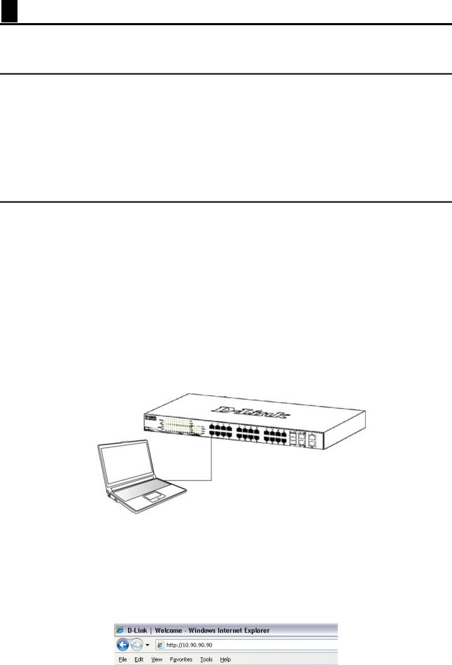
3 Getting Started |
D-Link Smart Managed Switch User Manual |
3 Getting Started
This chapter introduces the management interface of D-Link Smart Managed Switch.
Management Options
The D-Link Smart Managed Switch can be managed through any port on the device by using the Web-based Management.
Each switch must be assigned its own IP Address, which is used for communication with Web-Based Management or a SNMP network manager. The PC should have an IP address in the same range as the switch. Each switch can allow up to four users to access to the Web-Based Management concurrently. Please refer to the following installation instructions for the Web-based Management.
Using Web-based Management
After a successful physical installation, you can configure the Switch, monitor the network status, and display statistics using a web browser.
Supported Web Browsers
The embedded Web-based Management currently supports the following web browsers: Web Browser via IE8(or later version), Firefox, Chrome and Safari.
Connecting to the Switch
You will need the following equipment to begin the web configuration of your device:
1.A PC with a RJ-45 Ethernet connection
2.A standard Ethernet cable
Connect the Ethernet cable to any of the ports on the front panel of the switch and to the Ethernet port on the PC.
Figure 3.1 – Connected Ethernet cable
Login Web-based Management
In order to login and configure the switch via an Ethernet connection, the PC must have an IP address in the same subnet as the switch. For example, if the switch has an IP address of 10.90.90.90, the PC should have an IP address of 10.x.y.z (where x/y is a number between 0 ~ 254 and z is a number between 1 ~ 254), and a subnet mask of 255.0.0.0. There are two ways to launch the Web-based Management, you may either click the Web Access button at the top of the SmartConsole Utility or open the web browser and enter 10.90.90.90 (the factory-default IP address) in the address bar. Then press <Enter>.
21
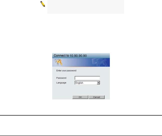
3 Getting Started |
D-Link Smart Managed Switch User Manual |
Figure 3.2 –Enter the IP address 10.90.90.90 in the web browser
NOTE: The switch's factory default IP address is 10.90.90.90 with a subnet mask of 255.0.0.0 and a default gateway of 0.0.0.0.
The web configuration can also be accessed through the SmartConsole Utility. Open the SmartConsole Utility and double-click the switch as it appears in the Monitor List. This will automatically load the web configuration in your web browser.
When the following logon dialog box appears, enter the password and choose the language of the Webbased Management interface then click OK.
The switch supports 10 languages including English, Traditional Chinese, Simplified Chinese, German, Spanish, French, Italian, Portuguese, Japanese and Russian. By default, the password is admin and the language is English.
Figure 3.3 – Logon Dialog Box
Smart Wizard
After a successful login, the Smart Wizard will guide you through essential settings of the D-Link Smart Managed Switch. Please refer to the Smart Wizard Configuration section for details.
Web-based Management
By clicking the Exit button in the Smart Wizard, you will enter the Web-based Management interface. Please refer to Chapter 4 Web-based Switch Configuration for detailed instructions.
22
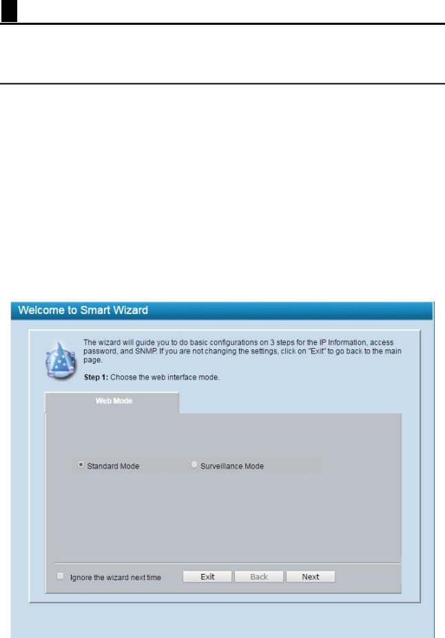
4 Web-based Switch Configuration |
D-Link Smart Managed Switch User Manual |
4 Web-based Switch Configuration
The features and functions of the D-Link Smart Managed Switch can be configured for optimum use through the Web-based Management Utility.
Smart Wizard Configuration
The Smart Wizard is a configuration utility that is launched the first time the Web UI is accessed. It allows users to configure basic settings such as the switch mode, management IP, password and SNMP. It can also be used to switch between Standard Mode and Surveillance Mode Web UI types.
Standard Mode is used to manage the network and system elements of the switch. Surveillance Mode is a dedicated user interface designed for monitoring and managing the surveillance and IP security device on your network.
To switch between the two types of interfaces, you can re-run the Smart Wizard that is presented when you access the web interface of the device.
Step 1 – Web Mode
After a successful login, the Smart Wizard will guide you through essential settings of the D-Link Smart Managed Switch. The initial page allows the user to choose between Standard Mode and Surveillance Mode on the switch. This can be changed at any time by returning to the Smart Wizard.
If you do not plan to change anything, click Exit to leave the Wizard and enter the Web Interface. You can also skip it by clicking Ignore the Wizard next time for the next time you logon to the Web-based Management.
Figure 4.1 – Web Mode in Smart Wizard
23
Loading...