


Table of Contents
Table of Contents
Safety Instructions...................................................... |
3 |
Safety Cautions....................................................... |
3 |
Protecting Against Electrostatic Discharge.............. |
6 |
Product Overview........................................................ |
7 |
Package Contents................................................... |
7 |
Setup....................................................................... |
7 |
Introduction.............................................................. |
8 |
Features................................................................. |
11 |
Hardware Overview............................................... |
12 |
Front Panel (LEDs).......................................... |
12 |
RearPanelConnections)( ................................ |
15 |
Installation.................................................................. |
16 |
Before You Connect to the Network....................... |
16 |
Mounting the Switch on the............................Wall |
17 |
Mounting on a cement..............................wall |
17 |
Mounting on a wood.................................wall |
17 |
Connecting the Switch........................................... |
18 |
DGS-2205to End Node................................... |
18 |
Hub/SwitchtoDGS-2205................................. |
18 |
Connecting To Network Backbone...or Server |
18 |
Troubleshooting......................................................... |
19 |
Glossary..................................................................... |
20 |
NetworkingBasics.................................................... |
27 |
Check your IP address.......................................... |
27 |
StaticallyAssignan IP address............................. |
28 |
Technical Specifications........................................... |
29 |
DGS-2205 Specifications...................................... |
29 |
RJ-45 Pin Specifications........................................ |
30 |
Contacting Technical Support.................................. |
31 |
Warranty..................................................................... |
32 |
Registration................................................................ |
37 |
D-Link DGS-2205 User Manual |
2 |

Section 1 - Safety Instructions
Safety Instructions
Use the following safety guidelines to ensure your own personal safety and to help protect your system from potential damage.
Safety Cautions
To reduce the risk of bodily injury, electrical shock, fire, and damage to the equipment, observe the following precautions.
Observe and follow service markings. Do not service any product except as explained in your system documentation. Opening or removing covers that are marked with the triangular symbol with a lightning bolt may expose you to an electrical shock. Only a trained service technician should service components inside these compartments.
If any of the following conditions occur, unplug the product from the electrical outlet and replace the part or contact your trained service provider:
–The power cable, extension cable, or plug is damaged.
–An object has fallen into the product.
–The product has been exposed to water.
–The product has been dropped or damaged.
–The product does not operate correctly when you follow the operating instructions.
•Keep your system away from radiators and heat sources. Also, do not block cooling vents.
•Do not spill food or liquids on your system components, and never operate the product in a wet environment. If the system gets wet, see the appropriate section in your troubleshooting guide or contact your trained service provider.
D-Link DGS-2205 User Manual |
3 |

Section 1 - Safety Instructions
•Do not push any objects into the openings of your system. Doing so can cause a fire or an electric shock by shorting out interior components.
•Use the product only with approved equipment.
•Allow the product to cool before removing covers or touching internal components.
•Operate the product only from the type of external power source indicated on the electrical ratings label. If you are not sure of the type of power source required, consult your service provider or local power company.
•To help avoid damaging your system, be sure the voltage selection switch (if provided) on the power supply is set to match the power available at your location:
–115 volts (V)/60 hertz (Hz) in most of North and South America and some Far Eastern countries such as South Korea and Taiwan.
–100 V/50 Hz in eastern Japan and 100 V/60 Hz in western Japan.
–230 V/50 Hz in most of Europe, the Middle East, and the Far East.
•Also be sure that attached devices are electrically rated to operate with the power available in your location.
•Use only approved power cable(s). If you have not been provided with a power cable for your system or for any AC-powered option intended for your system, purchase a power cable that is approved for use in your country. The power cable must be rated for the product and for the voltage and current marked on the product’s electrical ratings label. The voltage and current rating of the cable should be greater than the ratings marked on the product.
•To help prevent an electric shock, plug the system and peripheral power cables into properly grounded electrical outlets.These cables are equipped with three-prong plugs to help ensure proper grounding. Do not use adapter plugs or remove the grounding prong from a cable. If you must use an extension cable, use a 3-wire cable with properly grounded plugs.
D-Link DGS-2205 User Manual |
4 |

Section 1 - Safety Instructions
•Observe extension cable and power strip ratings. Make sure that the total ampere rating of all products plugged into the extension cable or power strip does not exceed 80 percent of the ampere ratings limit for the extension cable or power strip.
•To help protect your system from sudden, transient increases and decreases in electrical power, use a surge suppressor, line conditioner, or uninterruptible power supply (UPS).
•Position system cables and power cables carefully; route cables so that they cannot be stepped on or tripped over. Be sure that nothing rests on any cables.
•Do not modify power cables or plugs.Consult a licensed electrician or your power company for site modifications. Always follow your local/national wiring rules.
•When connecting or disconnecting power to hot-pluggable power supplies, if offered with your system, observe the following guidelines:
–Install the power supply before connecting the power cable to the power supply.
–Unplug the power cable before removing the power supply.
–If the system has multiple sources of power, disconnect power from the system by unplugging all power cables from the power supplies.
•Move products with care; ensure that all casters and/or stabilizers are firmly connected to the system. Avoid sudden stops and uneven surfaces.
D-Link DGS-2205 User Manual |
5 |

Section 1 - Safety Instructions
Protecting Against Electrostatic Discharge
Static electricity can harm delicate components inside your system.To prevent static damage, discharge static electricity from your body before you touch any of the electronic components, such as the microprocessor. You can do so by periodically touching an unpainted metal surface on the chassis.
You can also take the following steps to prevent damage from electrostatic discharge (ESD):
1.When unpacking a static-sensitive component from its shipping carton, do not remove the component from the antistatic packing material until you are ready to install the component in your system. Just before unwrapping the antistatic packaging, be sure to discharge static electricity from your body.
2.When transporting a sensitive component, first place it in an antistatic container or packaging.
3.Handle all sensitive components in a static-safe area. If possible, use antistatic floor pads, workbench pads, and an antistatic grounding strap.
D-Link DGS-2205 User Manual |
6 |
Section 2 - Product Overview
ProductPackageOverviewContents
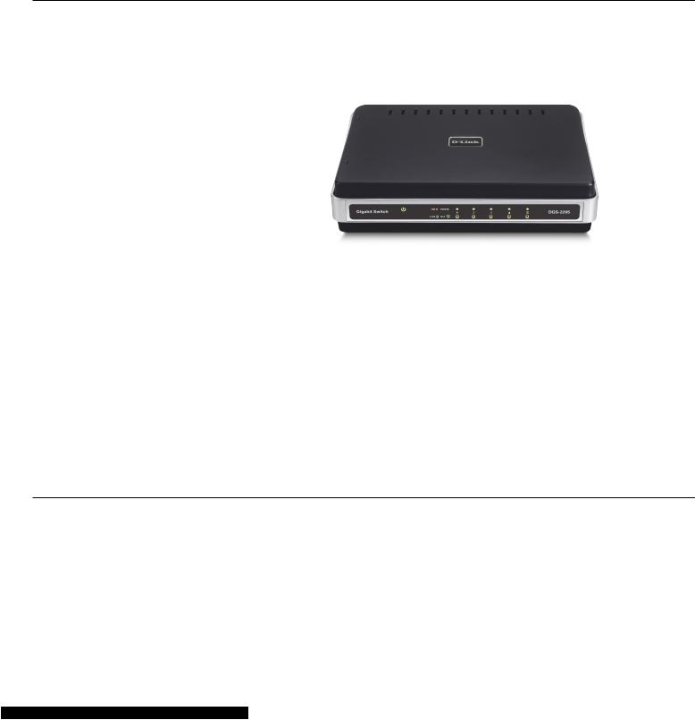
•D-Link DGS-2205-port Switch
•Manual and Warranty on CD
•Four (4) Rubber Feet
•Wall Mount Kit
•Power Adapter
Setup
The setup of the DGS-2205 can be performed using the following steps:
•The power outlet should be within 1.82 meters (6 feet) of the Switch.
•Visually inspect the DC power jack and make sure that it is fully secured to the power adapter.
•Do not cover the ventilation holes on the sides of the Switch, and make sure there is adequate ventilation around it.
•Do not place heavy objects on the switch.
D-Link DGS-2205 User Manual |
7 |

Section 2 - Product Overview
Introduction
Fast Ethernet Technology
The growing importance of LANs and the increasing complexity of desktop computing applications are fueling the need for high performance networks.100BASE-TX (Fast Ethernet) provides a cost-effective and high-performance solution for small workgroups, SMBs (Small to Medium Businesses), and any network supporting bandwidth-intensive applications. Fast Ethernet technology operates at 10 times the speed of traditional Ethernet, offering maximum performance and enhanced capability for existing Ethernet-based networks.
100Mbps Fast Ethernet is a standard specified by the IEEE 802.3 LAN committee. It is an extension of the 10Mbps Ethernet standard with the ability to transmit and receive data at 100Mbps, while maintaining the CSMA/CD Ethernet protocol. Since the 100Mbps Fast Ethernet is compatible with all other 10Mbps Ethernet environments, it provides a straightforward upgrade and takes advantage of the existing investment in hardware, software, and personnel training.
Gigabit Ethernet Technology
Gigabit Ethernet is an extension of IEEE 802.3 Ethernet utilizing the same packet structure, format, and support for CSMA/CD protocol, full duplex, flow control, and management objects, but with a tenfold increase in theoretical throughput over 100Mbps Fast Ethernet and a one hundred-fold increase over 10Mbps Ethernet.Since it is compatible with all 10Mbps and 100Mbps Ethernet environments, Gigabit Ethernet provides a straightforward upgrade without wasting a company’s existing investment in hardware, software, and trained personnel.
The increased speed and extra bandwidth offered by Gigabit Ethernet are essential to coping with the network bottlenecks that frequently develop as computers and their busses get faster and more users use applications that generate more traffic.Upgrading key components, such as your backbone and servers to Gigabit Ethernet can greatly improve network response times as well as significantly speed up the traffic between your subnetworks.
Gigabit Ethernet enables fast optical fiber connections to support video conferencing, complex imaging, and similar data-intensive applications. Likewise, since data transfers occur 10 times faster than Fast Ethernet, servers outfitted with Gigabit Ethernet NIC’s are able to perform 10 times the number of operations in the same amount of time.
In addition, the phenomenal bandwidth delivered by Gigabit Ethernet is the most cost-effective method to take advantage of today and tomorrow’s rapidly improving switching and routing internetworking technologies.
D-Link DGS-2205 User Manual |
8 |

Section 2 - Product Overview
Switching Technology
Switching is a cost-effective way of increasing the total network capacity available to users on a LAN. If an Ethernet network begins to display symptoms of congestion, low throughput, slow response times, and high rates of collision, installing a switch to a network can preserve much or all of the existing network’s cabling and workstation interface card infrastructure, while still greatly enhancing the throughput for users. A switch is a viable solution even if demanding applications, such as multimedia production and video conferencing, are on the horizon.The most promising techniques, as well as the best return on investment, could well consist of installing the right mixture of Ethernet switches.
A switch increases capacity and decreases network loading by dividing a local area network into different LAN segments. Dividing a LAN into multiple segments is one of the most common ways of increasing available bandwidth. If segmented correctly, most network traffic will remain within a single segment, enjoying the full-line speed bandwidth of that segment.
Switches provide full-line speed and dedicated bandwidth for all connections.This is in contrast to hubs, which use the traditional shared networking topology, where the connected nodes contend for the same network bandwidth. When two switching nodes are communicating, they are connected with a dedicated channel between them, so there is no contention for network bandwidth with other nodes. As a result, the switch reduces considerably, the likelihood of traffic congestion.
For Ethernet networks, a switch is an effective way of eliminating the problem of chaining hubs beyond the “two-repeater limit.” A switch can be used to split parts of the network into different collision domains, making it possible to expand your Ethernet network beyond the 205-meter network diameter limit for 100BASE-TX networks. Switches supporting both 10Mbps Ethernet and 100Mbps Fast Ethernet are also ideal for bridging between existing 10Mbps networks and newer 100Mbps networks.
Switching LAN technology is a marked improvement over the previous generation of network hubs and bridges, which were characterized by higher latencies. Routers have also been used to segment local area networks, but the cost of a router, the setup and maintenance required, make routers relatively impractical.Today switches are an ideal solution to most kinds of local area network congestion problems.
D-Link DGS-2205 User Manual |
9 |

Section 2 - Product Overview
802.1p PriorityTagging
802.1p places a tag in a frame to indicate the priority of the frame. A tag will represent a priority of 0-7 and an 802.1p compliant switch can read this tag and prioritize traffic accordingly. In 802.1p a port can receive frames with varying priority tags and classify them based on these tags. A VoIP phone that supports 802.1p can assign a priority to its VoIP traffic and when it enters the switch the switch can give it a higher priority so that voice traffic is always clear and jitter free.The DGS-2205 supports the 802.1p feature with 4 preconfigured priority queues.When a frame tagged with an 802.1p priority bit is received by the switch it places the frame into one of 4 queues prioritized according to its tag number. For example, traffic tagged with a priority bit of 7 will have a higher priority then traffic tagged with a priority bit of 6 and so forth.
Jumbo Frame Support
The DGS-2205 switch supports Jumbo Frames up to (9K) in size.Jumbo Frame support is designed to improve network throughput and significantly reduce the CPU utilization of large file transfers such as multimedia files or large data files by enabling more efficient larger payloads per packet.
D-Link DGS-2205 User Manual |
10 |
Section 2 - Product Overview
Features
The DGS-2205 5-Port 10/100/1000BASE-T Gigabit Ethernet Switch was designed for easy installation and high performance in an environment where traffic on the network and the number of users increase continuously.
•Five (5) 10/100/1000BASE-T Gigabit Ethernet ports
•Cable Diagnostic function at Switch boot up
•Supports Auto-Negotiation for 10/100/1000Mbps and duplex mode
•Supports Auto-MDI/MDIX for each port
•Supports Full/Half duplex transfer mode for 10 and 100Mbps
•Supports Full-duplex transfer mode for 1000Mbps
•Supports IEEE 802.1p Priority Queuing, up to 4 queues
•Full wire speed reception and transmission
•Store-and-Forward switching method
•Supports 8K absolute MAC addresses
•Extensive front-panel diagnostic LEDs
•Jumbo FrameKbytes9
•IEEE 802.3x flow control for full duplex
•Back pressure flow control for half duplex
D-Link DGS-2205 User Manual |
11 |
Section 2 - Product Overview
Hardware Overview
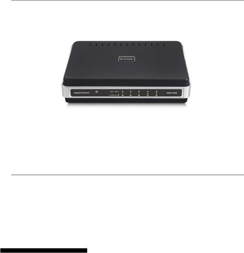
Front Panel (LEDs)
The LED indicators of the Switch include Power, 100/1000Mbps, and Link/Act.The following shows the LED indicators for the Switch along with an explanation of each indicator.
LED Indicators:
Comprehensive LED indicators display the conditions of the Switch and status of the network. A description of these LED indicators follows (see LED Indicators).The LED indicators of the Switch include Power, Link/Act, 1000Mbps, and 100Mbps.The Cable Diagnostic functions of the Switch are indicated by a combination of the Speed and the Link/Act LEDs, as described on the next page.
D-Link DGS-2205 User Manual |
12 |
 Loading...