


 Loading...
_____________________________________________
Information in this document is subject to change without notice. © 2010 D-Link Corporation. All rights reserved.
Reproduction in any manner whatsoever without the written permission of D-Link Corporation is strictly forbidden.
Trademarks used in this text: D-Link and the D-LINK logo are trademarks of D-Link Corporation; Microsoft and Windows are registered trademarks of Microsoft Corporation.
Other trademarks and trade names may be used in this document to refer to either the entities claiming the marks and names or their products. D- Link Corporation disclaims any proprietary interest in trademarks and trade names other than its own.
March 2011 P/N 651G312XX025G
FCC Warning
This equipment has been tested and found to comply with the limits for a Class A digital device, pursuant to Part 15 of the FCC Rules. These limits are designed to provide reasonable protection against harmful interference when the equipment is operated in a commercial environment. This equipment generates, uses, and can radiate radio frequency energy and, if not installed and used in accordance with this manual, may cause harmful interference to radio communications. Operation of this equipment in a residential area is likely to cause harmful interference in which case the user will be required to correct the interference at his own expense.
CE Mark Warning
This is a Class A product. In a domestic environment, this product may cause radio interference in which case the user may be required to take adequate measures.
Warnung!
Dies ist ein Produkt der Klasse A. Im Wohnbereich kann dieses Produkt Funkstoerungen verursachen. In diesem Fall kann vom Benutzer verlangt werden, angemessene Massnahmen zu ergreifen.
Precaución!
Este es un producto de Clase A. En un entorno doméstico, puede causar interferencias de radio, en cuyo case, puede requerirse al usuario para que adopte las medidas adecuadas.
Attention!
Ceci est un produit de classe A. Dans un environnement domestique, ce produit pourrait causer des interférences radio, auquel cas l`utilisateur devrait prendre les mesures adéquates.
Attenzione!
Il presente prodotto appartiene alla classe A. Se utilizzato in ambiente domestico il prodotto può causare interferenze radio, nel cui caso è possibile che l`utente debba assumere provvedimenti adeguati.
VCCI Warning
A VCCI-A

|
xStack ® DGS - 3120 Series Managed Switch Hardware Installation Guide |
|
|
Table of Contents |
|
Intended Readers ......................................................................................................................................................... |
v |
|
Typographical Conventions .......................................................................................................................................... |
v |
|
Notes, Notices, and Cautions ....................................................................................................................................... |
v |
|
Safety Instructions ....................................................................................................................................................... |
vi |
|
Safety Cautions ....................................................................................................................................................... |
vi |
|
General Precautions for Rack-Mountable Products .................................................................................................... |
vii |
|
Protecting Against Electrostatic Discharge................................................................................................................. |
viii |
|
Chapter 1 |
Introduction ................................................................................................................................................ |
1 |
Switch Description ........................................................................................................................................................ |
1 |
|
Features |
........................................................................................................................................................................ |
2 |
Ports ......................................................................................................................................................................... |
|
4 |
Front Panel ..........................................................................................................................................Components |
5 |
|
LED Indicators .............................................................................................................................................................. |
6 |
|
Rear Panel .............................................................................................................................................Description |
8 |
|
Side Panel .............................................................................................................................................Description |
9 |
|
Chapter 2 ................................................................................................................................................ |
Installation |
10 |
Package .......................................................................................................................................................Contents |
10 |
|
Installation .................................................................................................................................................Guidelines |
10 |
|
Installing .......................................................................................................................the Switch without a Rack |
11 |
|
Attaching .................................................................................................Brackets to a Switch for Rack Mounting |
11 |
|
Mounting .........................................................................................................the Switch in a Standard 19" Rack |
12 |
|
Power On ................................................................................................................................................(AC Power) |
12 |
|
Power ......................................................................................................................................Failure (AC Power) |
12 |
|
Connecting ...................................................................................................DC Power to the DGS-3120-24SC-DC |
13 |
|
Installing ....................................................................................................................................................SFP Ports |
13 |
|
Connect .....................................................................................................................to a Redundant Power Supply |
15 |
|
External ............................................................................................................................Redundant Power System |
16 |
|
DPS-700 ................................................................................................................................................................. |
16 |
|
DPS-800 ................................................................................................................................................................. |
18 |
|
DPS-900 ................................................................................................................................................................. |
19 |
|
Connecting ............................................................................................................................................the Switch |
21 |
|
Switch to ....................................................................................................................................................End Node |
21 |
|
Switch to ..........................................................................................................................................................Switch |
22 |
|
Connecting ..............................................................................................................to Network Backbone or Server |
23 |
|
Chapter 3 .....................................................................................................Introduction to Switch Management |
24 |
|
Management .................................................................................................................................................Options |
24 |
|
Connecting ......................................................................................................................................the Console Port |
24 |
|
First Time ...........................................................................................................................Connecting to the Switch |
26 |
|
Password ...................................................................................................................................................Protection |
26 |
|
IP Address ..........................................................................................................................................Assignment |
27 |
|
SNMP .......................................................................................................................................................Settings |
27 |
|
Traps....................................................................................................................................................................... |
|
28 |
MIBs........................................................................................................................................................................ |
|
28 |
Chapter 4 ..........................................................................................................Web-based Switch Configuration |
29 |
|
Introduction ................................................................................................................................................................. |
29 |
|
Logging onto .................................................................................................................................the Web Manager |
29 |
|
Web-based ..........................................................................................................................................User Interface |
30 |
|
Areas .....................................................................................................................................of the User Interface |
30 |
|
Web Pages ................................................................................................................................................................. |
30 |
|
|
iii |
|

xStack® DGS-3120 Series Managed Switch Hardware Installation Guide |
|
Chapter 5 Appendix Section .................................................................................................................................... |
31 |
Appendix A – Technical Specifications....................................................................................................................... |
31 |
General ................................................................................................................................................................... |
31 |
Physical and Environmental ................................................................................................................................... |
31 |
Performance ........................................................................................................................................................... |
32 |
LED Indicators ........................................................................................................................................................ |
33 |
Port Functions......................................................................................................................................................... |
34 |
Appendix B – Cables and Connectors........................................................................................................................ |
37 |
Ethernet Cable........................................................................................................................................................ |
37 |
Console Cable ........................................................................................................................................................ |
38 |
Redundant Power Supply (RPS) Cable ................................................................................................................. |
39 |
Appendix C – Module Specs and Cable Lengths ....................................................................................................... |
41 |
Warranties...................................................................................................................................................................... |
42 |
Technical Support Information.................................................................................................................................... |
43 |
iv

xStack® DGS-3120 Series Managed Switch Hardware Installation Guide
Intended Readers
Typographical Conventions
Notes, Notices, and Cautions
Safety Instructions
General Precautions
Electrostatic Discharge
The DGS-3120 Series Hardware Installation Guide contains information for set up and management of the Switch. This manual is intended for network managers familiar with network management concepts and terminology. For all practical reasons the DGS-3120-24TC, DGS-3120-24SC, DGS-3120-24SC-DC, DGS-3120-24PC, DGS-3120-48TC, and the DGS-3120-48PC will be simply refered to as the Switch throughout this manual. All example screenshots are taken from the DGS-3120-24TC Switch. In some examples, where we refer to the Power over Ethernet examples, we’ll use the DGS-3120-24PC Switch.
Typographical Conventions
Convention |
Description |
[ ] |
In a command line, square brackets indicate an optional entry. For example: [copy |
|
filename] means that optionally you can type copy followed by the name of the file. Do |
|
not type the brackets. |
|
|
Bold font |
Indicates a button, a toolbar icon, menu, or menu item. For example: Open the File |
|
menu and choose Cancel. Used for emphasis. May also indicate system messages or |
|
prompts appearing on screen. For example: You have mail. Bold font is also used to |
|
represent filenames, program names and commands. For example: use the copy |
|
command. |
Boldface Typewriter |
Indicates commands and responses to prompts that must be typed exactly as printed |
Font |
in the manual. |
Initial capital letter |
Indicates a window name. Names of keys on the keyboard have initial capitals. For |
|
example: Click Enter. |
|
|
Menu Name > Menu |
Menu Name > Menu Option Indicates the menu structure. Device > Port > Port |
Option |
Properties means the Port Properties menu option under the Port menu option that is |
|
located under the Device menu. |
Notes, Notices, and Cautions
A NOTE indicates important information that helps make better use of the device.
A NOTICE indicates either potential damage to hardware or loss of data and tells how to avoid the problem.
A CAUTION indicates a potential for property damage, personal injury, or death.
v

xStack® DGS-3120 Series Managed Switch Hardware Installation Guide
Safety Instructions
Use the following safety guidelines to ensure your own personal safety and to help protect your system from potential
damage. Throughout this safety section, the caution icon ( ) is used to indicate cautions and precautions that need to be reviewed and followed.
Safety Cautions
To reduce the risk of bodily injury, electrical shock, fire, and damage to the equipment, observe the following precautions.
•Observe and follow service markings.
o Do not service any product except as explained in the system documentation.
oOpening or removing covers that are marked with the triangular symbol with a lightning bolt may expose the user to electrical shock.
oOnly a trained service technician should service components inside these compartments.
•If any of the following conditions occur, unplug the product from the electrical outlet and replace the part or contact your trained service provider:
oDamage to the power cable, extension cable, or plug.
o An object has fallen into the product.
o The product has been exposed to water.
o The product has been dropped or damaged.
oThe product does not operate correctly when the operating instructions are correctly followed.
•Keep your system away from radiators and heat sources. Also, do not block cooling vents.
•Do not spill food or liquids on system components, and never operate the product in a wet environment. If the system gets wet, see the appropriate section in the troubleshooting guide or contact your trained service provider.
•Do not push any objects into the openings of the system. Doing so can cause fire or electric shock by shorting out interior components.
•Use the product only with approved equipment.
•Allow the product to cool before removing covers or touching internal components.
•Operate the product only from the type of external power source indicated on the electrical ratings label. If unsure of the type of power source required, consult your service provider or local power company.
•To help avoid damaging the system, be sure the voltage selection switch (if provided) on the power supply is set to match the power available at the Switch’s location:
o115 volts (V)/60 hertz (Hz) in most of North and South America and some Far Eastern countries such as South Korea and Taiwan
o 100 V/50 Hz in eastern Japan and 100 V/60 Hz in western Japan
o230 V/50 Hz in most of Europe, the Middle East, and the Far East
•Also, be sure that attached devices are electrically rated to operate with the power available in your location.
•Use only approved power cable(s). If you have not been provided with a power cable for your system or for any AC-powered option intended for your system, purchase a power cable that is approved for use in your country. The power cable must be rated for the product and for the voltage and current marked on the product's electrical ratings label. The voltage and current rating of the cable should be greater than the ratings marked on the product.
•To help prevent electric shock, plug the system and peripheral power cables into properly grounded electrical outlets. These cables are equipped with three-prong plugs to help ensure proper grounding. Do not use adapter plugs or remove the grounding prong from a cable. If using an extension cable is necessary, use a 3- wire cable with properly grounded plugs.
•Observe extension cable and power strip ratings. Make sure that the total ampere rating of all products plugged into the extension cable or power strip does not exceed 80 percent of the ampere ratings limit for the extension cable or power strip.
vi
xStack® DGS-3120 Series Managed Switch Hardware Installation Guide
•To help protect the system from sudden, transient increases and decreases in electrical power, use a surge suppressor, line conditioner, or uninterruptible power supply (UPS).
•Position system cables and power cables carefully; route cables so that they cannot be stepped on or tripped over. Be sure that nothing rests on any cables.
•Do not modify power cables or plugs. Consult a licensed electrician or your power company for site modifications. Always follow your local/national wiring rules.
•When connecting or disconnecting power to hot-pluggable power supplies, if offered with your system, observe the following guidelines:
o Install the power supply before connecting the power cable to the power supply. o Unplug the power cable before removing the power supply.
oIf the system has multiple sources of power, disconnect power from the system by unplugging all power cables from the power supplies.
oMove products with care; ensure that all casters and/or stabilizers are firmly connected to the system. Avoid sudden stops and uneven surfaces.
•The -48VDC input connector of the DGS-3120-24SC-DC has no protective cage on it. To avoid injury, don’t touch the connector when powered.
General Precautions for Rack-Mountable Products
Observe the following precautions for rack stability and safety. Also, refer to the rack installation documentation accompanying the system and the rack for specific caution statements and procedures.
Systems are considered to be components in a rack. Thus, "component" refers to any system as well as to various peripherals or supporting hardware.
CAUTION: Installing systems in a rack without the front and side stabilizers installed could cause the rack to tip over, potentially resulting in bodily injury under certain circumstances. Therefore, always install the stabilizers before installing components in the rack. After installing system/components in a rack, never pull more than one component out of the rack on its slide assemblies at one time. The weight of more than one extended component could cause the rack to tip over and may result in serious injury.
•Before working on the rack, make sure that the stabilizers are secured to the rack, extended to the floor, and that the full weight of the rack rests on the floor. Install front and side stabilizers on a single rack or front stabilizers for joined multiple racks before working on the rack.
•Always load the rack from the bottom up, and load the heaviest item in the rack first.
•Make sure that the rack is level and stable before extending a component from the rack.
•Use caution when pressing the component rail release latches and sliding a component into or out of a rack; the slide rails can pinch your fingers.
•After a component is inserted into the rack, carefully extend the rail into a locking position, and then slide the component into the rack.
•Do not overload the AC supply branch circuit that provides power to the rack. The total rack load should not exceed 80 percent of the branch circuit rating.
•Ensure that proper airflow is provided to components in the rack.
•Do not step on or stand on any component when servicing other components in a rack.
NOTE: A qualified electrician must perform all connections to DC power and to safety grounds. All electrical wiring must comply with applicable local, regional or national codes and practices.
CAUTION: Never defeat the ground conductor or operate the equipment in the absence of a suitably installed ground conductor. Contact the appropriate electrical inspection authority or an electrician if uncertain that suitable grounding is available.
vii

xStack® DGS-3120 Series Managed Switch Hardware Installation Guide
CAUTION: The system chassis must be positively grounded to the rack cabinet frame. Do not attempt to connect power to the system until grounding cables are connected. Completed power and safety ground wiring must be inspected by a qualified electrical inspector. An energy hazard will exist if the safety ground cable is omitted or disconnected.
Protecting Against Electrostatic Discharge
Static electricity can harm delicate components inside the system. To prevent static damage, discharge static electricity from your body before touching any of the electronic components, such as the microprocessor. This can be done by periodically touching an unpainted metal surface on the chassis.
The following steps can also be taken prevent damage from electrostatic discharge (ESD):
1.When unpacking a static-sensitive component from its shipping carton, do not remove the component from the antistatic packing material until ready to install the component in the system. Just before unwrapping the antistatic packaging, be sure to discharge static electricity from your body.
2.When transporting a sensitive component, first place it in an antistatic container or packaging.
3.Handle all sensitive components in a static-safe area. If possible, use antistatic floor pads, workbench pads and an antistatic grounding strap.
viii

xStack® DGS-3120 Series Managed Switch Hardware Installation Guide
Chapter 1 |
Introduction |
Switch Description
Features
Ports
Front Panel Components
LED Indicators
Rear Panel Description
Side Panel Description
Switch Description
D-Link's DGS-3120 Series is a high performance member of the D-Link xStack® family. Ranging from 10/100Mbps edge switches to core gigabit switches, the xStack® switch family has been future-proof designed to provide fault tolerance, flexibility, port density, robust security, and maximum throughput, with a user-friendly management interface for the networking professional.
The Switch is the latest member of D-Link’s entry level Layer 2 managed switch product line.
The Series features the following list of switches:
•DGS-3120-24TC: 24-Port 10/100/1000Base-T with 4 Combo Copper/SFP ports, L2 Stackable Management Switch.
•DGS-3120-24SC: 8-Port 10/100/1000Base-T /SFP combo with 16 SFP ports, L2 Stackable Management Switch.
•DGS-3120-24SC-DC: 8-Port 10/100/1000Base-T /SFP Combo with 16 SFP ports, L2 Stackable Management Switch.
•DGS-3120-24PC: 24-Port 10/100/1000Base-T with 4 Combo Copper/SFP PoE ports, L2 Stackable Management Switch.
•DGS-3120-48TC: 48-Port 10/100/1000Base-T with 4 Combo Copper/SFP ports, L2 Stackable Management Switch.
•DGS-3120-48PC: 48-Port 10/100/1000Base-T with 4 Combo Copper/SFP PoE ports, L2 Stackable Management Switch.
This cost effective Gigabit Switch provides an affordable solution for administrators to upgrade their networks to high speed Gigabit connections. The dedicated stacking ports offer up to 40G bi-directional bandwidth, which makes the DGS-3120 Series also suitable as a backbone solution for SMBs. The advanced ACL and user authentication functions on the Switch extend the network security coverage from core to the edge. A unique D-Link Safeguard Engine protects the DGS-3120 Series from the threat of worms and viruses, thereby increasing overall reliability, serviceability, and availability
The Switch has a combination of 1000BASE-T ports and SFP ports that may be used in uplinking various network devices to the Switch, including PCs, hubs and other switches to provide a gigabit Ethernet uplink in full-duplex mode. The SFP (Small Form Factor Portable) combo ports are used with fiber-optical transceiver cabling in order to uplink various other networking devices for a gigabit link that may span great distances.
These SFP ports support full-duplex transmissions and can be used with the following transceivers:
•DEM-310GT (1000BASE-LX)
•DEM-311GT (1000BASE-SX)
•DEM-312GT2 (1000BASE-SX)
•DEM-314GT (1000BASE-LH)
•DEM-315GT (1000BASE-ZX)
•DEM-210 (Single Mode 100BASE-FX)
1

xStack® DGS-3120 Series Managed Switch Hardware Installation Guide
•DEM-211 (Multi Mode 100BASE-FX)
•DGS-712 (1G Copper, 1000BASE-T)
WDM transceivers supported include:
•DEM-330T (TX-1550/RX-1310 nm)
•DEM-330R (TX-1310/RX-1550 nm)
•DEM-331T (TX-1550/RX-1310 nm)
•DEM-331R (TX1310/RX-1550 nm)
•DEM-220T (100BASE-BX-D, TX-1550/RX-1310 nm)
•DEM-220R (100BASE-BX-U, TX-1310/RX-1550 nm)
Features
The list below highlights the significant protocols and features supported by the Switch.
•IEEE 802.3
•IEEE 802.3z
•IEEE 802.3x Flow Control in full-duplex compliant
•IEEE 802.3u
•IEEE 802.3ab
•IEEE 802.1p Priority Queues
•IEEE 802.3ad Link Aggregation Control Protocol for up to 32 groups per device, eight ports per group
•IEEE 802.1X Port-based and Host-based Access Control
•IEEE 802.1Q VLAN
•IEEE 802.1D Spanning Tree, IEEE 802.1w Rapid Spanning Tree and IEEE 802.1s Multiple Spanning Tree support
•Jumbo frame to 13K Bytes
•Access Control List: Ingress ACL up to 768 profiles and 1.5K rules and Egress ACL up to 256 profiles and 512 rules
•ISM VLAN of up to five dedicated ISM VLANs, up to 512 multicast address ranges per ISM VLAN
•DHCP local relay
•Single IP Management
•Access Authentication Control utilizing TACACS, XTACACS, TACACS+, and RADIUS protocols
•Compound Authentication
•Power saving mode
•Simple Network Time Protocol (SNTP)
•System Log
•Maximum packet forwarding rate 65.48 million packets per second
•High performance switching engine performs forwarding and filtering at full wire speed up to 88Gps
•Fulland half-duplex for all ports. Full duplex allows the switch port to simultaneously transmit and receive data. It only works with connections to full-duplex-capable end stations and switches. Connections to a hub must take place at half-duplex.
•Unicast, broadcast, and multicast storm control
•Loopback Detection (LBD) v4.0 Trap
•Efficient self-learning and address recognition mechanism enables forwarding rate at wire speed
•Address table: up to 16 K
•Packet buffer memory of up to 2 MByte
•Two stacking ports in the rear of the switch
•VLAN Trunking
•Private VLAN
2
xStack® DGS-3120 Series Managed Switch Hardware Installation Guide
•Maximum of 4K VLAN groups
•802.1Q (2005 edition)
•GVRP for 4K VLAN (255 dynamic) groups
•Voice VLAN by MAC address
•VLAN tagging based on PVID
•Up to 1024 MAC-based VLAN entries
•IGMP Snooping v1/v2/v3
•MLD Snooping v1 and v2
•Up to 1024 IGMP/MLD snooping groups
•SNMP v1/v2/v3
•SNMP over IPv6
•Secure Sockets Layer (SSL) v1/v2/v3
•Secure Shell (SSH) v2
•Port Mirroring
•LLDP
•NLB
•Traffic segmentation
•D-Link Safeguard Engine
•Web-based Access Control (WAC)
•MAC-based Access Control (MAC)
•Guest VLAN
•Microsoft® NAP--IPv4 and IPv6, 802.1X NAP, and DHCP NAP
•Database Failover
•RADIUS accounting
•RADIUS authentication for management access
•TACACS+ authentication for management access
•User account privilege for management access—four levels of user accounts
•DHCP server screening
•ARP spoofing prevention
•MIB support for:
o RFC 1213 MIB II
o RFC 4188 Bridge MIB
o RFC 1907 SNMPv2 MIB o RFC 2819 RMON MIB o RFC 2021 RMONv2 MIB
o RFC 2571 SNMP MIB, RFC 2572 SNMP MIB, RFC 2573 SNMP MIB o RFC 2574 SNMPv3 MIB
o RFC 2575 VACM for SNMP MIB o RFC 2576 SNMPv1, v2 & v3 MIB o RFC 2665 Ether-like MIB
o RFC 4363 P-Bridge MIB and Q-Bridge MIB o RFC 2863 IF MIB
o RFC 2618 RADIUS Authentication Client MIB o RFC 2620 RADIUS Accounting Client MIB
o RFC 2925 Ping and Traceroute MIB o Private MIB
o RFC 4293 IPv6 MIB o RFC 4022 TCP MIB o LLDP MIB
3

xStack® DGS-3120 Series Managed Switch Hardware Installation Guide
oLLDP-DOT1-MIB, LLDP-DOT3-MIB
•Provides parallel LED display for port status such as link/act, speed, etc.
•Web-based GUI compatible with most major browsers, including Internet Explorer (version 5.5 and later), Netscape (version 8.0 and later), Mozilla Firefox (version 2.0 and later), Safari (version 4.0 and later), and Google Chrome (version 6.0 and later).
Ports
DGS-3120-24TC: |
Twenty-four 10/100/1000BASE-T ports. |
|
Four 1000BASE-T/SFP Combo Copper/SFP ports. |
|
Two dedicated, high speed stacking ports. |
|
|
DGS-3120-24SC: |
Eight 10/100/1000BASE-T/SFP Combo Copper/SFP ports. |
|
Sixteen SFP ports. |
|
Two dedicated, high speed stacking ports. |
|
|
DGS-3120-24SC-DC: |
Eight 10/100/1000BASE-T/SFP Combo Copper/SFP ports. |
|
Sixteen SFP ports. |
|
Two dedicated, high speed stacking ports. |
|
|
DGS-3120-24PC |
Twenty-four 10/100/1000BASE-T PoE ports. |
|
Four 1000BASE-T/SFP Combo Copper/SFP PoE ports. |
|
Two dedicated, high speed stacking ports. |
|
|
DGS-3120-48TC: |
Fourty-eight 10/100/1000BASE-T ports. |
|
Four 1000BASE-T/SFP Combo Copper/SFP ports. |
|
Two dedicated, high speed stacking ports. |
|
|
DGS-3120-48PC |
Fourty-eight 10/100/1000BASE-T PoE ports. |
|
Four 1000BASE-T/SFP Combo Copper/SFP PoE ports. |
|
Two dedicated, high speed stacking ports. |
|
|
•All the switches are equipt with one RJ-45 Console port (a special console cable with a DB9 interface is provided to connect the Switch to a PC)
•All the switches, except for the DGS-3120-24SC-DC, are equipt with one Redundant Power Supply (RPS) outlet for optional external RPS
NOTE: For customers interested in D-View, D-Link Corporation's proprietary SNMP management software, go to http://dview.dlink.com.tw/ and download the software and manual.
4

xStack® DGS-3120 Series Managed Switch Hardware Installation Guide
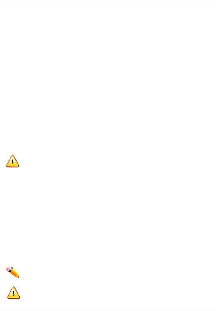
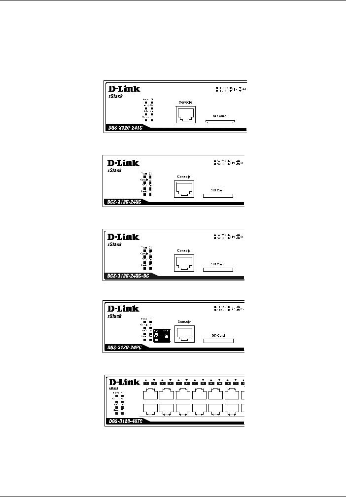
Front Panel Components
The front panel of the Switch consists of LED indicators for Power, Console, RPS, Master, S1, S2, Fan, SD, Stack ID, and for Link/Act for each port on the Switch including SFP port LEDs. A separate table below describes LED indicators in more detail. The DGS-3120-24PC and DGS-3120-48PC switches are equipt with an additional PoE light, to indication whether the ports are running in Power over Ethernet mode.
Figure 1- 1. Front panel view of the DGS-3120-24TC
Figure 1- 2. Front panel view of the DGS-3120-24SC
Figure 1- 3. Front panel view of the DGS-3120-24SC-DC
Figure 1- 4. Front panel view of the DGS-3120-24PC
Figure 1- 5. Front panel view of the DGS-3120-48TC
Figure 1- 6. Front panel view of the DGS-3120-48PC
5
xStack® DGS-3120 Series Managed Switch Hardware Installation Guide
LED Indicators
The Switch front panel presents LED indicators for Power, Console, RPS, Master (stack control), S1, S2, Fan, SD, Stack ID and Link/Act indicators for all ports including the Gigabit Ethernet ports. The DGS-3120-24PC and DGS- 3120-48PC switches are equipt with an additional PoE light, to indication whether the ports are running in Power over Ethernet mode.
Figure 1- 7. LED indicators for the DGS-3120-24TC |
Figure 1- 8. LED indicators for the DGS-3120-24SC |
Figure 1- 9. LED indicators for the DGS-3120-24SC-DC |
Figure 1- 10. LED indicators for the DGS-3120-24PC |
Figure 1- 11. LED indicators for the DGS-3120-48TC |
6

xStack® DGS-3120 Series Managed Switch Hardware Installation Guide
Figure 1- 12. LED indicators for the DGS-3120-48PC |
LED |
Description |
Power |
This LED will light green after powering the Switch on to indicate the ready state of the |
|
device. The indicator is dark when the Switch is no longer receiving power (i.e. powered |
|
off). |
|
|
Console |
This LED will blink green during the Power-On Self Test (POST). When the POST is |
|
finished, the LED goes dark. The indicator will light steady green when a user is logged |
|
in through the console port. |
RPS |
This LED will light green if the Redundant Powers Supply is in use. If the indicator is off, |
|
the RPS is not in use. When the switch detects that the RPS is connected, the light will |
|
be blinking. This LED in not available on the DGS-3120-24SC-DC switch. |
|
|
Master |
For standalone Switches, this will light green. For stacked Switches, a solid Green light |
|
indicates this unit is the Master of the stack. |
S1 |
A solid green stacking port 1 LED indicates there is a secure connection (or link) to an |
|
Ethernet device at any of the ports. The LED blinks green where there is reception or |
|
transmission of data occurring at a port. A darkened LED indicates no link on this |
|
stacking module. |
S2 |
A solid green stacking port 2 LED indicates there is a secure connection (or link) to an |
|
Ethernet device at any of the ports. The LED blinks green where there is reception or |
|
transmission of data occurring at a port. A darkened LED indicates no link on this |
|
stacking module. |
Fan |
This LED blinks red when a fan fails. No light indicates all fans are working normally. |
|
|
SD |
This LED will light green if a Secure Digital (SD) card is plugged in. When the Switch is |
|
reading or writing, the indicator will blink green. No light LED means there is no link. A |
|
solid red LED indicates SD card failure. |
|
|
Stack ID |
For standalone Switches, this will display number “1”. For stacked Switches, this |
|
indicates the position in the stacking box ID. The box ID is assigned either by the user |
|
(static mode) or by the system (automatic mode). When “1” to “6” is displayed, this |
|
indicates the stacking position of the switch. An “H” indicates the device was assigned |
|
as the stacking Master. “h“ means the device was selected to be the Backup Master. A |
|
“G” is displayed when the Safeguard Engine feature enters the exhausted mode. |
|
|
Link/Act LEDs |
The Switch has LED indicators for Link and Activity. The LED will light steady green |
|
when there is a secure connection (or link) to a 1000Mbps Ethernet device at any of the |
|
ports, or steady orange when there is a secure connection (or link) to a 10/100Mbps |
|
Ethernet device at any of the ports. The LED will blink green when a 1000Mbps port is |
|
active, or blink orange when a 10/100Mbps port is active. The LED remains dark when |
|
there is no link or activity. |
PoE |
Only the DGS-3120-24PC and the DGS-3120-48PC switches are equipt with a PoE |
|
LED. When this light is on with a solid green light, it means that the corresponding ports |
|
are feeding power to the PoE devices plugged in. When this light is on with a solid |
|
orange light, it means that the port is in an error condition state. When this light is off, it |
|
means that the ports are not supplying power to the devices plugged into the ports. |
|
|
7
xStack® DGS-3120 Series Managed Switch Hardware Installation Guide
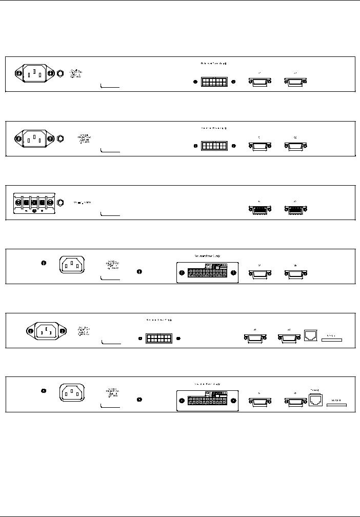
Rear Panel Description
The rear panel contains an AC power connector, an outlet for an external redundant power supply, and two stacking ports.
Figure 1- 13. Rear panel view of the DGS-3120-24TC
Figure 1- 14. Rear panel view of the DGS-3120-24SC
Figure 1- 15. Rear panel view of the DGS-3120-24SC-DC
Figure 1- 16. Rear panel view of the DGS-3120-24PC
Figure 1- 17. Rear panel view of the DGS-3120-48TC
Figure 1- 18. Rear panel view of the DGS-3120-48PC
The AC power connector is a standard three-pronged connector that supports the power cord. Plug-in the female connector of the provided power cord into this socket, and the male side of the cord into a power outlet. The Switch automatically adjusts the power setting to any supply voltage in the range from 100 ~ 240 VAC at 50 ~ 60 Hz. An optional external Redundant Power Supply (DPS-200 for DGS-3120-24TC/SC, DPS-500/DPS-500DC for DGS-3120- 48TC, and DPS-700 for DGS-3120-24PC/48PC) can be plugged into the RPS outlet displayed above. When the internal power fails, this optional external RPS will take over all the power immediately and automatically. There are also two stacking ports on the rear panel. These dedicated stacking ports are specially designed for high speed switch stacking. The Switch supports a stacking cable length of up to 3 meters.
8
Loading...