


DGS-1100-24P
Table of contents
 Loading...
1

DGS-1100 Series Switch Web UI Reference Guide
Information in this document is subject to change without notice.
© 2014 D-Link Corporation. All rights reserved.
Reproduction in any manner whatsoever without the written permission of D-Link Corporation is strictly
forbidden.
Trademarks used in this text: D-Link and the D-Link log o are tr ademark s of D-Link Corporation; Microsoft and
Windows are registered trademarks of Microsoft Corporation.
Other trademarks and trade names may be used in this document to refer to either the entities claiming the
marks and names or their products. D-Link Corporation disclaims any proprietary interest in trademarks and
trade names other than its own.
FCC Warning
This equipment has been tested and found to comply with the limits for a Class A digital device, pursuant to
Part 15 of the FCC Rules. These limits are designed to provide reasonable protection against harmful
interference when the equipment is operated in a commercial environment. This equipment generates, uses,
and can radiate radio frequency energy and, if not installed and used in accordance with this user’s guide, may
cause harmful interference to radio communications. Operation of this equipment in a residential area is likely
to cause harmful interference in which case the user will be required to correct the interference at his own
expense.
CE Mark Warning
This is a Class A product. In a domestic environment, this product may cause radio interference in which case
the user may be required to take adequate measures.
Warnung!
Dies ist ein Produkt der Klasse A. Im Wohnbereich kann dieses Produkt Funkstoerungen verursachen. In
diesem Fall kann vom Benutzer verlangt werden, angemessene Massnahmen zu ergreifen.
Precaución!
Este es un producto de Clase A. En un entorno doméstico, puede causar interferencias de radio, en cuyo case,
puede requerirse al usuario para que adopte las medidas adecuadas.
Attention!
Ceci est un produit de classe A. Dans un environnement domestique, ce produit pourrait causer des
interférences radio, auquel cas l`utilisateur devrait prendre les mesures adéquates.
Attenzione!
Il presente prodotto appartiene alla classe A. Se utilizzato in ambiente domestico il prodotto può causare
interferenze radio, nel cui caso è possibile che l`utente debba assumere provvedimenti adeguati.
VCCI Warning
March, 2014
ii

DGS-1100 Series Switch Web UI Reference Guide
Table of Contents
1. Introduction ................................................................................................................................................................... 1
Audience ............................................................................................................................................................................ 1
Other Documentation ......................................................................................................................................................... 1
Conventions ....................................................................................................................................................................... 1
Notes, Notices, and Cautions ............................................................................................................................................ 2
2. Product Introduction ..................................................................................................................................................... 3
DGS-1100-16 ..................................................................................................................................................................... 3
Front Panel ................................................................................................................................................................... 3
Rear Panel .................................................................................................................................................................... 3
DGS-1100-18 ..................................................................................................................................................................... 4
Front Panel ................................................................................................................................................................... 4
Rear Panel .................................................................................................................................................................... 4
DGS-1100-24 ..................................................................................................................................................................... 5
Front Panel ................................................................................................................................................................... 5
Rear Panel .................................................................................................................................................................... 5
DGS-1100-24P .................................................................................................................................................................. 6
Front Panel ................................................................................................................................................................... 6
Rear Panel .................................................................................................................................................................... 6
DGS-1100-26 ..................................................................................................................................................................... 7
Front Panel ................................................................................................................................................................... 7
Rear Panel .................................................................................................................................................................... 7
3. Hardware Installation .................................................................................................................................................... 8
Step 1: Unpacking .............................................................................................................................................................. 8
Packing contents of DGS-1100-16/18/24/24P/26 ........................................................................................................ 8
Step 2: Switch Installation .................................................................................................................................................. 8
Desktop or Shelf Installation ......................................................................................................................................... 8
Rack Installation ........................................................................................................................................................... 9
Step 3 – Plugging in the AC Power Cord ......................................................................................................................... 10
Power Failure .............................................................................................................................................................. 10
Grounding the Switch ................................................................................................................................................. 10
4. Web-based Switch Configuration .............................................................................................................................. 12
Management Options ....................................................................................................................................................... 12
Connecting using the Web User Interface ....................................................................................................................... 12
Logging onto the Web Manager ...................................................................................................................................... 13
Smart Wizard ................................................................................................................................................................... 14
Web User Interface (Web UI) ........................................................................................................................................... 17
Areas of the User Interface ......................................................................................................................................... 17
5. System .......................................................................................................................................................................... 18
Device Information ........................................................................................................................................................... 18
System Information Settings ............................................................................................................................................ 19
IPv4 Interface ................................................................................................................................................................... 19
IPv6 Interface ................................................................................................................................................................... 20
Port Configuration ............................................................................................................................................................ 20
Port Settings ............................................................................................................................................................... 20
iii

DGS-1100 Series Switch Web UI Reference Guide
Jumbo Frame .............................................................................................................................................................. 21
PoE (DGS-1100-24P Only) .............................................................................................................................................. 23
PoE System ................................................................................................................................................................ 23
PoE Status .................................................................................................................................................................. 24
PoE Configuration ....................................................................................................................................................... 25
System Log ...................................................................................................................................................................... 26
System Log Settings ................................................................................................................................................... 26
System Log Server Settings ....................................................................................................................................... 26
System Log ................................................................................................................................................................. 27
Time ................................................................................................................................................................................. 28
Clock Settings ............................................................................................................................................................. 28
Time Zone Settings ..................................................................................................................................................... 28
SNTP Settings ............................................................................................................................................................ 29
Time Profile ...................................................................................................................................................................... 30
6. Management ................................................................................................................................................................ 31
User Account Settings ..................................................................................................................................................... 31
SNMP ............................................................................................................................................................................... 32
SNMP Global Settings ................................................................................................................................................ 33
SNMP Community Table Settings .............................................................................................................................. 33
SNMP Host Table Settings ......................................................................................................................................... 34
HTTP/HTTPS ................................................................................................................................................................... 35
D-Link Discovery Protocol ................................................................................................................................................ 35
7. Layer 2 Features .......................................................................................................................................................... 36
FDB .................................................................................................................................................................................. 36
Static FDB ................................................................................................................................................................... 36
MAC Address Table Settings...................................................................................................................................... 37
MAC Address Table .................................................................................................................................................... 38
VLAN ................................................................................................................................................................................ 39
802.1Q VLAN .............................................................................................................................................................. 39
Port-based VLAN ........................................................................................................................................................ 39
Management VLAN .................................................................................................................................................... 40
Asymmetric VLAN ....................................................................................................................................................... 40
VLAN Interface ........................................................................................................................................................... 40
Auto Surveillance VLAN ............................................................................................................................................. 43
Voice VLAN................................................................................................................................................................. 45
Spanning Tree ................................................................................................................................................................. 48
STP Global Settings ................................................................................................................................................... 49
STP Port Settings ....................................................................................................................................................... 49
Loopback Detection ......................................................................................................................................................... 50
Link Aggregation .............................................................................................................................................................. 52
L2 Multicast Control ......................................................................................................................................................... 55
IGMP Snooping .......................................................................................................................................................... 55
Multicast Filtering ........................................................................................................................................................ 57
LLDP ................................................................................................................................................................................ 58
LLDP Global Settings ................................................................................................................................................. 58
LLDP Neighbor Port Information ................................................................................................................................ 58
8. Quality of Service (QoS) ............................................................................................................................................. 59
iv

DGS-1100 Series Switch Web UI Reference Guide
802.1p Priority ............................................................................................................................................................. 59
Port Rate Limiting ....................................................................................................................................................... 60
9. Security ........................................................................................................................................................................ 61
Safeguard Engine ............................................................................................................................................................ 61
Safeguard Engine Setti ngs ......................................................................................................................................... 61
Traffic Segmentation Settings .......................................................................................................................................... 62
Storm Control ................................................................................................................................................................... 63
DoS Attack Prevention Settings ....................................................................................................................................... 63
Zone Defense Settings .................................................................................................................................................... 64
SSL .................................................................................................................................................................................. 65
SSL Global Settings .................................................................................................................................................... 65
10. OAM .............................................................................................................................................................................. 66
Cable Diagnostics ............................................................................................................................................................ 66
11. Monitoring .................................................................................................................................................................... 67
Statistics ........................................................................................................................................................................... 67
Port Counters .............................................................................................................................................................. 67
Mirror Settings .................................................................................................................................................................. 68
12. Green ............................................................................................................................................................................ 69
Power Saving ................................................................................................................................................................... 69
EEE .................................................................................................................................................................................. 71
13. Save and Tools ............................................................................................................................................................ 72
Save Configuration .......................................................................................................................................................... 72
Firmware Information ....................................................................................................................................................... 72
Firmware Upgrade & Backup ........................................................................................................................................... 72
Firmware Upgrade from HTTP ................................................................................................................................... 73
Firmware Upgrade from TFTP .................................................................................................................................... 73
Firmware Backup to HTTP ......................................................................................................................................... 73
Firmware Backup to TFTP .......................................................................................................................................... 74
Configuration Restore & Backup ..................................................................................................................................... 75
Configuration Restore from HTTP .............................................................................................................................. 75
Configuration Restore from TFTP .............................................................................................................................. 75
Configuration Backup to HTTP ................................................................................................................................... 76
Configuration Backup to TFTP ................................................................................................................................... 76
Log Backup ...................................................................................................................................................................... 77
Log Backup to HTTP .................................................................................................................................................. 77
Log Backup to TFTP ................................................................................................................................................... 77
Ping .................................................................................................................................................................................. 78
Reset ................................................................................................................................................................................ 78
Reboot System ................................................................................................................................................................ 79
14. Appendix A - Ethernet Technology ........................................................................................................................... 80
Gigabit Ethernet Technology ........................................................................................................................................... 80
Fast Ethernet Technology ................................................................................................................................................ 80
Switching Technology ...................................................................................................................................................... 81
15. Appendix B - Technical Specifications ..................................................................................................................... 82
Hardware Specifications .................................................................................................................................................. 82
Key Components / Performance ................................................................................................................................ 82
v

DGS-1100 Series Switch Web UI Reference Guide
Port Functions ............................................................................................................................................................. 82
Physical & Environment .............................................................................................................................................. 82
Emission (EMI) Certifications...................................................................................................................................... 82
Safety Certifications .................................................................................................................................................... 82
Features ........................................................................................................................................................................... 82
L2 Features ................................................................................................................................................................. 82
L2 Multicasting ............................................................................................................................................................ 82
VLAN ........................................................................................................................................................................... 82
QoS (Quality of Service) ............................................................................................................................................. 83
Security ....................................................................................................................................................................... 83
Management ............................................................................................................................................................... 83
Power Saving .............................................................................................................................................................. 83
16. Appendix C – Rack mount Instructions .................................................................................................................... 84
vi

D-Link DGS-1100 Series Switch User Manual
1. Introduction
This manual’s command descriptions are based on the software release 1.00. The commands listed
here are the subset of commands that are supported by the DGS-1100 Series switch.
Audience
This reference manual is intended for network administrators and other IT networking professionals
responsible for managing the switch by using the Web User Interface (Web UI). The Web UI is the
secondary management interface to the DGS-1100 Series switch, which will be gener ally be referred
to simply as “the Switch” within this manual. This manual is written in a way that assumes that you
already have the experience and knowledge of Ethernet and modern networking principles for Local
Area Networks.
Other Documentation
The documents below are a further source of information in regards to configuring and
troubleshooting the switch. All the documents are available either from the CD, bundled with this
switch, or from the D-Link website. Other documents related to this switch are:
• Getting started Guide
• D-Link Network Assistant (DNA) User Guide
Conventions
Convention Description
Boldface Font
Indicates a button, a toolbar icon, menu, or menu item. For example:
Open the File menu and choose Cancel. Used for emphasis. May
also indicate system messages or prompts appearing on screen.
For example: You have mail. Bold font is also used to represent
filenames, program names and commands. For example: use the
copy command.
Initial capital letter Indicates a window name. Names of keys on the keyboard have
initial capitals. For example: Click Enter.
Menu Name > Menu
Option
Indicates the menu structure. Device > Port > Port Properties
means the Port Properties menu option under the Port menu
option that is located under the Device menu.
Blue Courier Font
This convention is used to represent an example of a screen
console display including example entries of CLI command input
with the corresponding output.
1

D-Link DGS-1100 Series Switch User Manual
Notes, Notices, and Cautions
Below are examples of the three types of indicators used in this manual. When administering your
switch using the information in this document, you should pay special attention to these indicators.
Each example below provides an explanatory remark regarding each type of indicator.
NOTE: A note indicates important information that helps you make better use of
your device.
NOTICE: A notice indicates either potential damage to hardware or loss of data
and tells you how to avoid the problem.
CAUTION: A caution indicates a potential for property damage, personal injury,
or death.
2
2
D-Link DGS-1100 Series Switch User Manual
2. Product Introduction
Thank you and congratulations on your purchase of D-Link DGS-110 0 Ser ies Switch Products.
D-Link's next generation DGS-1100 Series switches blends plug-and-play simplicity with exceptional
value and reliability for small and medium-sized business (SMB) networking. All models are housed
in a new style rack-mount metal case with easy-to-view front panel diagnostic LEDs.
The brand-new DGS-1100 s eries are born to be green by design of IEEE 802.3az Energy Efficient
Ethernet compliant (abbreviated as EEE) and D-Link Green Technologies. It allows significant power
saving during periods of low data activity. In most of use cases and environments, switches are idle
in 90% or more of time. While no traffic in a short period of time, ports on DGS-1100 switch get into
power saving mode automatically. Once if a packet is received, the switch wakes and works
immediately. Connecting to EEE compliant devices, such as PCs and servers, the network can save
energy without compromising any performance. While connecting to legacy devices which do not
support IEEE 802.3az, D-Link Green Technologies can reduce power consumption by changing the
power state of the link.
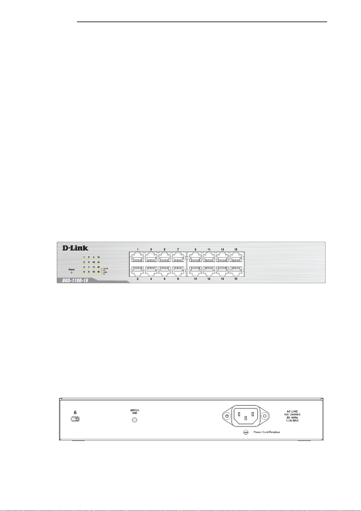
DGS-1100-16
16-Port 10/100/1000Mpbs S witch
Front Panel
Figure 2-1
-
DGS-1100-16 Front Panel
Power LED: The Power LED lights up when the Switch is connected to a power source.
Link/Act/Speed LED (Ports 1-16):
Solid Green: When there is a secure 1000Mbps connection at the port.
Blinking Green or Amber: Indicates that the Switch is either sending or receiving data to the port.
Solid Amber: Indicates that the port is running at 10/100Mbps.
Light off: No link.
Reset: By pressing the Reset butt on until the power LED turns amber, the Switch will change back
to the default configuration and all changes will be lost.
Rear Panel
Figure 2-2 – DGS-1100-16 Rear Panel
Power: The power port is where to connect the AC power cord.
3
3
D-Link DGS-1100 Series Switch User Manual
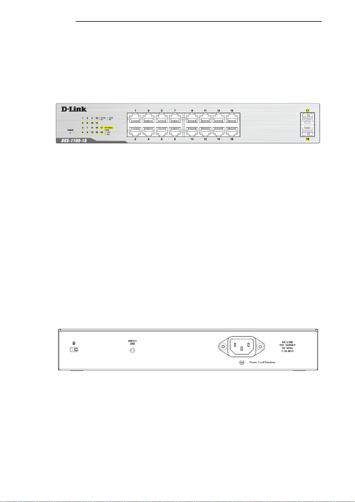
DGS-1100-18
16-Port 10/100/1000Mpbs + 2 Port SFP 1000 Mbps Switch
Front Panel
Figure 2-3
-
DGS-1100-18 Front Panel
Power LED: The Power LED lights up when the Switch is connected to a power source.
Link/Act/Speed LED (Ports 1-16):
Solid Green: When there is a secure 1000Mbps connection at the port.
Blinking Green or Amber: Indicates that the Switch is either sending or receiving data to the port.
Solid Amber: Indicates that the port is running at 10/100Mbps.
Light off: No link.
Link/Act/Speed LED (Ports 17-18):
Solid Green: There is a secure 1000Mbps connection at the port.
Blinking Green: There is reception or transmission occurring at the port.
Light off: No link.
Reset: By pressing the Reset butt on until the power LED turns amber, the Switch will change back
to the default configuration and all changes will be lost.
Rear Panel
Figure 2-4 – DGS-1100-18 Rear Panel
Power: The power port is where to connect the AC power cord.
4
4
D-Link DGS-1100 Series Switch User Manual
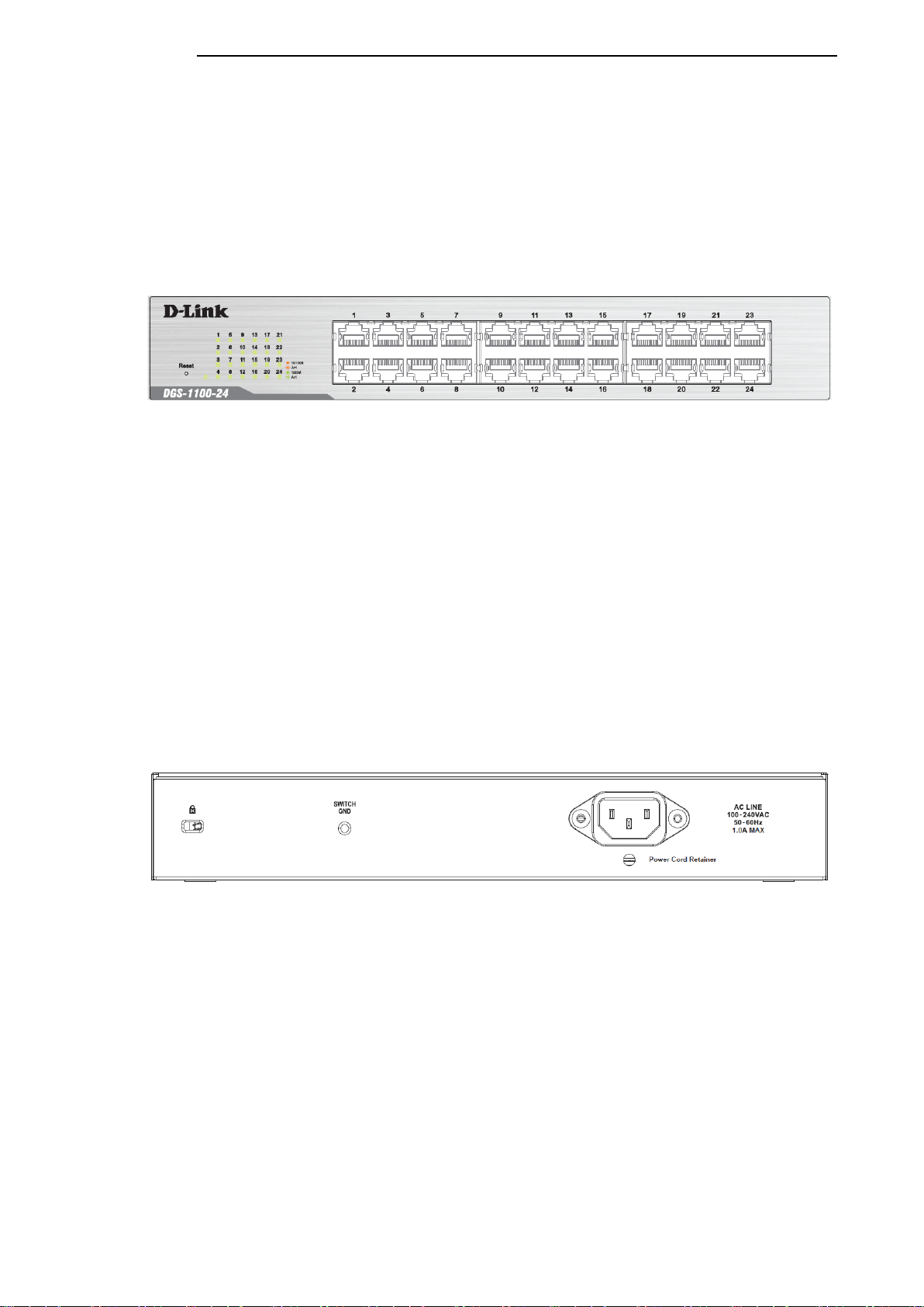
DGS-1100-24
24-Port 10/100/1000Mpbs S witch
Front Panel
Figure 2-5 – DGS-1100-24 Front Panel
Power LED: The Power LED lights up when the Switch is connected to a power source.
Link/Act/Speed LED (Ports 1-24):
Solid Green: When there is a secure 1000Mbps connection at the port.
Blinking Green or Amber: Indicates that the Switch is either sending or receiving data to the port.
Solid Amber: Indicates that the port is running at 10/100 Mbps.
Light off: No link.
Reset: By pressing the Reset butt on until the power LED turns amber, the Switch will change back
to the default configuration and all changes will be lost.
Rear Panel
Figure 2-6 – DGS-1100-24 Rear Panel
Power: Connect the supplied AC power cable to this port.
5
5
D-Link DGS-1100 Series Switch User Manual
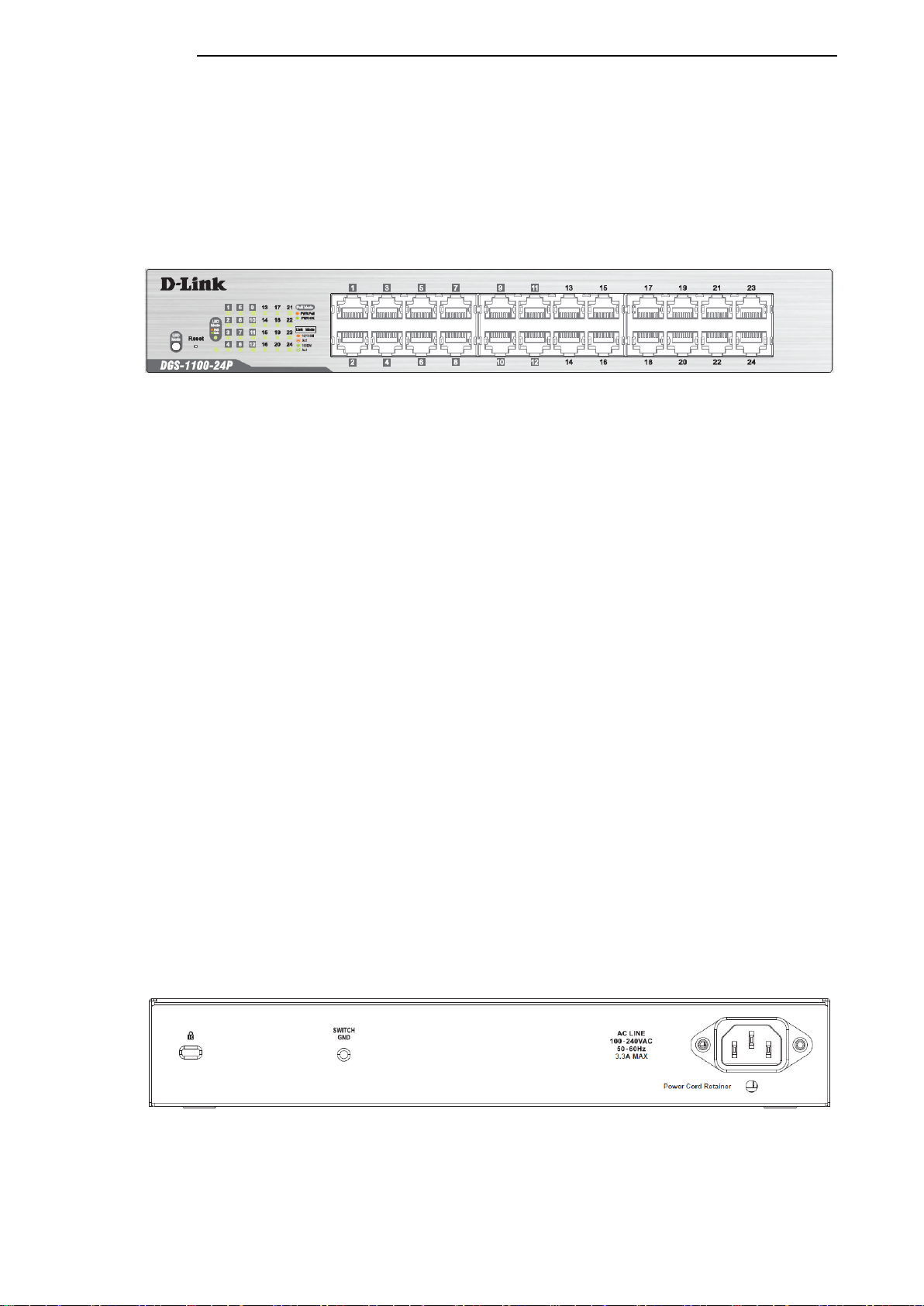
DGS-1100-24P
24-Port 10/100/1000Mpbs PoE Switch
Front Panel
Figure 2-7 – DGS-1100-24P Front Panel
Power LED: The Power LED lights up when the Switch is connected to a power source.
Link/Act/Speed LED (Ports 1-24):
Solid Green: When there is a secure 1000Mbps connection at the port.
Blinking Green or Amber: Indicates that the Switch is either sending or receiving data to the port.
Solid Amber: Indicates that the port is running at 10/100Mbps.
Light off: No link.
PoE Mode (Ports 1-12):
Green: Indicates that PoE mode is active.
Amber: Indicates that there is an issue with the PoE mode activating properly.
Light off: Indicates that PoE mode is not active.
LED Mode Button: Pressing this button will change the LED behavior from Link mode, and PoE
Mode
Reset: By pressing the Reset butt on until the power LED turns amber, the Switch will change back
to the default configuration and all changes will be lost.
Note: The LED behavior for ports 1-12 will switch between Link mode and PoE mode when the PoE
mode is active.
Rear Panel
Figure 2-8 – DGS-1100-24P Rear Panel
Power: Connect the supplied AC power cable to this port.
6
6
D-Link DGS-1100 Series Switch User Manual
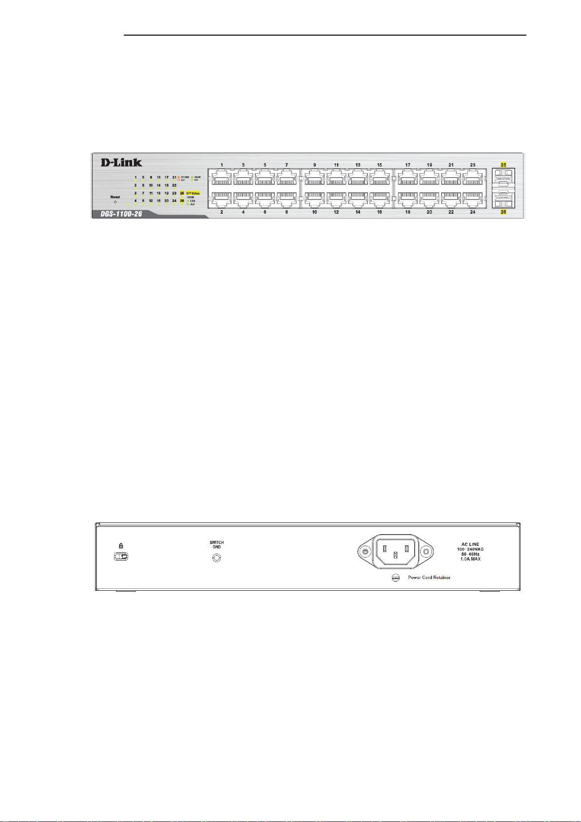
DGS-1100-26
24-Port 10/100/1000Mpbs + 2 Port SFP 1000 Mbps Switch
Front Panel
Figure 2-9 – DGS-1100-26 Front Panel
Power LED: The Power LED lights up when the Switch is connected to a power source.
Link/Act/Speed LED (Ports 1-24):
Solid Green: When there is a secure 1000Mbps connection at the port.
Blinking Green or Amber: Indicates that the Switch is either sending or receiving data to the port.
Solid Amber: Indicates that the port is running at 10/100Mbps.
Light off: No link.
Link/Act/Speed LED (Ports 25-26):
Solid Green: There is a secure 1000Mbps connection at the port.
Blinking Green: There is reception or transmission occurring at the port.
Light off: No link.
Reset: By pressing the Reset butt on until the power LED turns amber, the Switch will change back
to the default configuration and all changes will be lost.
Rear Panel
Figure 2-10 – DGS-1100-26 Rear Panel
Power: Connect the supplied AC power cable to this port.
7
7

D-Link DGS-1100 Series Switch User Manual
3. Hardware Installation
This chapter provides unpacking and installation information for the D-Link Switch.
Step 1: Unpacking
Open the shipping carton and carefully unpack its contents. Please consult the packing list located in
the User Manual to make sure all items are present and undamaged. If any item is missing or
damaged, please contact your local D-Link reseller for replacement.
Packing contents of DGS-1100-16/18/24/24P/26
• One D-Link DGS-1100 Series Switch
• One AC power cord
• Four rubber feet
• Screws and two mounting brackets
• One accessory kit for a ground screw
• One Multi-lingual Getting Started Guide
• One CD with User Manual
If any item is found missing or damaged, please contact the local reseller for replacement.
Step 2: Switch Installation
For safe switch installation and operation, it is recommended that you:
• Visually inspect the power cord to see that it is secured fully to the AC power connector.
• Make sure that there is proper heat dissipation and adequate ventilation around the switch.
• Do not place heavy objects on the switch.
Desktop or Shelf Installation
When installing the switch on a desktop or shelf, the rubber feet included with the device must be
attached on the bottom at each corner of the device’s base. Allow enough ventilation space between
the device and the objects around it.
Figure 3-1 – Attach the adhesive rubber pads to the bottom
8
8
D-Link DGS-1100 Series Switch User Manual
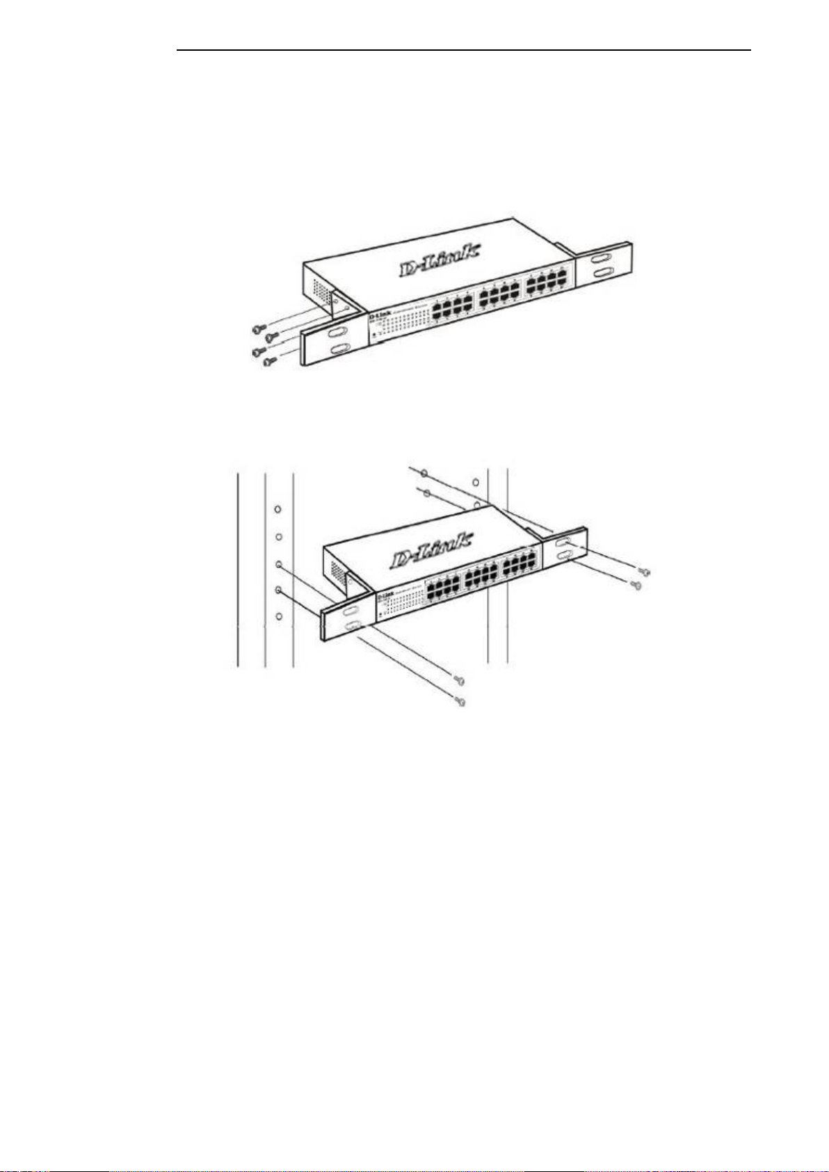
Rack Installation
The switch can be mounted in an EIA standard size 11-inch rack, which can be placed in a wiring
closet with other equipment . To install, attach the mounting brackets to the switch’s side panels (one
on each side) and secure them with the screws provided (please note that these brackets are not
designed for palm size switches).
Figure 3-2 – Attach the mounting brackets to the Switch
Then, use the screws provided with the equipment rack to mount the switch in the rack.
Figure 3-3 – Mount the Switch in the rack or chassis
Please be aware of following safety Instructions when installing:
A) Elevated Operating Ambient - If installed in a closed or multi-unit rack assembly, the operating
ambient temperature of the rack environment may be greater than room ambient. Therefore,
consideration should be given to installing the equipment in an environment compatible with the
maximum ambient temperature (Tma) specified by the manufacturer.
B) Reduced Air Flow - Installation of the equipment in a rack should be such that the amount of air
flow required for safe operation of the equipment is not compromised.
C) Mechanical Loading - Mounting of the equipment in the rack should be such that a hazardous
condition is not achieved due to uneven mechanical loading.
D) Circuit Overloading - Consideration should be given to the connection of the equipment to the
supply circuit and the effect that overloading of the circuits might have on overcurrent protection and
supply wiring. Appropriate consideration of equipment nameplate ratings should be used when
addressing this concern.
E) Reliable Earthing - Reliable earthing of rack-mounted equipment should be maintained. Particular
attention should be given to supply connections other than direct connections to the branch circuit
(e.g. use of power strips)."
9
9
D-Link DGS-1100 Series Switch User Manual
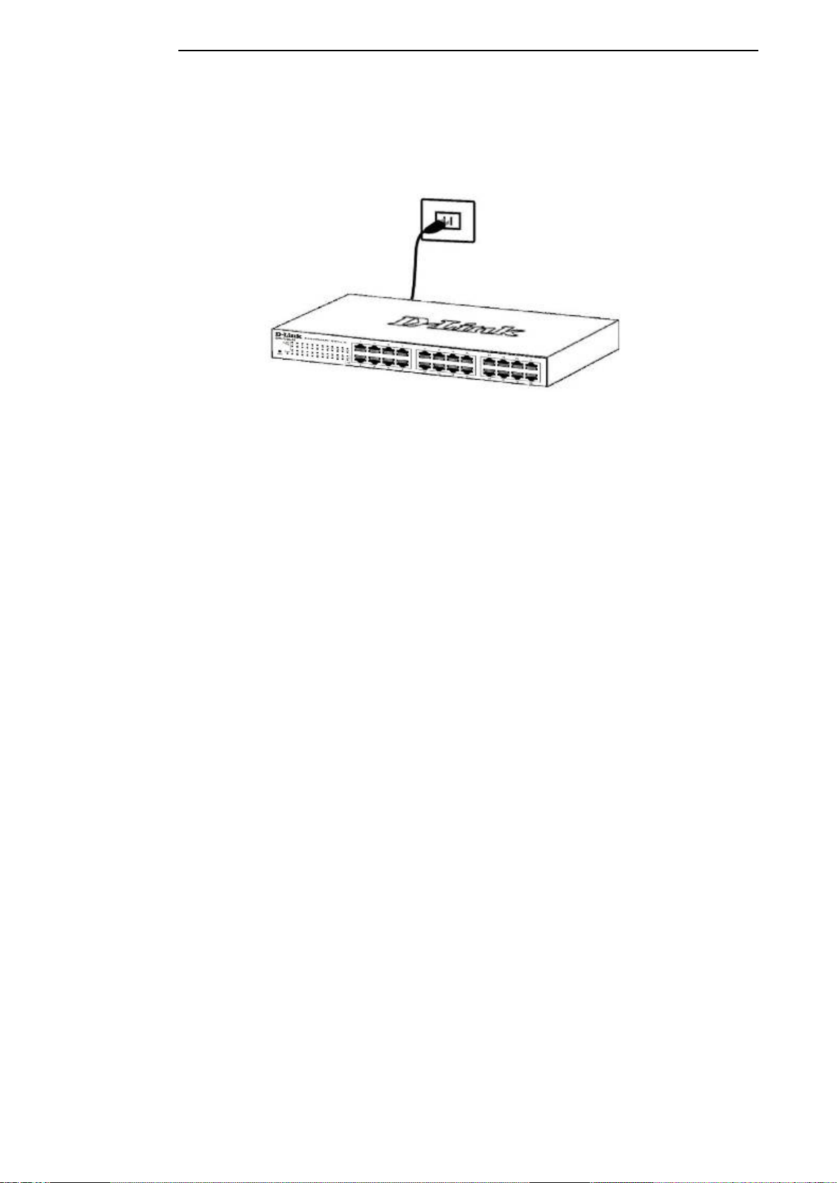
Step 3 – Plugging in the AC Power Cord
Users may now connect the AC power cord into the rear of the switch and to an electrical outlet
(preferably one that is grounded and surge protected).
Figure 3-4 – Plugging the switch into an outlet
Power Failure
As a precaution, the switch should be unplugged in case of power failure. When power is resumed,
plug the switch back in.
Grounding the Switch
This section describes how to connect the DGS-1100 Series Switch to ground. You must complete
this procedure before powering your switch.
Required Tools and Equipment
• Ground screws (included in the accessory kit): One M4 x 6 mm (metric) pan-head screw
• Ground cable (not included in the accessory kit): The grounding cable should be sized
according to local and national installation requirements. Depending on the power supply
and system, a 12 to 6 AWG copper conductor is required for U.S installation. Commercially
available 6 AWG wire is recommended. The length of the cable depends on the proximity of
the switch to proper grounding facilities.
• A screwdriver (not included in the accessory kit)
The following steps let you connect the switch to a protective ground:
Step 1: Verify if the system power is off.
Step 2: Use the ground cable to place the #8 terminal lug ring on top of the ground-screw opening,
as seen in the figure below.
Step 3: Insert the ground screw into the ground-screw opening.
Step 4: Using a screwdriver, tighten the ground screw to secure the ground cable to the switch.
Step 5: Attach the terminal lug ring at the other end of the grounding cable to an appropriate
grounding stud or bolt on rack where the switch is installed.
Step 6: Verify if the connections at the ground connector on the switch and the rack are securely
attached.
1
1
0
0

D-Link DGS-1100 Series Switch User Manual
Figure 3-5 – Ground cable, screw and #8 terminal lug rings
1
1
1
1

D-Link DGS-1100 Series Switch User Manual
4. Web-based Switch Configuration
Management Options
Connecting using the Web User Interface
Logging onto the Web Manager
Smart Wizard
Web User Interface (Web UI)
Management Options
The Switch provides multiple access platforms that can be used to configure, manage and monitor
networking features available on the Switch. Currently there are three management platforms
available and they are described below.
Web-based Management Interface
After successfully installing the Switch, the user can configure the Switch, monitor the LED panel,
and display statistics graphically using a Web browser, such as Microsoft® Internet Explorer, Opera
Firefox, Safari, or Google Chrome.
SNMP-based Management
The Switch can be managed with an SNMP-compatible console program. The Switch supports
SNMP version 1.0, and version 2c. The SNMP agent decodes the incoming SNMP messages and
responds to requests with MIB objects stored in the database. The SNMP agent updates the MIB
objects to generate statistics and counters.
D-Link Network Assistant
DNA (D-Link Network Assistant) included on the installation CD is a program for discovering DGS-
1100 Series Switches with the same L2 network segment connected to your PC. This tool can
support windows 2000, XP, Vista, and Windows 7.
Connecting using the Web User Interface
Most software functions of the DGS-1100 Series switches can be managed, configured and
monitored via the embedded web-based (HTML) interface. Manage the Switch from remote stations
anywhere on the network through a standard web browser. The web browser acts as a universal
access tool and can communicate directly with the Switch using the HTTP or HTTPS protocol.
You need the following equipment to begin the web configuration of your device:
• A PC with a RJ-45 Ethernet connection
• A standard Ethernet cable
Figure 4-1 – Connecting to a DGS-1100 Series Switch
Connect the Ethernet cable to any of the ports on the front panel of the switch and to the Ethernet
port on the PC.
1
1
2
2
D-Link DGS-1100 Series Switch User Manual
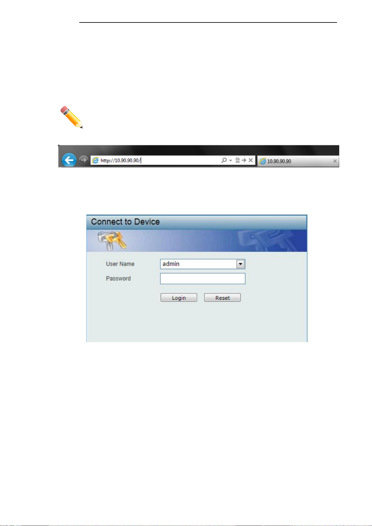
Logging onto the Web Manager
To access the Web User Interface, simply open a standard web browser on the management PC
and enter the Switch’s default IP address into the address bar of the browser and press the Enter
key.
NOTE: The default IP address of this switch is 10.90.90.90, with a subnet mask
of 255.0.0.0.
Figure 4-2 Displays entering the IP address in Internet Explorer
This will open the user authenticatio n wind o w, as seen bel o w.
Figure 4-3 User Authentication window
By default, the username is “admin” and the password is also “admin”. Click the Login button.
1
1
3
3
D-Link DGS-1100 Series Switch User Manual
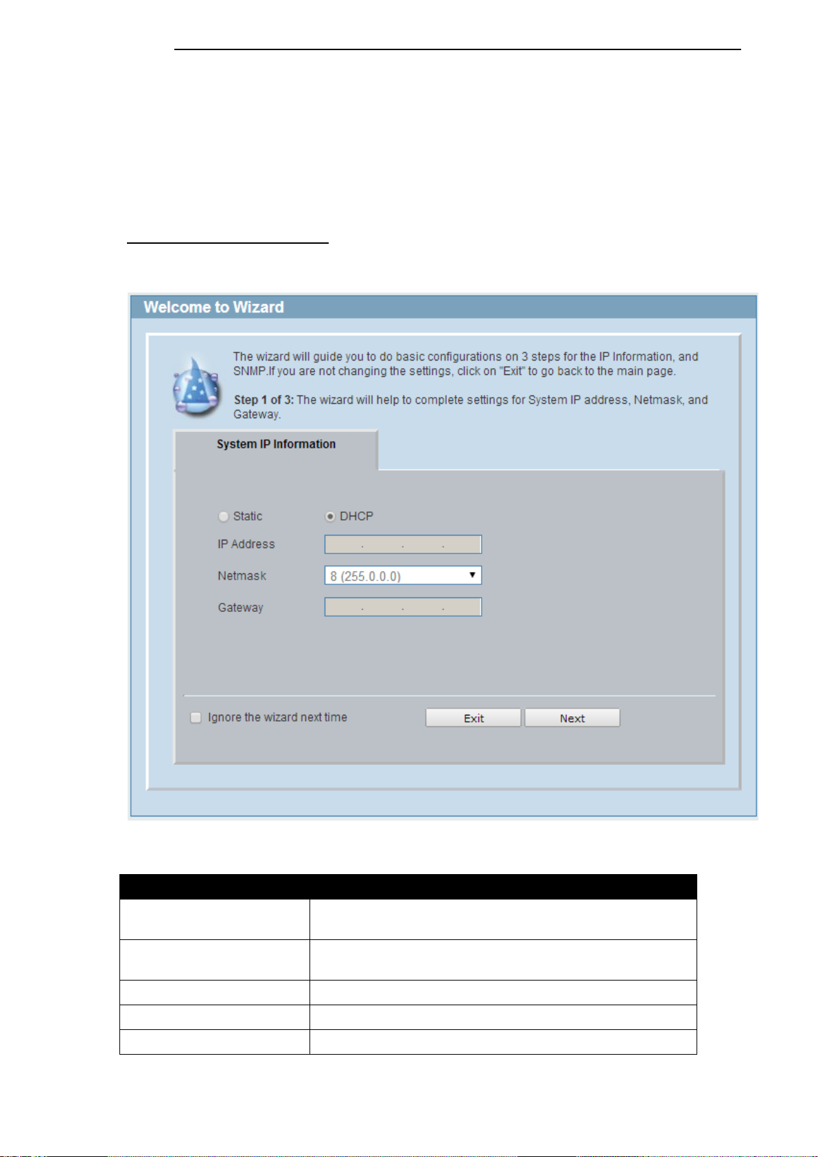
Smart Wizard
After a successfully connecting to the Web User Interface for the first time, the Smart Wizard
embedded Web utility will be launched. This wizard will guide the user through basic configuration
steps that is essential for first time connection to the Switch.
Step 1 – System IP Information
In this window, the user can configure the IP address assignment method, the static IP address,
Netmask and Gateway address.
Figure 4-4 System IP Information window
The fields that can be configured are described below:
Parameter Description
Static
Select this option to manually configure and use IP address
settings on this switch.
DHCP
Select this option to obtain IP address settings from a DHCP
server.
IP Address
Enter the IP address of the Switch here.
Netmask
Select the Netmask option here.
Gateway
Enter the default gateway IP address here.
1
1
4
4
D-Link DGS-1100 Series Switch User Manual
Tick the Ignore the wizard next time option to skip the Smart Wizard on the next login.
Click the Exit button to discard the changes made, exit the Smart Wizard, and continue to the Web
UI.
Click the Next button to accept the changes made and continue to the next step.
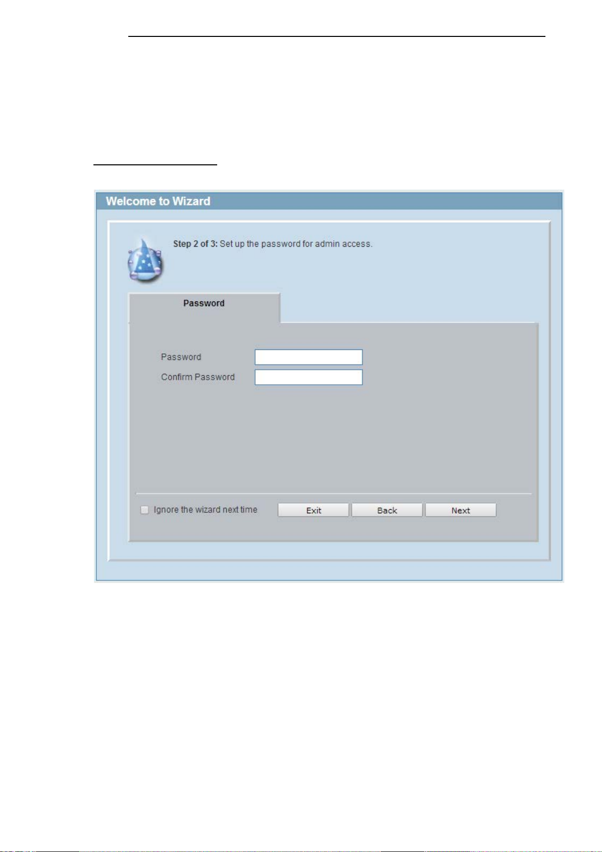
Step 2 – Admin Password
In this window, the user can set the password used with the admin account.
Figure 4-5 Admin Password
Tick the Ignore the wizard next time option to skip the Smart Wizard on the next login.
Click the Exit button to discard the changes made, exit the Smart Wizard, and continue to the Web
UI.
Click the Next button to accept the changes made and continue to the next step.
1
1
5
5
D-Link DGS-1100 Series Switch User Manual
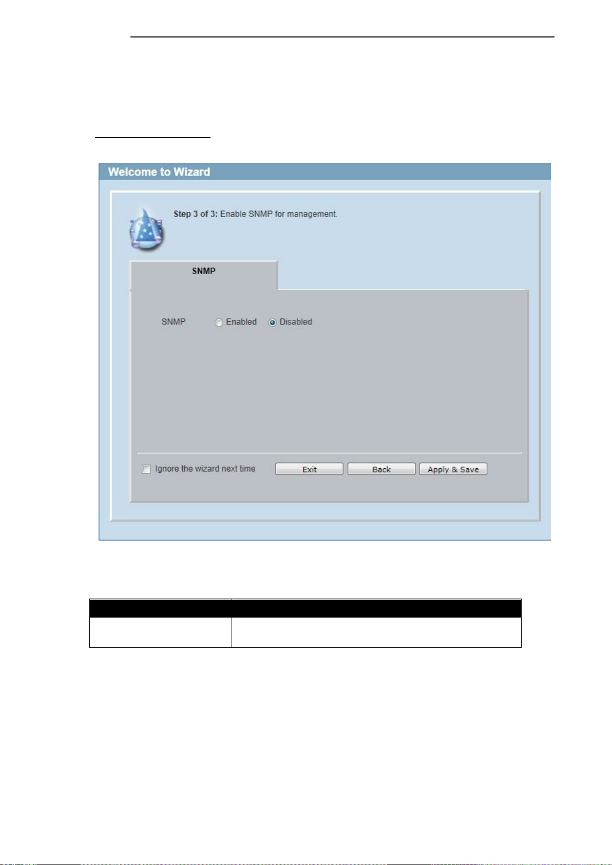
Step 3 – SNMP Settings
In this window, the user can enable or disable the SNMP function.
Figure 4-6 SNMP window
The fields that can be configured are described below:
Parameter Description
SNMP Select the Enabled option to enable the SNMP function.
Select the Disabled option to disable the SNMP function.
Tick the Ignore the wizard next time option to skip the Smart Wizard on the next login.
Click the Exit button to discard the changes made, exit the Smart Wizard, and continue to the Web
UI.
Click the Apply & Save button to accept the changes made, and then continue to the Web UI.
1
1
6
6

D-Link DGS-1100 Series Switch User Manual
Web User Interface (Web UI)
By clicking the Exit button in the Smart Wizard, you will enter the Web-based Management interface.
Areas of the User Interface
The figure below shows the user interface. Three distinct areas that divide the user interface, as
described in the table.
Figure 4-7 Main Web UI window
Area Number Description
AREA 1
In this area, a folder tree layout is displayed of functions that
can be configured using the Web UI. Open folders and click
the hyperlinked menu buttons to access each individual page
for configuration. The DGS-1100-24 link is the default page
that will display basic monitoring settings for this switch.
AREA 2
In this area, the Switch’s configuration page can be found,
based on the selection made in Area 1.
AREA 1
AREA 2
1
1
7
7
D-Link DGS-1100 Series Switch User Manual
5. System
Device Information
System Information Setting
IPv4 Interface
IPv6 Interface
PoE (DGS-1100-24P Only)
System Log
Time
Time Profile
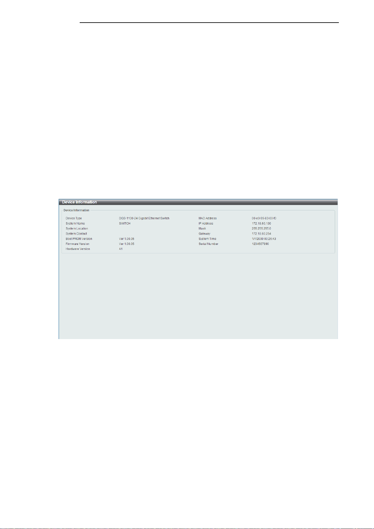
Device Information
In this window, the Device Information, CPU, and Used status are displayed. It appears
automatically when you log in the Switch. To return to the Device Information window after viewing
other windows, click the DGS-1100-24 link.
Figure 5-1 Device Information window
1
1
8
8
D-Link DGS-1100 Series Switch User Manual
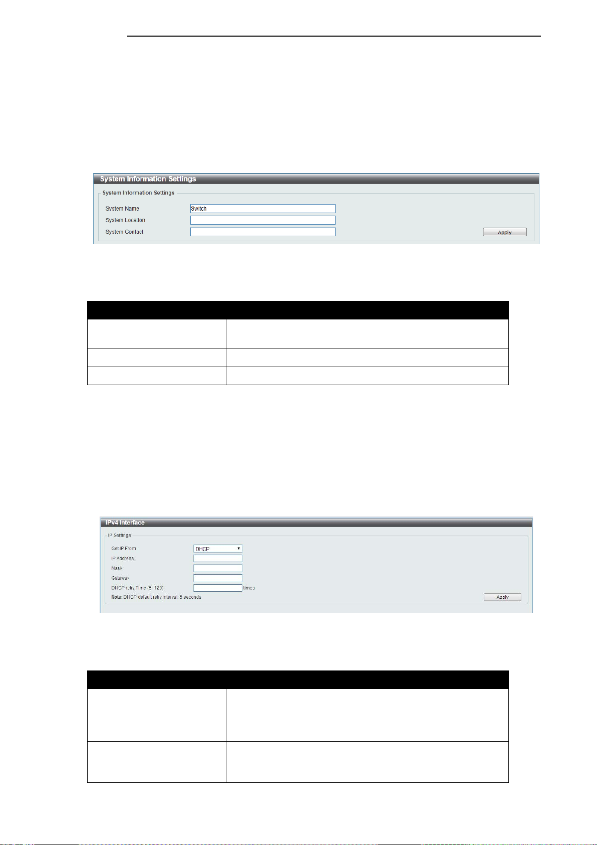
System Information Settings
The user can enter a System Name, System Location, and System Contact to aid in defining the
Switch.
To view the following window, click System > System Information Settings, as shown below:
Figure 5-2 System Information Settings window
The fields that can be configured are described below:
Parameter Description
System Name
Enter a system name for the Switch, if so desired. This name
will identify it in the Switch network.
System Location
Enter the location of the Switch, if so desired.
System Contact
Enter a contact name for the Switch, if so desired.
Click the Apply button to accept the changes made.
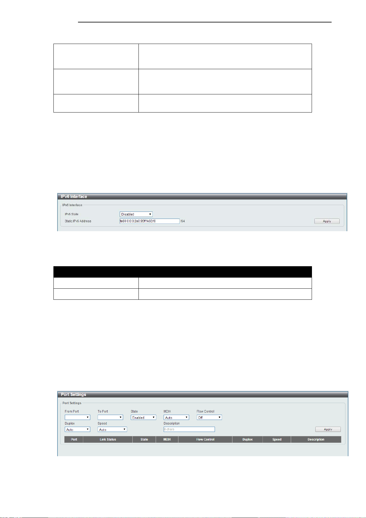
IPv4 Interface
This window is used to configure the IPv4 settings of the switch.
To view the following window, click System > System Information Settings > IPv4 Interface, as
shown below:
Figure 5-3 Peripheral Settings window
The fields that can be configured are described below:
Parameter Description
Get IP From
Select DHCP to automatically obtain an IP address. Select
Static to manually configure the IP address settings. BOOTP
allows the switch to get an IP configuration using the BOOTP
protocol.
IP Address
If Static is selected, enter the IP address of the switch. If
DHCP or BOOTP is selected, the automatically obtained IP
address will be displayed.
1
1
9
9
D-Link DGS-1100 Series Switch User Manual
Mask
If Static is selected, enter the IP address of the switch. If
DHCP or BOOTP is selected, the automatically obtained
network mask will be displayed.
Gateway
If Static is selected, enter the IP address of the switch. If
DHCP or BOOTP is selected, the automatically obtained
gateway will be displayed.
DHCP retry Time
If DHCP is selected, enter the number of times to retry
obtaining an IP address.
Click the Apply button to accept the changes made.
IPv6 Interface
This window is used to configure the IPv6 settings of the switch.
To view the following window, click System > System Information Settings > IPv6 Interface, as
shown below:
Figure 5-4 Peripheral Settings window
The fields that can be configured are described below:
Parameter Description
IPv6 State Select whether to Enable or Disable IPv6 functionality.
Static IPv6 Address
If enabled, enter the static IPv6 address of the switch.
Click the Apply button to accept the changes made.
Port Configuration
Port Settings
This window is used to view and configure the Switch’s port settings.
To view the following window, click System > Port Configuration > Port Settings, as shown below:
Figure 5-5 Port Settings window
2
2
0
0

D-Link DGS-1100 Series Switch User Manual
The fields that can be configured are described below:
Parameter Description
From Port / To Port
Select the appropriate port range used for the configuration
here.
State Select this option to enable or disable the physical port
here.
MDIX
Select the Medium Dependent Interface Crossover (MDIX)
option here. Options to choose from are Auto, Normal, and
Cross.
Auto - Select this option for auto-sensing of the optimal type
of cabling.
Normal - Select this option for normal cabling. If this option
is selected, the port is in the MDIX mode and can be
connected to a PC’s NIC using a straight-through cable or a
port (in the MDIX mode) on another switch through a cross-
over cable.
Cross - Select this option for cross cabling. If this option is
selected, the port is in the MDI mode and can be connected
to a port (in the MDIX mode) on another switch through a
straight cable.
Flow Control Select to either turn flow control On or Off here. Ports
configured for full-duplex use 802.3x flow control, half-duplex
ports use back-pressure flow control, and Auto ports use an
automatic selection of the two.
Duplex
Select the duplex mode used here. Options to choose from
are Auto, Half, and Full.
Speed
Select the port speed option here. This option will manually
force the connected on the selected port to only connect at
the speed specified here. Options to choose from are Auto,
10M, 100M. 1000M speed is only available when Auto is
selected.
Description
Enter a 8 characters description for the corresponding port
here.
Click the Apply button to accept the changes made.
Note: The fiber ports on the DGS-1100-18 and DGS-1100-26 only support Auto for duplex and
speed. Also, the fiber ports on the DGS-1100-18 and DGS-1100-26 do not support MDIX.
Jumbo Frame
This window is used to view and configure the Jumbo Frame size and settings. The Switch supports
jumbo frames. Jumbo frames are Ethernet frames with more than 1,518 bytes of payload. The
Switch supports jumbo frames with a maximum frame size of up to 9216 bytes.
To view the following window, click System > Port Configuration > Jumbo Frame, as shown below:
2
2
1
1
Loading...