


Daikin FTD20JEVLK, RD20JEVLK, FTD25JEVLK, RD25JEVLK, FTYD20JEVLK Installation manuals
...INSTALLATION
MANUAL
R22 SPLIT SERIES
Installation Manual
R22 Split Series English
MODELS
FTD20JEVLK RD20JEVLK
FTD25JEVLK RD25JEVLK
FTYD20JEVLK RYD20JEVLK
FTYD25JEVLK RYD25JEVLK
IM-WMJ-0211(0)-DAIKIN (SASO)
Part No.: R08019036068

OUTLINE AND DIMENSIONS
Indoor Unit
THE MARK |
SHOWS PIPING DIRECTION |
REAR |
REAR |
LEFT |
RIGHT |
|
TOP VIEW |
C |
|
|
A |
|
|
|
|
|
|
|
|
|
NAME PLATE |
|
|
SIGNAL |
B |
|
|
RECEIVER |
|
|
|
|
|
|
|
|
TERMINAL |
|
|
|
BLOCK |
BOTTOM |
BOTTOM |
SIDE VIEW |
WITH EARTH |
TERMINAL |
|||
|
LOUVER |
INDOOR UNIT |
|
|
FRONT GRILLE FIXED SCREWS |
ON/OFF SWITCH |
|
|
(INSIDE) |
ROOM TEMPERATURE |
|
|
|
|
|
|
FRONT VIEW |
THERMISTOR (INSIDE) |
|
All dimensions are in mm
Recommended mounting plate retention spots |
|
|
|
|
|
|
|
|
|
|||||
(7 spots in all) |
|
|
|
|
|
|
|
|
|
|
|
|
|
|
|
D |
|
|
|
|
|
|
|
|
E |
|
|
|
|
| <![if ! IE]> <![endif]>F |
|
|
|
|
|
|
|
|
|
|
|
<![if ! IE]> <![endif]>F |
|
|
| <![if ! IE]> <![endif]>B |
|
|
|
|
|
|
|
|
|
|
|
|
|
|
|
|
|
|
|
|
|
|
|
|
|
|
Through the wall |
||
|
|
|
|
|
|
|
|
|
|
|
|
hole Ø 65mm |
|
|
| <![if ! IE]> <![endif]>G |
|
|
|
|
|
|
|
|
|
|
|
<![if ! IE]> <![endif]>G |
|
|
H |
J |
|
Liquid pipe end |
M |
Gas pipe end |
|
|
K |
I |
Drain hose position |
||||
|
|
L |
|
A |
|
|
|
|
|
|
|
|
||
|
|
|
|
|
|
|
|
|
|
|
|
|
|
|
|
|
|
|
INSTALLATION PLATE FT(Y)D20/25JEVLK |
|
|
|
|
|
|||||
|
|
|
|
|
|
|
|
|
|
|
All dimensions are in mm |
|||
Dimension |
A |
B |
C |
D |
E |
F |
G |
H |
I |
J |
K |
L |
M |
|
Model |
|
|||||||||||||
|
|
|
|
|
|
|
|
|
|
|
|
|
|
|
FT(Y)D20/25JEVLK |
1065 |
310 |
228 |
190 |
173 |
61 |
40 |
45 |
48 |
91 |
219 |
580 |
45 |
|
|
|
|
|
|
|
1-1 |
|
|
|
|
|
|
|
|
<![endif]>Original Instruction English

Outdoor Unit
L |
K |
L |
|
|
|
|
<![if ! IE]> <![endif]>N |
|
|
|
<![if ! IE]> <![endif]>M |
|
|
|
<![if ! IE]> <![endif]>C |
|
|
<![if ! IE]> <![endif]>P |
<![if ! IE]> <![endif]>N |
|
A |
|
|
O |
D |
|
|
<![endif]>Q
<![if ! IE]><![endif]>B
| <![if ! IE]> <![endif]>T |
| <![if ! IE]> <![endif]>S |
<![endif]>R
All dimensions are in mm
C |
|
G |
H |
| <![if ! IE]> <![endif]>F |
|
| <![if ! IE]> <![endif]>E |
|
I |
J |
Dimension |
A |
B |
C |
D |
E |
F |
G |
H |
I |
J |
K |
L |
M |
N |
O |
|
Model |
||||||||||||||||
|
|
|
|
|
|
|
|
|
|
|
|
|
|
|
||
|
|
|
|
|
|
|
|
|
|
|
|
|
|
|
|
|
R(Y)D20JEVLK |
855 |
628 |
328 |
508 |
181 |
44 |
93 |
149 |
101 |
113 |
603 |
126 |
164 |
17 |
49 |
|
|
|
|
|
|
|
|
|
|
|
|
|
|
|
|
|
|
R(Y)D25JEVLK |
855 |
730 |
328 |
520 |
182 |
44 |
93 |
149 |
101 |
113 |
603 |
126 |
164 |
17 |
34 |
|
|
|
|
|
|
|
|
|
|
|
|
|
|
|
|
|
|
|
|
|
|
|
|
|
|
|
|
|
|
|
|
|
|
|
Dimension |
P |
Q |
R |
S |
T |
|
|
|
|
|
|
|
|
|
|
|
Model |
|
|
|
|
|
|
|
|
|
|
||||||
|
|
|
|
|
|
|
|
|
|
|
|
|
|
|
||
|
|
|
|
|
|
|
|
|
|
|
|
|
|
|
|
|
R(Y)D20JEVLK |
32 |
3 |
23 |
73 |
75 |
|
|
|
|
|
|
|
|
|
|
|
|
|
|
|
|
|
|
|
|
|
|
|
|
|
|
|
|
R(Y)D25JEVLK |
32 |
3 |
23 |
73 |
75 |
|
|
|
|
|
|
|
|
|
|
|
|
|
|
|
|
|
|
|
|
|
|
|
|
|
|
|
1-2

INSTALLATION MANUAL
This manual provides the procedures of installation to ensure a safe and good standard of operation for the air conditioner unit.
Special adjustment may be necessary to suit local requirement.
Before using your air conditioner, please read this instruction manual carefully and keep it for future reference.
SAFETY PRECAUTIONS
!WARNING
•Installation and maintenance should be performed by qualiÀed persons who are familiar with local code and regulation, and experienced with this type of appliance.
•All Àeld wiring must be installed in accordance with the national wiring regulation.
•Ensure that the rated voltage of the unit corresponds to that of the name plate before commencing wiring work according to the wiring diagram.
•The unit must be GROUNDED to prevent possible hazard due to insulation failure.
•All electrical wiring must not touch the water piping or any moving parts of the fan motors.
•Confirm that the unit has been switched OFF before installing or servicing the unit.
•Risk of electric shock, can cause injury or death. Disconnect all remain electric power supplies before servicing.
•DO NOT pull out the power cord when the power is ON. This may cause serious electrical shocks which may result in the Àre hazards.
•Keep the indoor and outdoor units, power cable and transmission wiring, at least 1m from TVs and radios, to prevent distorted pictures and static. {Depending on the type and source of the electrical waves, static may be heard even when more than 1m away}.
! CAUTION
Please take note of the following important points when installing.
•Do not install the unit where leakage of Áammable gas may occur.
If gas leaks and accumulates around the unit, it may cause Àre ignition.
•Ensure that drainage piping is connected properly.
If the drainage piping is not connected properly, it may cause water leakage which will dampen the furniture.
•Do not overcharge the unit.
This unit is factory pre-charged. Overcharge will cause over-current or damage to the compressor.
•Ensure that the unit·s panel is closed after service or installation.
Unsecured panels will cause the unit to operate noisily.
•Sharp edges and coil surfaces are potential locations which may cause injury hazards. Avoid from being in contact with these places.
•Before turning off the power supply set the remote controller·s ON/OFF switch to the “OFF” position to preventthenuisancetrippingoftheunit.Ifthisisnotdone, the unit·s fans will start turning automatically when power resumes, posing a hazard to service personnel or the user.
•Do not install the units at or near doorway.
•Do not operate any heating apparatus too close to the air conditionerunitoruseinroomwheremineraloil,oilvapour or oil steam exist, this may cause plastic part to melt or deform as a result of excessive heat or chemical reaction.
•When the unit is used in kitchen, keep Áour away from going into suction of the unit.
•This unit is not suitable forfactory used where cutting oil mist or iron powder exist or voltage Áuctuates greatly.
•Do not install the units at area like hot spring or oil reÀnery plant where sulphide gas exists.
•Ensure the color of wires of the outdoor unit and the terminal markings are same to the indoors respectively.
•IMPORTANT: DO NOTINSTALLOR USETHEAIR CONDITIONER UNIT IN A LAUNDRY ROOM.
•Don·t use joined and twisted wires for incoming power supply.
•The equipment is not intended for use in a potentially explosive atmosphere.
NOTICE
Disposal requirement
Your air conditioning product is marked with this symbol. This means that electrical and electronic products shall not be mixed with unsorted household waste.
Do not try to dismantle the system yourself: the dismantling of the air conditioning system, treatment of the refrigerant, of oil and of other parts must be done by a qualiÀed installer in accordance with relevant local and national legislation. Air conditioners must be treated at a specialized treatment facility for re-use, recycling and recovery. By ensuring this product is disposed of correctly, you will help to prevent potential negative consequences for the environment and human health. Please contact the installer or local authority for more information.
Batteries must be removed from the remote controller and disposed of separately in accordance with relevant local and national legislation.
<![endif]>English
1-3

IMPORTANT
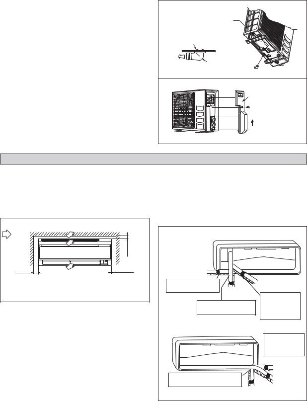
Unpacking Procedures
• Wall Mounted Unit
1. After takeoff the bands and pull out one side cushion, push the unit to the opposite side.
2. Pull out the unit from the other side.
• Outdoor Unit
1. After takeoff the bands, pull out the carton box from the top side of the unit.
* This product is not designed for re-packing. In case of re-packing, contact to Daikin Dealer.
1-4

INSTALLATION DIAGRAM
Indoor unit
Front panel
50mm or more from walls (on both sides)
M4 x 12L
Air Àlter
Air-Purifying Filter with bacteriostatic virustatic function (2)
Air-Purifying Filter Air Àlter with bacteriostatic  virustatic function
Filter frame 
 Tab
Tab 


Outdoor Unit
30mm or more from ceiling
Service lid
ΘOpening service lid
Service lid is opening/ closing type.
ΘOpening method
1)Remove the service lid screws.
2)Pull out the service lid diagonally down in the direction of the arrow.
3)Pull down.
|
|
Cut thermal insulation pipe |
||
Caulk pipe |
to an appropriate length and |
|||
wrap it with tape, making |
||||
hole gap |
||||
sure that no gap is left in the |
||||
with putty. |
||||
insulation pipe·s cut line. |
||||
|
|
|||
|
|
|
Wrap the insulation pipe with |
|
|
|
|
the Ànishing tape from bottom |
|
|
|
|
to top. |
|
|
|
|
||
|
|
|
|
|
250mm |
from wall |
<![endif]>English
INSTALLATION OF THE OUTDOOR UNIT
The outdoor unit must be installed in such a way, so as to prevent short circuit of the hot discharged air or obstruction to the smooth air Áow. Please follow the installation clearances shown in the Àgure. Select the coolest possible place where intake air temperature is not greater than the outside air temperature (please refer operating range).
Installation clearances
Dimension |
A |
B |
C |
D |
|
|
|
|
|
Minimum Distance, |
300 |
1000 |
300 |
500 |
mm (in) |
(11.8) |
(39.4) |
(11.8) |
(19.7) |
Note: If there is any obstacle higher than 2m, or if there is any obstruction at the upper part of the unit, please allow more space than the Àgure indicated in the above table.
|
|
A |
B |
|
|
|
<![if ! IE]> <![endif]>Obstacle |
<![if ! IE]> <![endif]>Return air |
<![if ! IE]> <![endif]>Discharge air |
<![if ! IE]> <![endif]>Obstacle |
|
|
C |
|
|
D |
|
| <![if ! IE]> <![endif]>Obstacle |
<![if ! IE]> <![endif]>Return air |
|
|
<![if ! IE]> <![endif]>Service access |
<![if ! IE]> <![endif]>Obstacle |
1-5
Condensed Water Disposal Of Outdoor Unit
(Heat Pump Unit Only)
•There are 2 holes on the base of Outdoor Unit for condensed water to Áow out. Insert the drain elbow to one of the holes.
•To install the drain elbow, Àrst insert one portion of the hook to the base (portion A), then pull the drain elbow in the direction shown by the arrow while inserting the other portion to the base. After installation, check to ensure that the drain elbow clings to base Àrmly.
•If the unit is installed in a snowy and chilly area, condensed water may freeze in the base. In such case, please remove plug at the bottom of unit to smooth the drainage.
PLUG |
A |
BASE |
DRAIN ELBOW |
DRAIN ELBOW |
Please remove |
side plate when |
connecting the piping |
and connecting cord |
PUSH & PULL UP |
INSTALLATION OF THE INDOOR UNIT
The indoor unit must be installed in such a way so as to prevent short circuit of the cool discharged air with the hot return air. Please follow the installation clearance shown in the Àgure. Do not place the indoor unit where there could be direct sunlight shining on it. Also, this location must be suitable for piping and drainage, and be away from doors or windows.
Air Áow |
|
<![if ! IE]> <![endif]>min. 30 (Space for performance) |
|
(Indoor) |
|
||
|
|
||
min. 50 |
Required space |
min. 50 |
|
(Space for |
(Space for |
||
|
|||
maintenance) |
|
maintenance) |
|
|
|
All dimensions are in mm |
The refrigerant piping can be routed to the unit in a number of ways (left or right from the back of the unit), by using the cutout holes on the casing of the unit (see Àgure). Bend the pipes carefully to the required position in order to align it with the holes. For the side and bottom, hold the bottom of the piping and then position it to the required direction (see Àgure). The condensation drain hose can be taped to the pipes.
Right-side, right-back or right-bottom piping
Right-side |
|
|
|
piping |
|
|
|
Remove pipe port cover |
|
Right-back piping |
|
|
|
||
here for right-side piping |
Right-bottom |
|
|
|
|
||
|
piping |
Bind coolant pipe |
|
|
|
||
Remove pipe port cover |
and drain hose |
||
together with |
|||
here for right-bottom piping |
|||
insulating tape. |
|||
|
|
||
Left-side, left-back or left-bottom piping
|
|
Remove pipe port |
|
|
cover here for |
|
|
left-side piping |
|
|
Left-side |
|
|
piping |
Remove pipe port cover here for |
Left-back |
|
left-bottom piping |
|
|
|
piping |
|
|
|
|
|
Left-bottom piping |
|
1-6
 Loading...