


Daikin FTKB12AXVJURKB12AXVJU, FTKB18AXVJURKB18AXVJU, FTXB24AXVJURXB24AXVJU, FTXB12AXVJURXB12AXVJU, FTXB18AXVJURXB18AXVJU User Manual
...SERVICE MANUAL
Inverter Wall Mounted Single Split
MODELS
Cooling Only
FTKB09AXVJU RKB09AXVJU
FTKB12AXVJU RKB12AXVJU
FTKB18AXVJU RKB18AXVJU
FTKB24AXVJU RKB24AXVJU
FTKN09AXVJU RKN09AXVJU
FTKN12AXVJU RKN12AXVJU
FTKN18AXVJU RKN18AXVJU
FTKN24AXVJU RKN24AXVJU
Heatpump
FTXB09AXVJU RXB09AXVJU
FTXB12AXVJU RXB12AXVJU
FTXB18AXVJU RXB18AXVJU
FTXB24AXVJU RXB24AXVJU
FTXN09AXVJU RXN09AXVJU
FTXN12AXVJU RXN12AXVJU
FTXN18AXVJU RXN18AXVJU
FTXN24AXVJU RXN24AXVJU
SM-5WM-Y-NA-B1
|
|
|
Table of Contents |
Table of Contents |
|
||
1.0 Inverter Single Split...................................................................................................... |
1 |
||
1.1 |
Product line-up......................................................................................................... |
1 |
|
1.2 |
Printed Circuit board (PCB) connector wiring diagram............................................ |
3 |
|
1.3 |
Piping Length & Elevation...................................................................................... |
10 |
|
1.4 |
Outline & Dimension.............................................................................................. |
11 |
|
1.5 |
Engineering Data................................................................................................... |
15 |
|
2.0 Function & Control...................................................................................................... |
17 |
||
2.1 Temperature Control............................................................................................... |
17 |
||
2.2 |
Cooling and Heating Mode Operation.................................................................... |
17 |
|
2.3 |
Dry Mode................................................................................................................ |
18 |
|
2.4 Fan Mode............................................................................................................... |
19 |
||
2.5 Auto Mode.............................................................................................................. |
19 |
||
2.6 |
Cold Draft Prevention............................................................................................. |
19 |
|
2.7 |
Sleep Mode............................................................................................................ |
20 |
|
2.8 |
Quiet Function........................................................................................................ |
20 |
|
2.9 Eco+ Function......................................................................................................... |
20 |
||
2.10 Powerful Function................................................................................................. |
21 |
||
2.11 Indoor - Outdoor Communication......................................................................... |
21 |
||
2.12 Thermistors in RK(X)B,RK(X)N ........................................................................... |
22 |
||
2.13 |
Minimum Off Time Control.................................................................................... |
23 |
|
2.14 Auto Restart......................................................................................................... |
23 |
||
2.15 Auto Random Restart........................................................................................... |
23 |
||
2.16 |
Four Way Valve Control....................................................................................... |
24 |
|
2.17 |
Outdoor Fan Control............................................................................................ |
24 |
|
2.18 |
Rotation Regulating Functions............................................................................. |
25 |
|
2.19 |
Defrost Cycle........................................................................................................ |
26 |
|
2.20 |
Indoor Coil Freeze Prevention............................................................................. |
27 |
|
2.21 |
High Pressure Protection..................................................................................... |
27 |
|
2.22 |
Discharge Pipe Temperature Control................................................................... |
28 |
|
2.23 |
Overall Current Control........................................................................................ |
28 |
|
2.24 |
Overall Frequency Control................................................................................... |
29 |
|
3.0 Service Diagnosis....................................................................................................... |
31 |
||
3.1 |
Error Indication from Indoor................................................................................... |
31 |
|
3.2 Error Code retrieved by handset............................................................................. |
33 |
||
3.3 |
Error code description for Inverter.......................................................................... |
34 |
|
|
|
|
|

|
|
Table of Contents |
4.0 |
Wiring Connection...................................................................................................... |
61 |
5.0 |
Refrigerant Diagram.................................................................................................... |
65 |
6.0 Appendix A................................................................................................................... |
67 |
|
ii
Table of Contents
Safety Cautions
Caution and warnings
•Be sure to read the following safety cautions before conducting repair work.
•The caution items are classified into “ Warning” and “
 Caution”. The “
 Warning” items are especially important since they can lead to death or serious injury if they are not followed closely. The
“ Caution” items can also lead to serious accidents under some conditions if they are not followed. Therefore, be sure to observe all the safety caution items described below.
•About the pictograms
 This symbol indicates an item for which caution must be exercised.
The pictogram shows the item to which attention must be paid.
 This symbol indicates a prohibited action.
The prohibited item or action is shown inside or near the symbol.
 This symbol indicates an action that must be taken, or an instruction.
The instruction is shown inside or near the symbol.
•After the repair work is complete, be sure to conduct a test operation to ensure that the equipment operates normally, and explain the cautions for operating the product to the customer.
Caution in Repair
 Warning
Be sure to disconnect the power cable plug from the plug socket before disassembling the equipment for a repair.
Working on the equipment that is connected to a power supply can cause an electrical shock.
If it is necessary to supply power to the equipment to conduct the repair or inspecting the circuits, do not touch any electrically charged sections of the equipment.
If the refrigerant gas discharges during the repair work, do not touch the discharging refrigerant gas.
The refrigerant gas can cause frostbite.
When disconnecting the suction or discharge pipe of the compressor at the welded section, release the refrigerant gas completely at a well-ventilated place first.
If there is a gas remaining inside the compressor, the refrigerant gas or refrigerating machine oil discharges when the pipe is disconnected, and it can cause injury.
If the refrigerant gas leaks during the repair work, ventilate the area. The refrigerant gas can generate toxic gases when it contacts flames.
The step-up capacitor supplies high-voltage electricity to the electrical components of the outdoor unit.
Be sure to discharge the capacitor completely before conducting repair work. A charged capacitor can cause an electrical shock.
Do not start or stop the air conditioner operation by plugging or unplugging the power cable plug.
Plugging or unplugging the power cable plug to operate the equipment can cause an electrical shock or fire.
Table of Contents
 Caution
Do not repair the electrical components with wet hands.
Working on the equipment with wet hands can cause an electrical shock.
Do not clean the air conditioner by splashing water.
Washing the unit with water can cause an electrical shock.
Be sure to provide the grounding when repairing the equipment in a humid or wet place, to avoid electrical shocks.
Be sure to turn off the power switch and unplug the power cable when cleaning the equipment.
The internal fan rotates at a high speed, and cause injury.
Do not tilt the unit when removing it.
The water inside the unit can spill and wet the furniture and floor.
Be sure to check that the refrigerating cycle section has cooled down sufficiently before conducting repair work.
Working on the unit when the refrigerating cycle section is hot can cause burns.
Use the welder in a well-ventilated place.
Using the welder in an enclosed room can cause oxygen deficiency.
iv
Table of Contents
Cautions Regarding Products after Repair
 Warning
Be sure to use parts listed in the service parts list of the applicable model and appropriate |
|
tools to conduct repair work. Never attempt to modify the equipment. |
|
The use of inappropriate parts or tools can cause an electrical shock, excessive heat |
|
generation or fire. |
|
|
|
When relocating the equipment, make sure that the new installation site has sufficient |
|
strength to withstand the weight of the equipment. |
|
If the installation site does not have sufficient strength and if the installation work is not |
|
conducted securely, the equipment can fall and cause injury. |
|
Be sure to install the product correctly by using the provided standard installation frame. |
For integral |
Incorrect use of the installation frame and improper installation can cause the equipment |
units only |
to fall, resulting in injury. |
|
|
|
Be sure to install the product securely in the installation frame mounted on a window |
For integral |
frame. |
units only |
If the unit is not securely mounted, it can fall and cause injury. |
|
|
|
Be sure to use an exclusive power circuit for the equipment, and follow the technical |
|
standards related to the electrical equipment, the internal wiring regulations and the |
|
instruction manual for installation when conducting electrical work. |
|
Insufficient power circuit capacity and improper electrical work can cause an electrical |
|
shock or fire. |
|
|
|
Be sure to use the specified cable to connect between the indoor and outdoor units. Make |
|
the connections securely and route the cable properly so that there is no force pulling the |
|
cable at the connection terminals. |
|
Improper connections can cause excessive heat generation or fire. |
|
|
|
When connecting the cable between the indoor and outdoor units, make sure that the |
|
terminal cover does not lift off or dismount because of the cable. |
|
If the cover is not mounted properly, the terminal connection section can cause an |
|
electrical shock, excessive heat generation or fire. |
|
Do not damage or modify the power cable. |
|
Damaged or modified power cable can cause an electrical shock or fire. |
|
Placing heavy items on the power cable, and heating or pulling the power cable can |
|
damage the cable. |
|
Do not mix air or gas other than the specified refrigerant (R-410A) in the refrigerant |
|
system. |
|
If air enters the refrigerating system, an excessively high pressure results, causing |
|
equipment damage and injury. |
|
|
|
If the refrigerant gas leaks, be sure to locate the leak and repair it before charging the |
|
refrigerant. After charging refrigerant, make sure that there is no refrigerant leak. |
|
If the leak cannot be located and the repair work must be stopped, be sure to perform |
|
pump-down and close the service valve, to prevent the refrigerant gas from leaking into |
|
the room. The refrigerant gas itself is harmless, but it can generate toxic gases when it |
|
contacts flames, such as fan and other heaters, stoves and ranges. |
|
|
|
When replacing the coin battery in the remote controller, be sure to disposed of the old |
|
battery to prevent children from swallowing it. |
|
If a child swallows the coin battery, see a doctor immediately. |
|
|
|
Table of Contents
 Caution
Installation of a leakage breaker is necessary in some cases depending on the conditions of the installation site, to prevent electrical shocks.
Do not install the equipment in a place where there is a possibility of combustible gas leaks.
If a combustible gas leaks and remains around the unit, it can cause a fire.
Be sure to install the packing and seal on the installation frame properly.
If the packing and seal are not installed properly, water can enter the room and wet the furniture and floor.
Inspection after Repair
 Warning
Check to make sure that the power cable plug is not dirty or loose, then insert the plug into a power outlet all the way.
If the plug has dust or loose connection, it can cause an electrical shock or fire.
If the power cable and lead wires have scratches or deteriorated, be sure to replace them.
Damaged cable and wires can cause an electrical shock,excessive heat generation or fire.
Do not use a joined power cable or extension cable, or share the same power outlet with other electrical appliances, since it can cause an electrical shock, excessive heat generation or fire.
 Caution
Check to see if the parts and wires are mounted and connected properly, and if the connections at the soldered or crimped terminals are secure.
Improper installation and connections can cause excessive heat generation, fire or an electrical shock.
If the installation platform or frame has corroded, replace it.
Corroded installation platform or frame can cause the unit to fall, resulting in injury.
Check the grounding, and repair it if the equipment is not properly grounded. Improper grounding can cause an electrical shock.
Be sure to measure the insulation resistance after the repair, and make sure that the resistance is 1 Mohm or higher.
Faulty insulation can cause an electrical shock.
Be sure to check the drainage of the indoor unit after the repair.
Faulty drainage can cause the water to enter the room and wet the furniture and floor.
vi

Inverter Single Split
1.0Inverter Single Split
1.1Product line-up
1.1.1 Indoor Unit
|
|
|
|
|
|
|
|
Classification |
|
|
|
|
|
|
|
|
|||
Nomenclature |
|
|
RemoteController |
|
|
|
|
PCB |
|
|
|
AirPurification |
|
Marking |
Others |
||||
|
|
|
|
|
|
|
|
|
|
|
|
|
|
|
|
|
|
|
|
|
|
|
|
|
|
|
|
|
|
|
|
|
|
|
|
|
|
|
|
|
BRC52A61 |
BRC52A62 |
|
BRC52B63 |
BRC52B64 |
W_2_03C |
W_2_03D |
W_2_03E |
|
W_2_03E_M |
W_2_04A |
W_2_04B |
Saranet Filter |
|
Titanium Apatite |
UL |
|
CE |
Auto Restart |
|
|
|
|
|
|
|
|
|
|
|
|
|
|
|
|
|
|
|
|
FTKB09/12AXVJU |
|
|
|
|
X |
|
|
|
|
X |
|
|
X |
|
X |
X |
|
|
X |
|
|
|
|
|
|
|
|
|
|
|
|
|
|
|
|
|
|
|
|
FTKN09/12AXVJU |
|
X |
|
|
|
|
|
|
|
X |
|
|
X |
|
|
X |
|
|
X |
|
|
|
|
|
|
|
|
|
|
|
|
|
|
|
|
|
|
|
|
FTKB18/24AXVJU |
|
|
|
|
X |
|
|
|
|
|
|
X |
X |
|
X |
X |
|
|
X |
|
|
|
|
|
|
|
|
|
|
|
|
|
|
|
|
|
|
|
|
FTKN18/24AXVJU |
|
X |
|
|
|
|
|
|
|
|
|
X |
X |
|
|
X |
|
|
X |
|
|
|
|
|
|
|
|
|
|
|
|
|
|
|
|
|
|
|
|
FTXB09/12AXVJU |
|
|
|
X |
|
|
|
|
|
X |
|
|
X |
|
X |
X |
|
|
X |
|
|
|
|
|
|
|
|
|
|
|
|
|
|
|
|
|
|
|
|
FTXN09/12AXVJU |
X |
|
|
|
|
|
|
|
|
X |
|
|
X |
|
|
X |
|
|
X |
|
|
|
|
|
|
|
|
|
|
|
|
|
|
|
|
|
|
|
|
FTXB18/24AXVJU |
|
|
|
X |
|
|
|
|
|
|
|
X |
X |
|
X |
X |
|
|
X |
|
|
|
|
|
|
|
|
|
|
|
|
|
|
|
|
|
|
|
|
FTXN18/24AXVJU |
X |
|
|
|
|
|
|
|
|
|
|
X |
X |
|
|
X |
|
|
X |
|
|
|
|
|
|
|
|
|
|
|
|
|
|
|
|
|
|
|
|
1

Inverter Single Split
1.1.2 Outdoor Unit
|
|
|
|
|
Classification |
|
|
|
|
|
||||
Nomenclature |
|
PCB |
|
Refrigerant Control |
|
|
Fin |
|
Compressor |
|
Marking |
Others |
||
|
|
|
|
|
|
|
|
|
|
|
|
|
|
|
|
Main PCB (ADGPA34) |
Main PCB (Y364) |
Filter PCB (YV62) |
EXV |
|
Hydrophilic (Blue) |
|
Hydrophilic (Gold) |
|
DC Inverter Swing |
UL |
|
CE |
Drain Elbow |
|
|
|
|
|
|
|
|
|
|
|
|
|
|
|
RKB09/12AXVJU |
X |
|
|
X |
|
X |
|
|
|
X |
X |
|
|
|
|
|
|
|
|
|
|
|
|
|
|
|
|
|
|
RKN09/12AXVJU |
X |
|
|
X |
|
X |
|
|
|
X |
X |
|
|
|
|
|
|
|
|
|
|
|
|
|
|
|
|
|
|
RKB18/24AXVJU |
|
X |
X |
X |
|
X |
|
|
|
X |
X |
|
|
|
|
|
|
|
|
|
|
|
|
|
|
|
|
|
|
RKN18/24AXVJU |
|
X |
X |
X |
|
X |
|
|
|
X |
X |
|
|
|
|
|
|
|
|
|
|
|
|
|
|
|
|
|
|
RXB09/12AXVJU |
X |
|
|
X |
|
X |
|
|
|
X |
X |
|
|
X |
|
|
|
|
|
|
|
|
|
|
|
|
|
|
|
RXN09/12AXVJU |
X |
|
|
X |
|
X |
|
|
|
X |
X |
|
|
X |
|
|
|
|
|
|
|
|
|
|
|
|
|
|
|
RXB18/24AXVJU |
|
X |
X |
X |
|
X |
|
|
|
X |
X |
|
|
X |
|
|
|
|
|
|
|
|
|
|
|
|
|
|
|
RXN18/24AXVJU |
|
X |
X |
X |
|
X |
|
|
|
X |
X |
|
|
X |
|
|
|
|
|
|
|
|
|
|
|
|
|
|
|
2
Inverter Single Split
1.2 Printed Circuit Board (PCB) connector wiring diagram
1.2.1 Indoor PCB: FTKB09/12AXVJU, FTKN09/12AXVJU, FTXB09/12AXVJU, FTXN09/12AXVJU
1.2.1.1 Main PCB: W_2_03D ; W_2_03E ; W_2_03E_M
Item |
Indication on PCB |
Description |
|
|
|
1 |
A1 |
Connector for fan motor |
|
|
|
2 |
A2 |
Connector for swing motor |
|
|
|
3 |
A3 |
Connector for fan motor feedback |
|
|
|
4 |
A4 |
Fuse |
|
|
|
5 |
A5 |
Varistor |
|
|
|
6 |
A6 |
Connector for wired controller |
|
|
|
7 |
A7 |
Connector for signal receiver PCB |
|
|
|
8 |
A8 |
Connector for heat exchanger thermistor |
|
|
|
A1 A2 A3
A5 |
A4 |
|
A7
A6
A8
3
Inverter Single Split
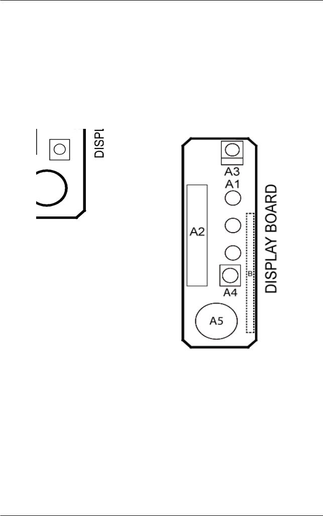
1.2.1.2 Signal board
Item |
Indication on PCB |
Description |
|
|
|
1 |
A1 |
Operational LED |
|
|
|
2 |
A2 |
Connector for Control PCB |
|
|
|
3 |
A3 |
Remote controller signal receiver |
|
|
|
4 |
A4 |
Operation ON/OFF switch |
|
|
|
5 |
A5 |
Buzzer |
|
|
|
A1
A3
A2
A4
A5
Applicable Model : |
Applicable Model : |
FTKB09/12AXVJU |
FTKN09/12AXVJU |
FTXB09/12AXVJU |
FTXN09/12AXVJU |
4
Inverter Single Split
1.2.2 Indoor PCB: FTKB18/24AXVJU, FTKN18/24AXVJU, FTXB18/24AXVJU,
FTXN18/24AXVJU
1.2.2.1 Main PCB: W_2_04A ; W_2_04B
|
|
Item |
Indication on PCB |
Description |
|
|||
|
|
|
|
|
|
|
|
|
|
1 |
A1 |
Connector for fan motor |
|
||||
|
|
|
|
|
|
|
|
|
|
2 |
A2 |
Connector for swing motor |
|
||||
|
|
|
|
|
|
|
|
|
|
3 |
A3 |
Connector for fan motor feedback |
|
||||
|
|
|
|
|
|
|
|
|
|
4 |
A4 |
Fuse |
|
||||
|
|
|
|
|
|
|
|
|
|
5 |
A5 |
Varistor |
|
||||
|
|
|
|
|
|
|
|
|
|
6 |
A6 |
Connector for wired controller |
|
||||
|
|
|
|
|
|
|
|
|
|
7 |
A7 |
Connector for signal receiver PCB |
|
||||
|
|
|
|
|
|
|
|
|
|
|
|
|
|
|
|
|
|
|
|
|
|
|
|
|
|
|
|
|
|
|
|
|
|
|
|
|
|
|
|
|
|
|
|
|
|
|
|
|
|
|
|
|
|
|
|
|
|
|
|
|
|
|
|
|
|
|
|
|
|
|
|
|
|
|
|
|
|
|
|
|
|
|
|
|
|
|
|
|
|
|
|
|
|
|
|
|
|
|
5
Inverter Single Split
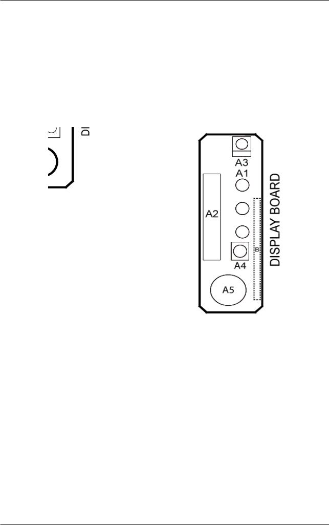
1.2.2.2 Signal board
Item |
Indication on PCB |
Description |
|
|
|
1 |
A1 |
Operational LED |
|
|
|
2 |
A2 |
Connector for Control PCB |
|
|
|
3 |
A3 |
Remote controller signal receiver |
|
|
|
4 |
A4 |
Operation ON/OFF switch |
|
|
|
5 |
A5 |
Buzzer |
|
|
|
A1
A3
A2
A4
A5
Applicable Model : |
Applicable Model : |
FTKB18/24AXVJU |
FTKN18/24AXVJU |
FTXB18/24AXVJU |
FTXN18/24AXVJU |
6
Inverter Single Split
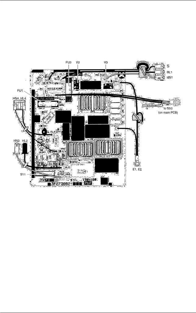
1.2.3 Outdoor PCB: RKB09/12AXVJU, RKN09/12AXVJU, RXB09/12AXVJU, RXN09/12AXVJU
1.2.3.1 Main PCB
Item |
Indication on PCB |
Description |
|
|
|
1 |
S11 |
Connector for S10 on main PCB |
|
|
|
2 |
HL1, HN1, S |
Connector for terminal board |
|
|
|
3 |
E1, E2 |
Terminal for earth wire |
|
|
|
4 |
HL2, HN2 |
Connector for HL3 HN3 on main PCB |
|
|
|
5 |
HL4, HN4 |
Connector for S12 on main PCB |
|
|
|
6 |
FU1 |
Fuse (3.15A, 250V) |
|
|
|
7 |
FU3 |
Fuse (30A, 250V) |
|
|
|
8 |
V2, V3 |
Varistor |
|
|
|
7
Inverter Single Split
1.2.4 Outdoor PCB: RKB18/24AXVJU, RKN18/24AXVJU, RXB18/24AXVJU, RXN18/24AXVJU
1.2.4.1 Filter PCB
Item |
Indication on PCB |
Description |
|
|
|
1 |
S11 |
Connector for indoor PCB |
|
|
|
2 |
FU3 |
Fuse (20A) |
|
|
|
3 |
V2, V3 |
Varistor |
|
|
|
8

Inverter Single Split
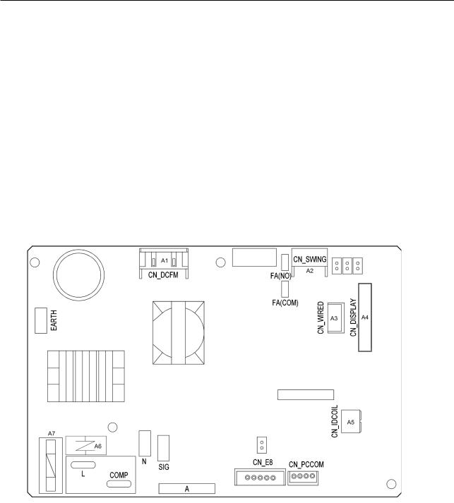
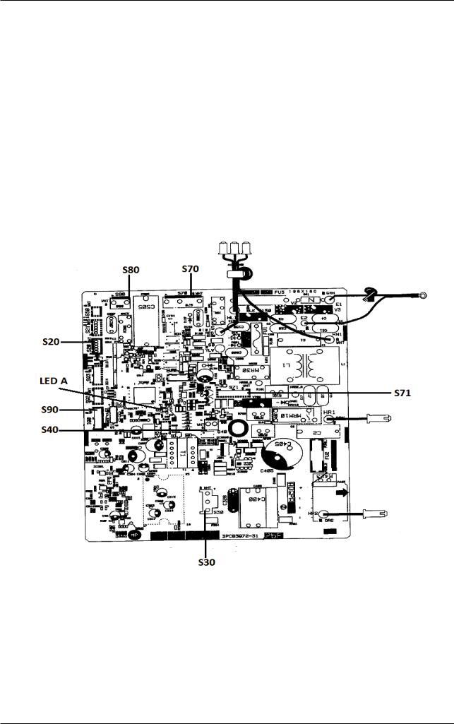
1.2.4.2 Main PCB
Item |
Indication on PCB |
Description |
|
|
|
|
|
1 |
S10 |
Connector for filter PCB |
|
|
|
|
|
2 |
S20 |
Connector for electronic expansion valve coil |
|
|
|
|
|
3 |
S40 |
Connector for overload protector |
|
|
|
|
|
4 |
S70 |
Connector for fan motor |
|
|
|
|
|
5 |
S80 |
Connector for four way valve coil |
|
|
|
|
|
6 |
S90 |
Connector for thermistors (outdoor temperature, |
|
outdoor heat exchanger, discharge pipe) |
|||
|
|
||
7 |
HL3, HN3 |
Connector for filter PCB |
|
|
|
|
|
8 |
FU1, FU2 |
Fuse (3.15A) |
|
|
|
|
|
9 |
LED A |
Service monitor LED (green) |
|
|
|
|
|
10 |
V1 |
Varistor |
|
|
|
|
9
Inverter Single Split
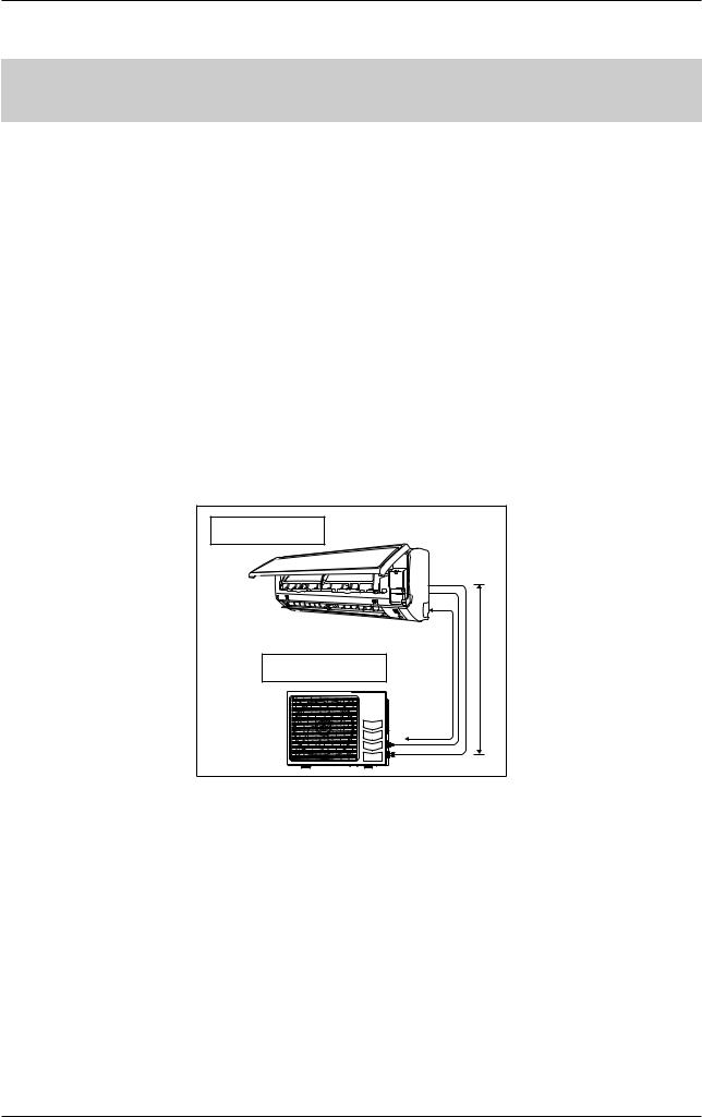
1.3 Piping Length & Elevation
|
Max. total piping |
Max. height |
Pre-charge for o |
Additional charge |
|
Model |
length, L |
difference, E |
to piping length |
||
[oz/ft (g/m)] |
|||||
|
[ft,(m)] |
[ft,(m)] |
[ft,(m)] |
||
|
|
||||
|
|
|
|
|
|
RK(X)B09AX |
65.6 (20) |
32.8 (10) |
25 (7.6) |
0.21 (20) |
|
RK(X)N09AX |
|||||
|
|
|
|
||
|
|
|
|
|
|
RK(X)B12AX |
65.6 (20) |
32.8 (10) |
25 (7.6) |
0.21 (20) |
|
RK(X)N12AX |
|||||
|
|
|
|
||
|
|
|
|
|
|
RK(X)B18AX |
98.4 (30) |
32.8 (10) |
25 (7.6) |
0.21 (20) |
|
RK(X)N18AX |
|||||
|
|
|
|
||
|
|
|
|
|
|
RK(X)B24AX |
98.4 (30) |
32.8 (10) |
25 (7.6) |
0.21 (20) |
|
RK(X)N24AX |
|||||
|
|
|
|
||
|
|
|
|
|
Remark : The refrigerant pre-charged in the outdoor unit is for piping length up to 25ft (7.6m).
Indoor unit |
|
|
Outdoor Unit |
L |
E |
10
Inverter Single Split
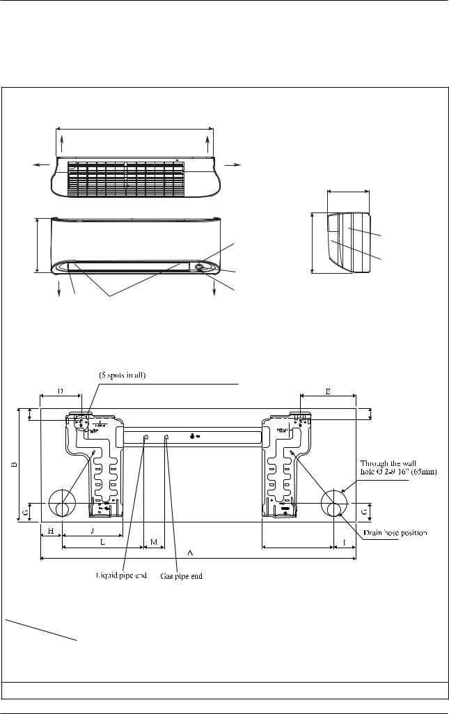
1.4 Outline & Dimension
1.4.1 Indoor Unit
Model: FTK(X)B09/12AX, FTK(X)N09/12AX
THE MARK

 SHOWS PIPING DIRECTION
|
A |
REAR |
REAR |
LEFT |
|
|
TOP VIEW |
B |
|
BOTTOM |
BOTTOM |
LOUVER |
FRONT GRILLE FIXED SCREWS |
|
(INSIDE) |
|
FRONT VIEW |
FOR ILLUSTRATIVE PURPOSES ONLY
RIGHT
C
SIGNAL RECEIVER |
B |
NAME PLATE |
|
||
|
|
TERMINAL |
|
|
BLOCK |
INDOOR UNIT |
|
WITH EARTH |
ON/OFF SWITCH |
SIDE VIEW |
TERMINAL |
ROOM TEMPERATURE THERMISTOR (INSIDE)

F |
F |
K
 09/12
09/12
Model |
Dimension |
A |
B |
C |
D |
E |
F |
G |
H |
I |
J |
K |
L |
M |
|
||||||||||||||
|
|
|
|
|
|
|
|
|
|
|
|
|
|
|
|
09/12 |
35-1/16 |
11-11/16 |
8-1/4 |
4-1/16 |
5-9/16 |
1-3/16 |
1-13/16 |
2-3/16 |
2-3/16 |
6 |
7-1/8 |
8-1/8 |
2-1/16 |
|
(890) |
(297) |
(210) |
(104) |
(141) |
(30) |
(46) |
(55) |
(56) |
(153) |
(181) |
(207) |
(52) |
|
|
|
|||||||||||||
|
|
|
|
|
|
|
|
|
|
|
|
|
|
|
Note: Dimension in inch (mm)
11
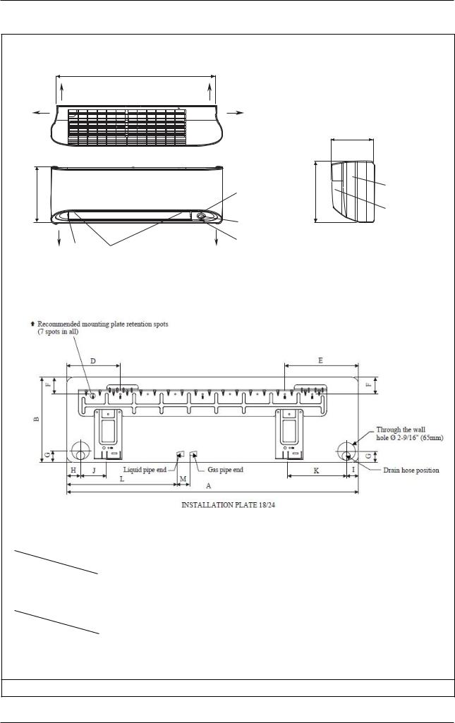
Inverter Single Split
Model: FTK(X)B18/24AX, FTK(X)N18/24AX
THE MARK

 SHOWS PIPING DIRECTION
|
A |
REAR |
REAR |
LEFT |
|
|
TOP VIEW |
B |
|
BOTTOM |
BOTTOM |
LOUVER |
FRONT GRILLE FIXED SCREWS |
|
(INSIDE) |
|
FRONT VIEW |
FOR ILLUSTRATIVE PURPOSES ONLY
RIGHT
C
SIGNAL RECEIVER |
B |
NAME PLATE |
|
||
|
|
TERMINAL |
|
|
BLOCK |
INDOOR UNIT |
|
WITH EARTH |
ON/OFF SWITCH |
SIDE VIEW |
TERMINAL |
ROOM TEMPERATURE THERMISTOR (INSIDE)
Model |
Dimension |
A |
B |
C |
D |
E |
F |
G |
|
||||||||
|
|
|
|
|
|
|
|
|
|
|
|
|
|
|
|
|
|
|
18/24 |
46-1/8 |
12-5/8 |
9-1/2 |
7-1/2 |
6-13/16 |
2-3/8 |
1-9/16 |
|
(1172) |
(320) |
(242) |
(190) |
(173) |
(61) |
(40) |
|
|
|
|||||||
|
|
|
|
|
|
|
|
|
Model |
Dimension |
H |
I |
J |
K |
L |
M |
|
|
|
|||||||
|
|
|
|
|
|
|
|
|
|
|
|
|
|
|
|
|
|
|
18/24 |
1-3/4 |
1-7/8 |
3-9/16 |
8-5/8 |
22-13/16 |
1-3/4 |
|
|
(45) |
(48) |
(91) |
(219) |
(580) |
(45) |
|
|
|
|
|
Note: Dimension in inch (mm)
12
Inverter Single Split
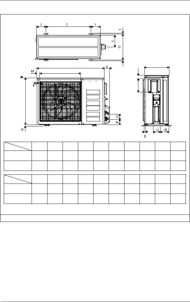
1.4.2 Outdoor Unit
Model: RK(X)B09/12AX, RK(X)N09/12AX
J
G
E |
F |
2.0 |
D |
|
|
||
|
|
|
|
|
|
|
A |
FOR ILLUSTRATIVE PURPOSES ONLY
H I
 O
O
N
|
Q |
|
P |
B |
C |
L
 MK
MK
Model |
Dimension |
A |
|
B |
C |
D |
E |
F |
G |
H |
I |
|
|
||||||||||
|
|
|
|
|
|
|
|
|
|
|
|
|
09/12 |
21-5/8 |
22-15/16 |
2 |
7/16 |
10-3/4 |
5/8 |
9/16 |
18-1/2 |
3-3/4 |
|
|
(550) |
(658) |
(51) |
(11) |
(273) |
(16) |
(14) |
(470) |
(96) |
||
|
|
||||||||||
|
|
|
|
|
|
|
|
|
|
|
|
Model |
Dimension |
J |
|
K |
L |
M |
N |
O |
P |
Q |
|
|
|
|
|||||||||
|
|
|
|
|
|
|
|
|
|
|
|
|
09/12 |
3-11/16 |
3-11/16 |
2-3/8 |
9/16 |
5-1/4 |
5/16 |
3/8 |
11-3/4 |
|
|
|
(93) |
|
(94) |
(60) |
(14) |
(133) |
(8) |
(10) |
(299) |
|
|
|
|
|
|
||||||||
Note: Dimension in inch (mm)
13
Inverter Single Split
Model: RK(X)B18/24AX, RK(X)N18/24AX
FOR ILLUSTRATIVE PURPOSES ONLY
|
|
A |
N |
C |
|
D |
|
|
|
3.0 |
|
|
F |
|
|
|
|
|
|
|
|
|
|
E |
B |
|
|
|
|
Dimension |
A |
B |
C |
D |
E |
F |
G |
H |
I |
J |
|
Model |
|||||||||||
|
|
|
|
|
|
|
|
|
|
||
18 |
33-11/16 |
24-3/4 |
12-15/16 |
20-1/2 |
7-1/16 |
1-13/16 |
4 |
4-7/16 |
23-3/4 |
4-15/16 |
|
(855) |
(628) |
(328) |
(520) |
(179) |
(46) |
(101) |
(113) |
(603) |
(126) |
||
|
|||||||||||
24 |
33-11/16 |
28-3/4 |
12-15/16 |
20-1/2 |
7-1/16 |
1-13/16 |
4 |
4-7/16 |
23-3/4 |
4-15/16 |
|
(855) |
(730) |
(328) |
(520) |
(179) |
(46) |
(101) |
(113) |
(603) |
(126) |
||
|
Dimension |
K |
L |
M |
N |
O |
P |
Q |
R |
S |
T |
|
Model |
|||||||||||
|
|
|
|
|
|
|
|
|
|
||
18 |
6-7/16 |
9/16 |
1-5/16 |
15/16 |
14-1/4 |
2-7/8 |
2-15/16 |
5/16 (8) |
2-5/8 |
1/4 |
|
|
(164) |
(15) |
(34) |
(23) |
(362) |
(73) |
(75) |
|
(67) |
(7) |
|
24 |
6-7/16 |
9/16 |
1-5/16 |
15/16 |
14-1/4 |
2-7/8 |
2-15/16 |
5/16 (8) |
2-5/8 |
1/4 |
|
|
(164) |
(15) |
(34) |
(23) |
(362) |
(73) |
(75) |
|
(67) |
(7) |
Note: Dimension in inch (mm)
14

Inverter Single Split
1.5 Engineering Data
1.5.1 Cooling Only
Model |
Indoor unit |
|
FTKB09AXVJU |
FTKB12AXVJU |
FTKB18AXVJU |
FTKB24AXVJU |
|||
Outdoor unit |
|
RKB09AXVJU |
RKB12AXVJU |
RKB18AXVJU |
RKB24AXVJU |
||||
|
|
|
|||||||
Nominal Cooling Capacity (Min. ~ Max.) |
Btu/h |
8800 (4400 - 10200) |
11000 (4400 - 13000) |
18000 (4300 - 21200) |
21200 (6000 - 22200) |
||||
W |
2570 (1300 - 3000) |
3220 (1300 - 3800) |
5270 (1260 - 6200) |
6210 (1750 - 6500) |
|||||
|
|
|
|
||||||
|
|
|
|
|
|
|
|
||
Nominal Total Input Power |
W |
800 |
1294 |
1710 |
1927 |
||||
|
|
|
|
|
|
|
|
||
Nominal Running Current |
A |
3.60 |
5.79 |
7.48 |
8.47 |
||||
|
|
|
|
|
|
|
|
||
SEER |
|
17 |
17 |
17 |
17 |
||||
|
|
|
|
|
|
|
|
|
|
EER |
|
|
|
(Btu/h)/W |
11.00 |
8.50 |
10.50 |
11.00 |
|
Power Supply |
V/Ph/Hz |
208/230/1/60 |
208/230/1/60 |
208/230/1/60 |
208/230/1/60 |
||||
|
Airflow (H/M/L/T/Q) |
cfm |
330/272/215/378/165 |
360/282/232/392/165 |
430/374/318/486/274 |
555/486/405/605/336 |
|||
UNIT |
Sound Pressure Level (H/M/L/T/Q) |
dB(A) |
42/35/30/43/23 |
42/35/32/43/22 |
40/37/35/43/32 |
47/44/41/49/37 |
|||
Height |
in. (mm) |
11-11/16 (297) |
11-11/16 (297) |
12-5/8 (320) |
12-5/8 (320) |
||||
INDOOR |
|||||||||
Depth |
in. (mm) |
8-1/4 (210) |
8-1/4 (210) |
9-1/2 (242) |
9-1/2 (242) |
||||
|
Width |
in. (mm) |
35-1/16 (890) |
35-1/16 (890) |
46-1/8 (1172) |
46-1/8 (1172) |
|||
|
|
|
|
|
|
|
|
||
|
Machine Weight |
lbs (kg) |
20 (9) |
20 (9) |
31 (14) |
31 (14) |
|||
|
|
|
|
|
|
|
|
||
UNIT |
Sound Pressure Level |
dB(A) |
46 |
48 |
53 |
52 |
|||
Height |
in. (mm) |
21-5/8 (550) |
21-5/8 (550) |
25-11/16 (651) |
29-11/16 (753) |
||||
OUTDOOR |
|
|
|
|
|
|
|
|
|
Width |
in. (mm) |
25-15/16 (658) |
25-15/16 (658) |
33-11/16 (855) |
33-11/16 (855) |
||||
|
|||||||||
|
Depth |
in. (mm) |
10-3/4 (273) |
10-3/4 (273) |
12-15/16 (328) |
12-15/16 (328) |
|||
|
Machine Weight |
lbs (kg) |
53 (24) |
57 (26) |
82 (37) |
97 (44) |
|||
Piping Connections |
Liquid |
in. (mm) |
1/4 (6.35) |
1/4 (6.35) |
1/4 (6.35) |
1/4 (6.35) |
|||
|
|
|
|
|
|
||||
Gas |
in. (mm) |
3/8 (9.52) |
3/8 (9.52) |
1/2 (12.70) |
5/8 (15.88) |
||||
|
|
|
|||||||
|
|
|
|
|
|
|
|||
Operation Range |
°F |
50 ~115 |
50 ~115 |
14 ~115 |
14 ~115 |
||||
|
|
|
|
|
|
|
|
||
Model |
Indoor unit |
|
FTKN09AXVJU |
FTKN12AXVJU |
FTKN18AXVJU |
FTKN24AXVJU |
|||
|
|
|
|
|
|
||||
Outdoor unit |
|
RKN09AXVJU |
RKN12AXVJU |
RKN18AXVJU |
RKN24AXVJU |
||||
|
|
|
|||||||
Nominal Cooling Capacity (Min. ~ Max.) |
Btu/h |
8800 (4400 - 10200) |
11000 (4400 - 13000) |
18000 (4300 - 21200) |
21200 (6000 - 22200) |
||||
|
|
|
|
|
|||||
W |
2570 (1300 - 3000) |
3220 (1300 - 3800) |
5270 (1260 - 6200) |
6210 (1750 - 6500) |
|||||
|
|
|
|
||||||
Nominal Total Input Power |
W |
800 |
1294 |
1710 |
1927 |
||||
Nominal Running Current |
A |
3.60 |
5.79 |
7.48 |
8.47 |
||||
SEER |
|
17 |
17 |
17 |
17 |
||||
EER |
|
|
|
(Btu/h)/W |
11.00 |
8.50 |
10.50 |
11.00 |
|
Power Supply |
V/Ph/Hz |
208/230/1/60 |
208/230/1/60 |
208/230/1/60 |
208/230/1/60 |
||||
|
Airflow (H/M/L/T/Q) |
cfm |
330/272/215/378/165 |
360/282/232/392/165 |
430/374/318/486/274 |
555/486/405/605/336 |
|||
UNIT |
|
|
|
|
|
|
|||
Sound Pressure Level (H/M/L/T/Q) |
dB(A) |
42/35/30/43/23 |
42/35/32/43/22 |
40/37/35/43/32 |
47/44/41/49/37 |
||||
|
|
|
|
|
|
|
|
||
Height |
in. (mm) |
11-5/16 (288) |
11-5/16 (288) |
12-3/16 (310) |
12-3/16 (310) |
||||
INDOOR |
|||||||||
|
|
|
|
|
|
||||
Depth |
in. (mm) |
8-1/4 (209) |
8-1/4 (209) |
9-5/16 (237) |
9-5/16 (237) |
||||
|
Width |
in. (mm) |
33-13/16 (859) |
33-13/16 (859) |
44-1/4 (1124) |
44-1/4 (1124) |
|||
|
|
|
|
|
|
|
|||
|
Machine Weight |
lbs (kg) |
20 (9) |
20 (9) |
31 (14) |
31 (14) |
|||
UNIT |
Sound Pressure Level |
dB(A) |
46 |
48 |
53 |
52 |
|||
Height |
in. (mm) |
21-5/8 (550) |
21-5/8 (550) |
25-11/16 (651) |
29-11/16 (753) |
||||
OUTDOOR |
|
|
|
|
|
|
|
|
|
Width |
in. (mm) |
25-15/16 (658) |
25-15/16 (658) |
33-11/16 (855) |
33-11/16 (855) |
||||
|
|||||||||
|
|
|
|
|
|
|
|||
|
Depth |
in. (mm) |
10-3/4 (273) |
10-3/4 (273) |
12-15/16 (328) |
12-15/16 (328) |
|||
|
|
|
|
|
|
|
|||
|
Machine Weight |
lbs (kg) |
53 (24) |
57 (26) |
82 (37) |
97 (44) |
|||
|
|
|
|
|
|
|
|
|
|
Piping Connections |
Liquid |
in. (mm) |
1/4 (6.35) |
1/4 (6.35) |
1/4 (6.35) |
1/4 (6.35) |
|||
Gas |
in. (mm) |
3/8 (9.52) |
3/8 (9.52) |
1/2 (12.70) |
5/8 (15.88) |
||||
|
|
|
|||||||
Operation Range |
°F |
50 ~115 |
50 ~115 |
14 ~115 |
14 ~115 |
||||
15
|
|
|
|
|
|
|
|
|
Inverter Single Split |
|
1.5.2 Heatpump |
|
|
|
|
|
|||||
|
|
|
|
|
|
|
|
|
|
|
Model |
Indoor unit |
|
FTXB09AXVJU |
FTXB12AXVJU |
FTXB18AXVJU |
FTXB24AXVJU |
||||
|
|
|
|
|
|
|
||||
Outdoor unit |
|
RXB09AXVJU |
RXB12AXVJU |
RXB18AXVJU |
RXB24AXVJU |
|||||
|
|
|
|
|||||||
Nominal Cooling Capacity (Min. ~ Max.) |
Btu/h |
8800 (4400 - 10200) |
11000 (4400 - 13000) |
18000 (4300 - 21200) |
21200 (6000 - 22200) |
|||||
|
|
|
|
|
||||||
W |
2570 (1300 - 3000) |
3220 (1300 - 3800) |
5270 (1260 - 6200) |
6210 (1750 - 6500) |
||||||
|
|
|
|
|
||||||
|
|
|
|
|
|
|
|
|
|
|
Nominal Heating Capacity (Min. ~ Max.) |
Btu/h |
9400 (4400 - 13600) |
11300 (4400 - 16200) |
17900 (4000 - 22500) |
21200 (4100 - 27300) |
|||||
W |
2750 (1300 - 4000) |
3310 (1300 - 4750) |
5240 (1170 - 6600) |
6210 (1200 - 8000) |
||||||
|
|
|
|
|
||||||
Nominal Total Input Power (Cooling) |
W |
800 |
1294 |
1710 |
1927 |
|||||
Nominal Total Input Power (Heating) |
W |
774 |
1004 |
1590 |
1688 |
|||||
Nominal Running Current (Cooling) |
A |
3.60 |
5.79 |
7.48 |
8.47 |
|||||
Nominal Running Current (Heating) |
A |
3.51 |
4.60 |
7.03 |
7.56 |
|||||
|
|
|
|
|
|
|
|
|||
SEER |
|
17 |
17 |
17 |
17 |
|||||
|
|
|
|
|
|
|
|
|
|
|
EER |
|
|
|
(Btu/h)/W |
11.00 |
8.50 |
10.50 |
11.00 |
||
|
|
|
|
|
|
|
|
|||
COP |
(Btu/h)/W |
12.15 |
11.26 |
11.26 |
12.56 |
|||||
HSPF |
|
9 |
9 |
9 |
9 |
|||||
Power Supply |
V/Ph/Hz |
208/230/1/60 |
208/230/1/60 |
208/230/1/60 |
208/230/1/60 |
|||||
|
|
Airflow (H/M/L/T/Q) (Cooling) |
cfm |
330/272/215/378/165 |
360/282/232/392/165 |
430/374/318/486/274 |
555/486/405/605/336 |
|||
UNIT |
|
Airflow (H/M/L/T/Q) (Heating) |
cfm |
330/272/215/378/165 |
360/282/232/392/165 |
435/374/318/486/274 |
580/486/405/605/336 |
|||
|
Sound Pressure Level (H/M/L/T/Q) |
dB(A) |
42/35/30/43/23 |
42/35/32/43/22 |
40/37/35/43/32 |
47/44/41/49/37 |
||||
|
|
|||||||||
INDOOR |
|
|
|
|
|
|
|
|
|
|
|
Height |
in. (mm) |
11-11/16 (297) |
11-11/16 (297) |
12-5/8 (320) |
12-5/8 (320) |
||||
|
|
|||||||||
|
|
|
|
|
|
|
|
|
||
|
|
Width |
in. (mm) |
35-1/16 (890) |
35-1/16 (890) |
46-1/8 (1172) |
46-1/8 (1172) |
|||
|
|
|
|
|
|
|
|
|
||
|
|
Depth |
in. (mm) |
8-1/4 (210) |
8-1/4 (210) |
9-1/2 (242) |
9-1/2 (242) |
|||
|
|
|
|
|
|
|
|
|
||
|
|
Machine Weight |
lbs (kg) |
20 (9) |
20 (9) |
31 (14) |
31 (14) |
|||
UNIT |
|
Sound Pressure Level |
dB(A) |
46 |
48 |
53 |
52 |
|||
|
Height |
in. (mm) |
21-5/8 (550) |
21-5/8 (550) |
25-11/16 (651) |
29-11/16 (753) |
||||
OUTDOOR |
|
|
|
|
|
|
|
|
|
|
|
Width |
in. (mm) |
25-15/16 (658) |
25-15/16 (658) |
33-11/16 (855) |
33-11/16 (855) |
||||
|
|
|||||||||
|
|
Depth |
in. (mm) |
10-3/4 (273) |
10-3/4 (273) |
12-15/16 (328) |
12-15/16 (328) |
|||
|
|
Machine Weight |
lbs (kg) |
53 (24) |
57 (26) |
82 (37) |
97 (44) |
|||
|
|
|
|
|
|
|
|
|
|
|
Piping Connections |
Liquid |
in. (mm) |
1/4 (6.35) |
1/4 (6.35) |
1/4 (6.35) |
1/4 (6.35) |
||||
|
|
|
|
|
|
|||||
Gas |
in. (mm) |
3/8 (9.52) |
3/8 (9.52) |
1/2 (12.70) |
5/8 (15.88) |
|||||
|
|
|
|
|||||||
|
|
|
|
|
|
|
|
|
|
|
Operation Range |
Cooling |
°F |
50 ~115 |
50 ~115 |
14 ~115 |
14 ~115 |
||||
Heating |
°F |
5 ~ 64.4 |
5 ~ 64.4 |
5 ~ 64.4 |
5 ~ 64.4 |
|||||
|
|
|
|
|||||||
|
|
|
|
|
|
|
|
|
||
Model |
Indoor unit |
|
FTXN09AXVJU |
FTXN12AXVJU |
FTXN18AXVJU |
FTXN24AXVJU |
||||
|
|
|
|
|
|
|||||
Outdoor unit |
|
RXN09AXVJU |
RXN12AXVJU |
RXN18AXVJU |
RXN24AXVJU |
|||||
|
|
|
|
|||||||
Nominal Cooling Capacity (Min. ~ Max.) |
Btu/h |
8800 (4400 - 10200) |
11000 (4400 - 13000) |
18000 (4300 - 21200) |
21200 (6000 - 22200) |
|||||
W |
2570 (1300 - 3000) |
3220 (1300 - 3800) |
5270 (1260 - 6200) |
6210 (1750 - 6500) |
||||||
|
|
|
|
|
||||||
Nominal Heating Capacity (Min. ~ Max.) |
Btu/h |
9400 (4400 - 13600) |
11300 (4400 - 16200) |
17900 (4000 - 22500) |
21200 (4100 - 27300) |
|||||
W |
2750 (1300 - 4000) |
3310 (1300 - 4750) |
5240 (1170 - 6600) |
6210 (1200 - 8000) |
||||||
|
|
|
|
|
||||||
Nominal Total Input Power (Cooling) |
W |
800 |
1294 |
1710 |
1927 |
|||||
|
|
|
|
|
|
|||||
Nominal Total Input Power (Heating) |
W |
774 |
1004 |
1590 |
1688 |
|||||
|
|
|
|
|
|
|||||
Nominal Running Current (Cooling) |
WWA |
3.60 |
5.79 |
7.48 |
8.47 |
|||||
|
|
|
|
|
|
|||||
Nominal Running Current (Heating) |
A |
3.51 |
4.60 |
7.03 |
7.56 |
|||||
SEER |
|
17 |
17 |
17 |
17 |
|||||
EER |
|
|
|
(Btu/h)/W |
11.00 |
8.50 |
10.50 |
11.00 |
||
COP |
(Btu/h)/W |
12.15 |
11.26 |
11.26 |
12.56 |
|||||
HSPF |
|
9 |
9 |
9 |
9 |
|||||
Power Supply |
V/Ph/Hz |
208/230/1/60 |
208/230/1/60 |
208/230/1/60 |
208/230/1/60 |
|||||
|
|
Airflow (H/M/L/T/Q) (Cooling) |
cfm |
330/272/215/378/165 |
360/282/232/392/165 |
430/374/318/486/274 |
555/486/405/605/336 |
|||
|
|
|
|
|
|
|
|
|||
UNIT |
|
Airflow (H/M/L/T/Q) (Heating) |
cfm |
330/272/215/378/165 |
360/282/232/392/165 |
435/374/318/486/274 |
580/486/405/605/336 |
|||
|
|
|
|
|
|
|
|
|
||
|
Sound Pressure Level (H/M/L/T/Q) |
dB(A) |
42/35/30/43/23 |
42/35/32/43/22 |
40/37/35/43/32 |
47/44/41/49/37 |
||||
|
|
|||||||||
INDOOR |
|
|
|
|
|
|
|
|
|
|
|
Height |
in. (mm) |
11-5/16 (288) |
11-5/16 (288) |
12-3/16 (310) |
12-3/16 (310) |
||||
|
|
|||||||||
|
|
Width |
in. (mm) |
33-13/16 (859) |
33-13/16 (859) |
44-1/4 (1124) |
44-1/4 (1124) |
|||
|
|
Depth |
in. (mm) |
8-1/4 (209) |
8-1/4 (209) |
9-5/16 (237) |
9-5/16 (237) |
|||
|
|
Machine Weight |
lbs (kg) |
20 (9) |
20 (9) |
31 (14) |
31 (14) |
|||
UNIT |
|
Sound Pressure Level |
dB(A) |
46 |
48 |
53 |
52 |
|||
|
Height |
in. (mm) |
21-5/8 (550) |
21-5/8 (550) |
25-11/16 (651) |
29-11/16 (753) |
||||
OUTDOOR |
|
|
|
|
|
|
|
|
|
|
|
Width |
in. (mm) |
25-15/16 (658) |
25-15/16 (658) |
33-11/16 (855) |
33-11/16 (855) |
||||
|
|
|||||||||
|
|
|
|
|
|
|
|
|||
|
|
Depth |
in. (mm) |
10-3/4 (273) |
10-3/4 (273) |
12-15/16 (328) |
12-15/16 (328) |
|||
|
|
|
|
|
|
|
|
|||
|
|
Machine Weight |
lbs (kg) |
53 (24) |
57 (26) |
82 (37) |
97 (44) |
|||
Piping Connections |
Liquid |
in. (mm) |
1/4 (6.35) |
1/4 (6.35) |
1/4 (6.35) |
1/4 (6.35) |
||||
Gas |
in. (mm) |
3/8 (9.52) |
3/8 (9.52) |
1/2 (12.70) |
5/8 (15.88) |
|||||
|
|
|
|
|||||||
Operation Range |
Cooling |
°F |
50 ~115 |
50 ~115 |
14 ~115 |
14 ~115 |
||||
Heating |
°F |
5 ~ 64.4 |
5 ~ 64.4 |
5 ~ 64.4 |
5 ~ 64.4 |
|||||
|
|
|
|
|||||||
|
|
|
|
|
|
|
|
|
|
|
16
Algorithm & Control
2.0Function & Control
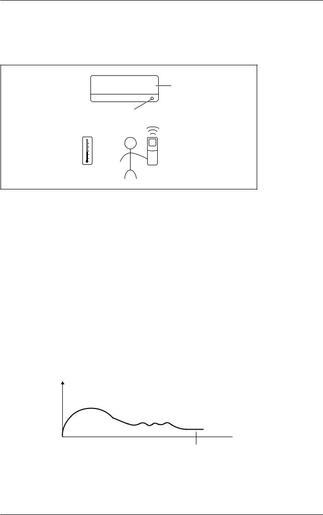
2.1Temperature Control
The temperature is detected by the room temperature thermistor (either on the unit or on the wired panel). The set temperature can be selected either through remote controller or wired controller by user.
Target temperature
Room thermistor temperature
Set temperature
Room temperature
2.2 Cooling and Heating Mode Operation
The system has 5 operating modes. The mode selection is done through the indoor by using the remote controller.
The operating modes are:
•Cool
•Heat
•Fan
•Auto
•Dry
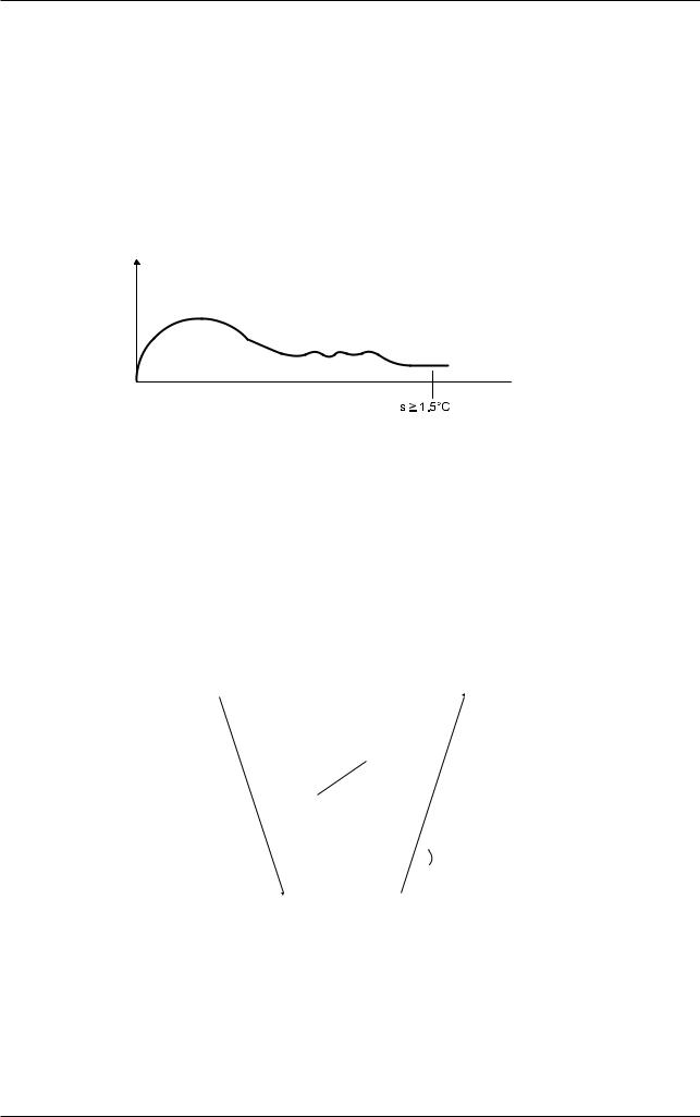
2.2.1 Cooling Mode
When Tr ≥ Ts + 1.5°C (2.7°F)
• Compressor, Indoor Fan and Outdoor Fan ON.
When Tr ≤ Ts - 2°C (3.6°F)
• Compressor and Outdoor Fan OFF. Indoor Fan remained ON.
Tr = Room Temperature
Ts = Set Temperature
When cooling load is too small and the room temperature still drops below compressor cut off point, compressor will stop.
Compressor Capacity
Lowest Frequency
 Time
Time
T Ts - 2°C (3.6°F)
Compressor will stop
17
Algorithm & Control
2.2.2 Heating Mode:
When Ts > Tr - 1.0°C (1.8°F)
• Compressor, Indoor Fan and Outdoor Fan ON.
When Ts ≤ Tr - 1.5°C (2.7°F)
• Compressor and Outdoor Fan OFF. Indoor Fan speed will change to Super Low.
Tr = Room Temperature
Ts = Set Temperature
When heating load is too small, and the room temperature is still rising above compressor cut off point, compressor will stop.
Compressor Capacity
Lowest Frequency 

 Time
Time
Tr - T (2.7°F)
Compressor will stop
2.3 Dry Mode
Program dry operation removes humidity while preventing the room temperature from lowering. Since the microcomputer controls both the temperature and airflow rate, the temperature adjustment and FAN setting buttons are inoperable.
The microcomputer automatically sets the temperature and airflow rate. The difference between the room thermistor temperature at start-up and the target temperature is divided into two zones. Then, the unit operates in an appropriate capacity for each zone to maintain the temperature and humidity at a comfortable level.
|
|
|
|
|
|
|
X |
|
|
|
Zone C = Thermostat ON |
|
|||
|
|
|
|
|
|||
|
|
|
|
|
|
|
Z |
|
|
|
|
|
|
|
|
|
|
|
|
|
|
|
|
|
Zone B |
Zone B |
|||||
|
|
Y |
|
|
|
|
|
|
|
|
|
|
+0.5°C (0.9°F) |
||
|
|
|
|
|
|
||
|
|
|
Zone A= Thermostat OFF |
|
|
||
|
|
|
|
||||
Target temperature X |
Thermostat OFF point Y |
|
Thermostat ON point Z* |
||||
Setting temperature |
Room thermistor temperature – X = |
Room thermistor temperature – X = |
|||||
-2°C (3.6°F) |
|
-0.5°C (0.9°F) |
|||||
|
|
||||||
*Thermostat turns on also when the room temperature is in the zone B for 2 minutes.
18
 Loading...