


DISCRETE SEMICONDUCTORS
BF246A; BF246B; BF246C; BF247A; BF247B; BF247C
N-channel silicon junction field-effect transistors
Product specification |
1996 Jul 29 |
Supersedes data of April 1995
File under Discrete Semiconductors, SC07
Philips Semiconductors |
Product specification |
|
|
N-channel silicon junction |
BF246A; BF246B; BF246C; |
field-effect transistors |
BF247A; BF247B; BF247C |
|
|
|
|
FEATURES
·Interchangeability of drain and source connections
·High IDSS range
·Frequency up to 450 MHz.
APPLICATIONS
·VHF and UHF amplifiers
·Mixers
·General purpose switching.
DESCRIPTION
General purpose N-channel symmetrical silicon junction field-effect transistors in a plastic TO-92 variant package.
CAUTION
The device is supplied in an antistatic package. The gate-source input must be protected against static discharge during transport or handling.
PINNING
PIN |
|
|
|
|
SYMBOL |
|
|
|
|
|
DESCRIPTION |
|||||||||
|
|
|
|
|
|
|
|
|
|
|
|
|
|
|
|
|
|
|
||
BF246A; BF246B; BF246C |
||||||||||||||||||||
|
|
|
|
|
|
|
|
|
|
|
|
|
|
|
|
|
|
|
|
|
1 |
|
|
|
|
|
|
d |
drain |
||||||||||||
2 |
|
|
|
|
|
|
g |
gate |
||||||||||||
3 |
|
|
|
|
|
|
s |
source |
||||||||||||
|
|
|
|
|
|
|
|
|
|
|
|
|
|
|
|
|
|
|
||
BF247A; BF247B; BF247C |
||||||||||||||||||||
|
|
|
|
|
|
|
|
|
|
|
|
|
|
|
|
|
|
|
|
|
1 |
|
|
|
|
|
|
d |
drain |
||||||||||||
2 |
|
|
|
|
|
|
s |
source |
||||||||||||
3 |
|
|
|
|
|
|
g |
gate |
||||||||||||
|
|
|
|
|
|
|
|
|
|
|
|
|
|
|
|
|
|
|
|
|
|
|
|
|
|
|
|
|
|
|
|
|
|
|
|
|
|
||||
|
|
1 |
|
|
|
|
|
|
|
|
|
|
|
|
|
|
||||
handbook, halfpage2 |
|
|
|
|
|
|
|
|
|
|
|
|
|
|
||||||
|
|
3 |
|
|
|
|
|
|
|
|
|
g |
|
|
|
d |
||||
|
|
|
|
|
|
|
|
|
|
|
|
|
||||||||
|
|
|
|
|
|
|
|
|
|
|
|
|
|
|
|
|
|
|
s |
|
|
|
|
|
|
|
|
|
|
|
|
|
|
|
|
|
|
|
|
||
|
|
|
|
|
|
|
|
|
|
|
|
|
|
|
|
|
|
|
|
|
|
|
|
|
|
|
|
|
|
|
|
|
|
|
|
|
MAM257 |
||||
|
|
|
|
|
|
|
|
|
|
|
|
|
|
|
|
|||||
|
|
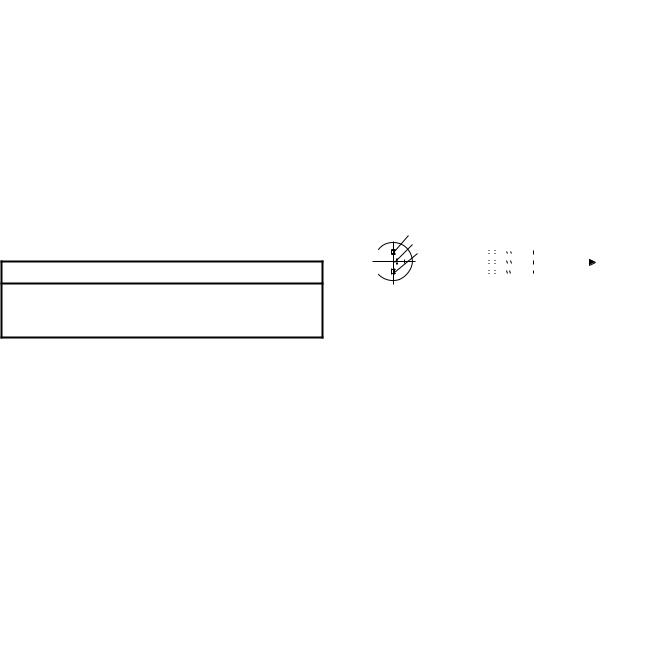
Fig.1 |
Simplified outline (TO-92 variant) |
|||||||||||||||||
|
|
|
|
|
|
|
and symbol. |
|||||||||||||
|
|
|
|
|
|
|
|
|
|
|
|
|
|
|
|
|
|
|
|
|
QUICK REFERENCE DATA
SYMBOL |
PARAMETER |
CONDITIONS |
MIN. |
TYP. |
MAX. |
UNIT |
|
|
|
|
|
|
|
VDS |
drain-source voltage |
|
- |
- |
±25 |
V |
VGSoff |
gate-source cut-off voltage |
ID = 10 nA; VDS = 15 V |
-0.6 |
- |
-14.5 |
V |
IDSS |
drain current |
VDS = 15 V; VGS = 0 |
|
|
|
|
|
BF246A; BF247A |
|
30 |
- |
80 |
mA |
|
BF246B; BF247B |
|
60 |
- |
140 |
mA |
|
BF246C; BF247C |
|
110 |
- |
250 |
mA |
|
|
|
|
|
|
|
Ptot |
total power dissipation |
up to Tamb = 50 °C |
- |
- |
400 |
mW |
ïyfsï |
forward transfer admittance |
ID = 10 mA; VDS = 15 V; |
8 |
- |
- |
mS |
|
|
f = 1 kHz |
|
|
|
|
|
|
|
|
|
|
|
Crs |
reverse transfer capacitance |
ID = 10 mA; VDS = 15 V; |
- |
3.5 |
- |
pF |
|
|
f = 1 MHz |
|
|
|
|
|
|
|
|
|
|
|
Tj |
operating junction temperature |
|
- |
- |
150 |
°C |
1996 Jul 29 |
2 |
 Loading...