


13.2. Checking and Repairing of SMPS P.C.B. & Digital Amp P.C.B.
60
manual de servicio SC-TM910DVD
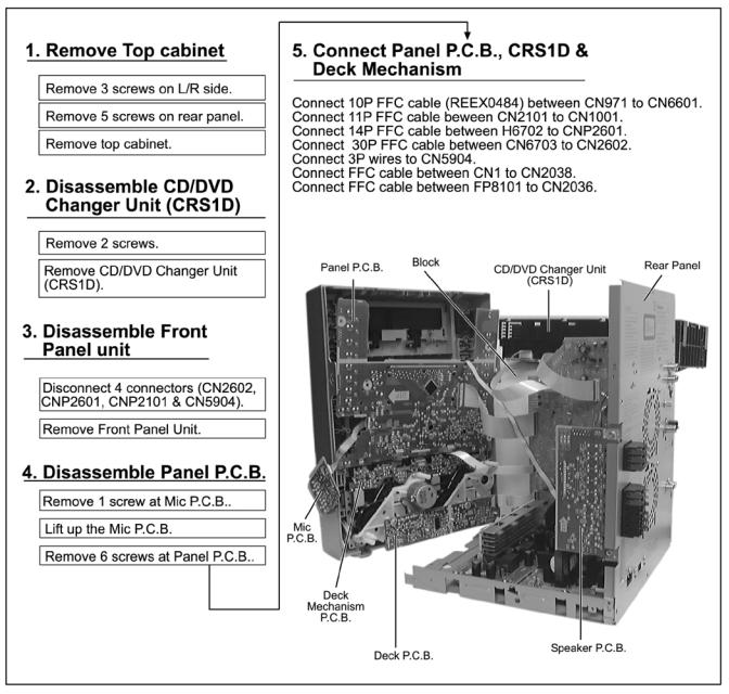
13.3. Checking and Repairing of Panel, Deck & Deck Mechanism P.C.B.
61
manual de servicio SC-TM910DVD
14 Adjustment Procedures
14.1. Cassette Deck Section
∙ Measurement Condition
− Reverse-mode selector switch:
−Tape edit: NORMAL
−Make sure head, capstan and press roller are clean.
−Judgeable room temperature 20 ± 5 °C (68 ± 9°F)
∙Measuring instrument
−EVM (DC Electronic volmeter)
−Digital frequency counter
∙Test Tape
−Tape speed gain adjustment (3 kHz, -10 dB); QZZCWAT
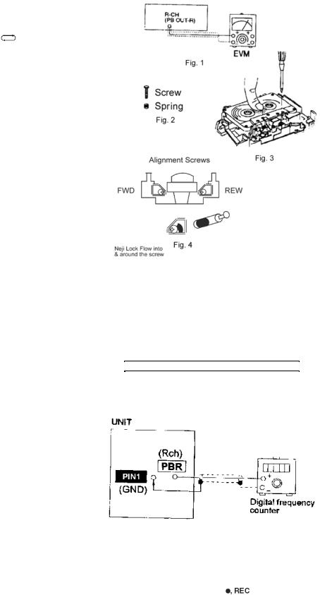
14.1.1.Head Azimuth Adjustment (Deck 1/2)
Caution:
∙Please replace both azimuth adjustment screw and springs simultaneously when readjusting the head azimuth. (shown in Fig. 2) Even if you wish to readjust the head azimuth without replacing the screws and springs, a fine adjustment to the azimuth screw and spring.
∙Please remove the screw-locking bond left on the head base when replacing the azimuth screw.
∙If you wish to readjust the head azimuth, be sure to adjust with adhering the cassette tape closely to the mechanism by pushing the center of cassette tape with your finger. (shown in Fig. 3)
1.Playback the azimuth adjustment portion (8 kHz, -20dB) of the test tape (QZZCFM) in the forward play mode. Vary the azimuth adjustment screw until the output of the R-CH (PB OUT-R) are maximized.
2.Perform the same adjustment in the reverse play mode.
3.After the adjustment, apply screwlock (NEJI-LOCK) to the azimuth adjusting screw. Screw-Lock applied on the screw must be more than 180° around screw.
14.1.2. Tape Speed Adjustment (Deck 1/2)
1.Set the tape edit button to “NORMAL” position.
2.Insert the test tape (QZZCWAT) to DECK 2 and playback (FWD side) the middle portion of it.
3.Adjust Motor VR (DECK 2) for the output value shown below.

 Adjustment target: 2910 ~ 3090 Hz (NORMAL speed)

4.After alignment, assure that the output frequency of the DECK 1 FWD are within ±90 Hz of the value of the output frequency of DECK 2 FWD.
Fig. 1
14.1.3. Bias Voltage Check
1.Set the unit “AUX” position.
2.Insert the Normal blank tape (QZZCRA) into DECK 2 and
the unit to “REC” mode (use |
key). |
3.Measure and make sure that the output is within the standard value.
62 |
Bias voltage for Deck 2 |
14±4mV (Normal) |
manual de servicio |
SC-TM910DVD |
|
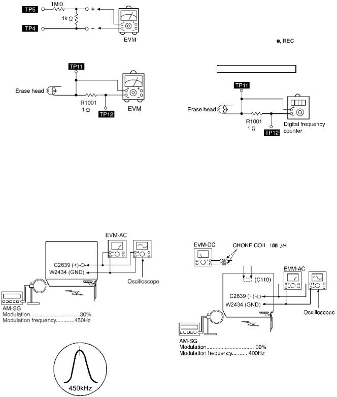
14.1.4. Bias Frequency Adjustment (Deck
1/2)
|
1. Set the unit to “AUX” position. |
|
|
2. Insert the Normal blank tape (QZZCRA) into DECK 2 and |
|
|
set the unit to “REC” mode (use |
key). |
Fig. 2 |
3. Adjust L1002 so that the output |
frequency is within the |
|
standard value. |
|

 Standard Value: 89 ~ 110 kHz
Fig. 3
|
Fig. 4 |
14.2. Tuner Section |
|
14.2.1. AM-IF Alignment |
|
1. Connect the instrument as shown in Fig. 5. |
7. Receive 600Hz in the unit. |
2. Set the unit to AM mode. |
8. Adjust L2601 (ANT) so that the EVM-SG is maximized. |
3. Apply signal as shown in Fig. 5 from AM-SG. |
9. Set AM-SG to 520kHz. |
4. Adjust Z2602 so that the output frequency is maximized in |
10. Receive 520kHz in the unit. |
Fig. 6. |
11. Adjust L2602 (OSC) so that the EVM-DC value is with |
|
|
|
1.1±0.5V. |
Fig. 5
Fig. 7
Fig. 6
14.2.2. AM RF Adjustment
1.Connect the instrument as shown in Fig. 7.
2.Set the unit to AM mode.
3.Set AM-SG to 520kHz.
4.Receive 520kHz in the unit.
5. Adjust L2601 (OSC) so that the EVM-AC is maximized. |
63 |
|
6. Set AM-SG to 600Hz. |
manual de servicio SC-TM910DVD |
|
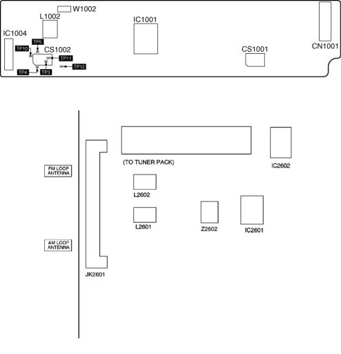
14.3. Alignment Points
14.3.1. Cassette Deck Section
14.3.2. Adjustment Point
64
manual de servicio SC-TM910DVD

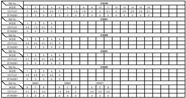
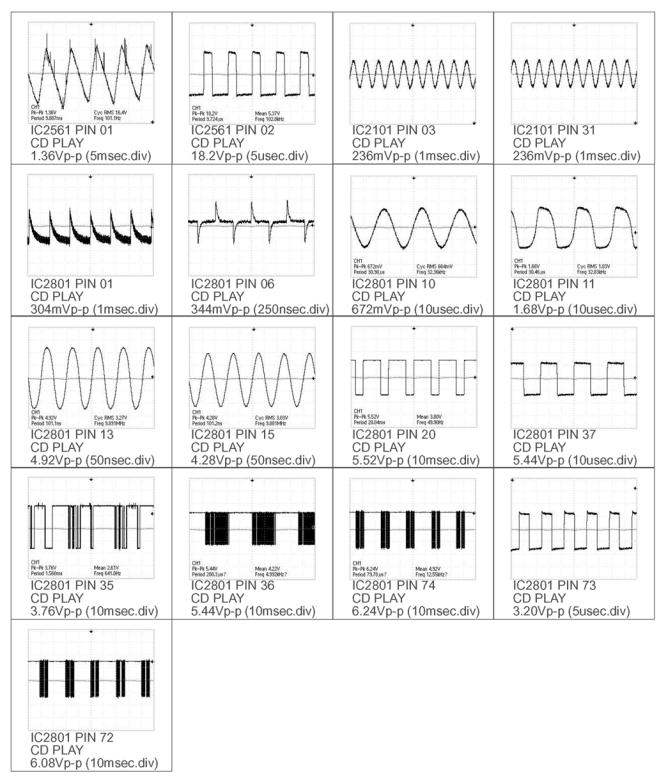
15 Voltage and Waveform Chart
Note:
Circuit voltage and waveform described herein shall be regarded as reference information when probing defect point, because it may differ from an actual measuring value due to difference of Measuring instrument and its measuring condition and product itself.
15.1. DVD Module P.C.B.
65
manual de servicio SC-TM910DVD
66
manual de servicio SC-TM910DVD
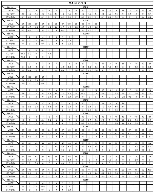
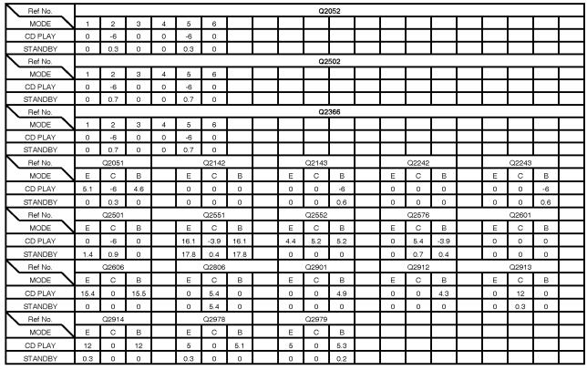
15.2. Main P.C.B.
67
manual de servicio SC-TM910DVD
68
manual de servicio SC-TM910DVD
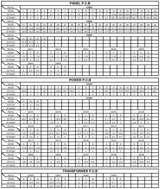
15.3. Panel P.C.B. & Power P.C.B. & Transformer P.C.B.
69
manual de servicio SC-TM910DVD
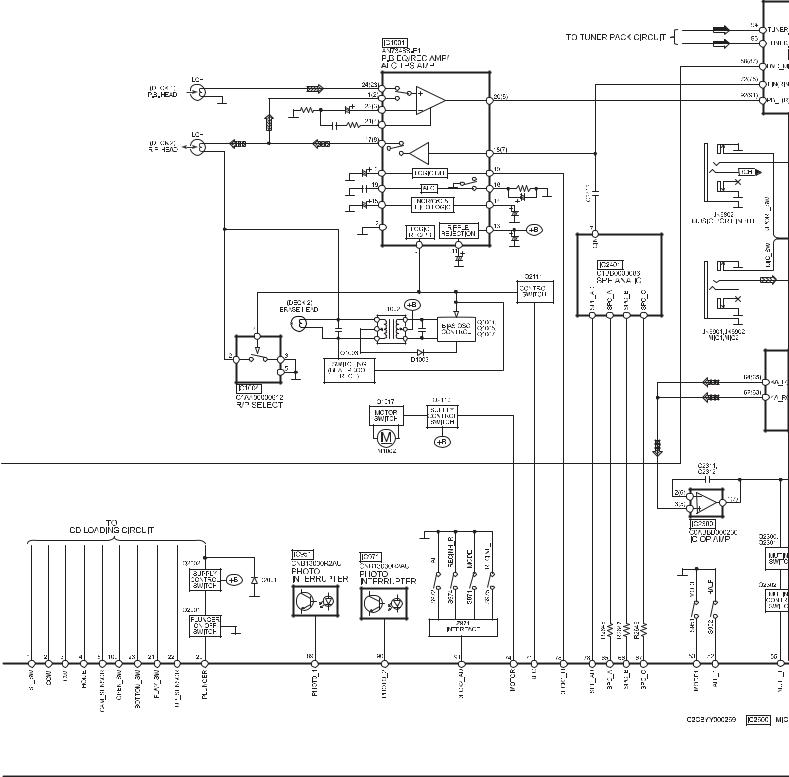
15.4. Deck P.C.B. & Deck Mechanism P.C.B. & Mic P.C.B. & Tuner P.C.B.
70
manual de servicio SC-TM910DVD
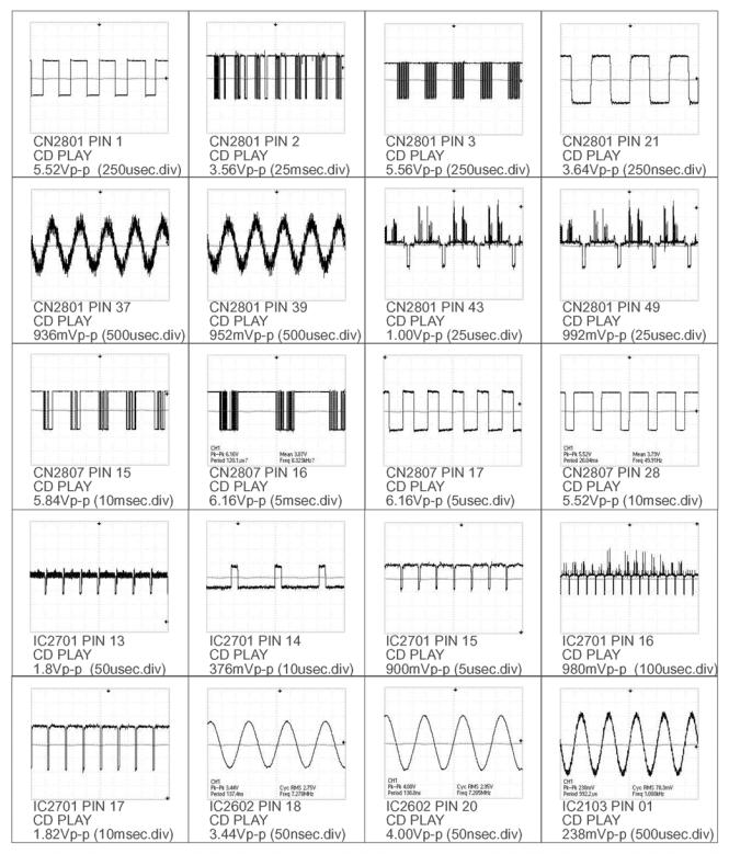
15.5. Waveform Chart
71
manual de servicio SC-TM910DVD
72
manual de servicio SC-TM910DVD
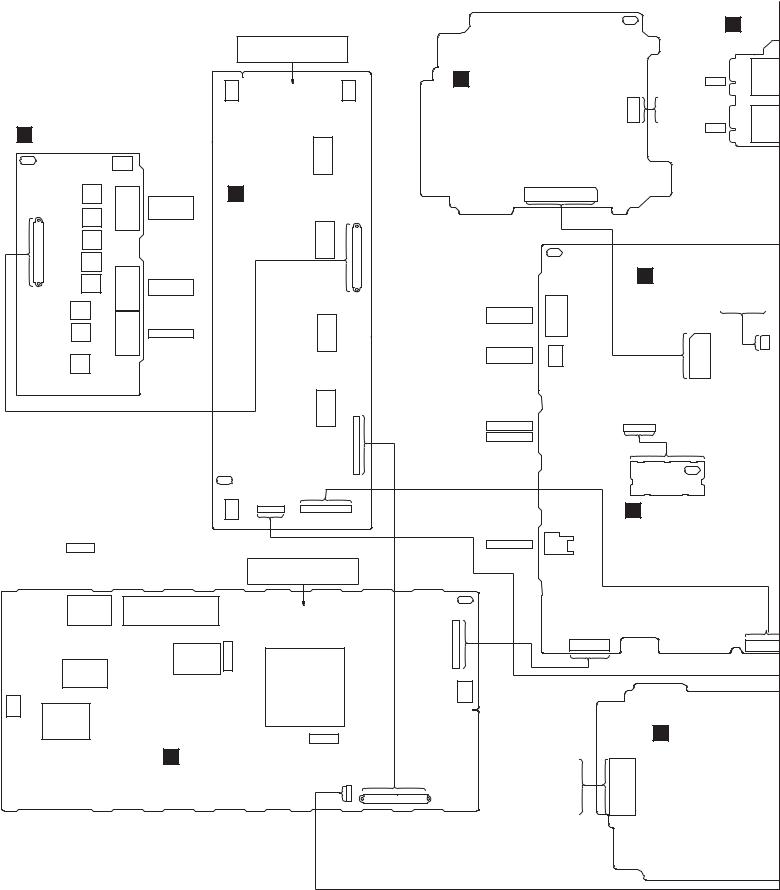
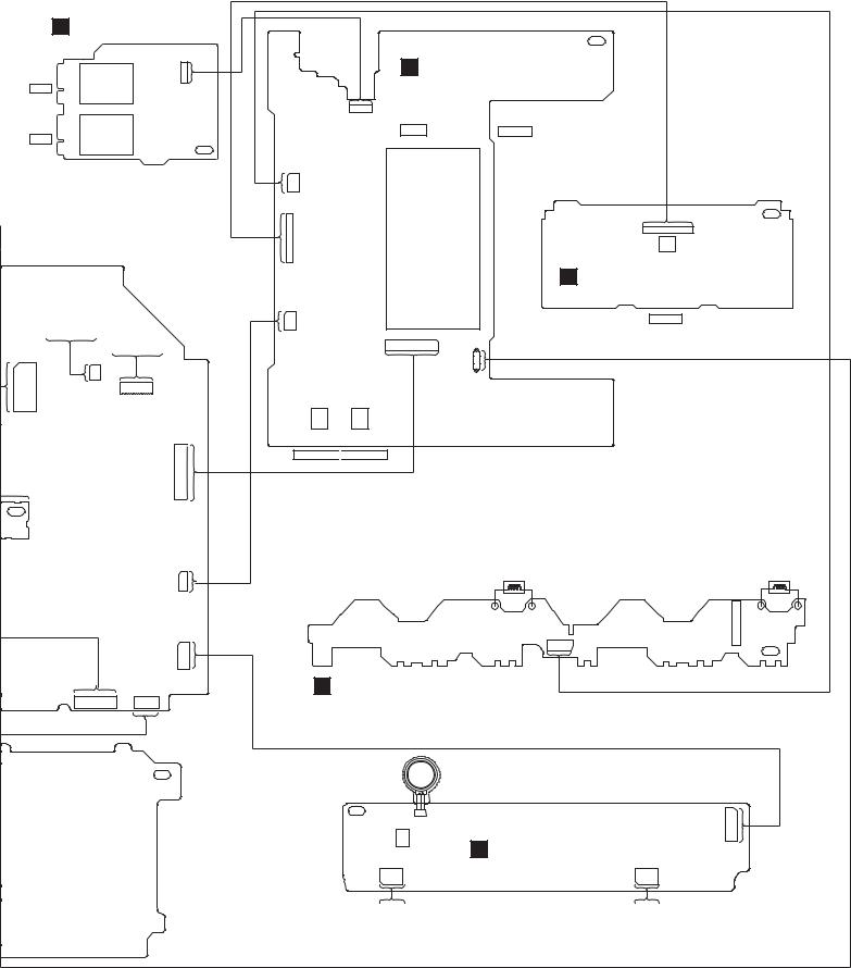
16 Wiring Connection Diagram
CAUTION
RISK OF ELECTRIC SHOCK
AC VOLTAGE LINE. PLEASE DO NOT
T OUCH THIS P.C.B
ZJ5001 ZJ5003
F |
SPEAKER P.C.B. |
L5602 |
|
|
|
|
SOLDER SIDE |
|
PbF |
ZJ5002 |
|
|
|
|
L5606 |
CENTER/ |
E DAMP P.C.B. |
|
|
|
|
||
|
|
SURROUND |
SOLDER SIDE |
|
HW5604 |
|
|
||
L5607 |
SPEAKER |
L5603 |
||
|
||||
1. |
|
|
1. |
|
. . |
|
JK5304 |
||
. . |
L5609 |
. . |
||
. . |
|
. . |
||
. . . . . . . |
L5608 |
JK5302 |
. . . . . . . |
|
. |
|
. |
||
. . . |
|
|
. . . |
|
. |
|
|
. . . |
|
12 |
L5610 |
FRONT |
||
|
12 |
|||
|
|
SPEAKER |
CN5604 |
|
|
|
|
||
|
L5611 |
|
L5604 |
|
|
L5613 |
SUBWOOFER |
|
|
|
L5612 |
JK5301 |
|
|
|
|
|
||
|
|
|
L5605 |
A DVD MODULE P.C.B.
(SIDE A)
SOLDER SIDE
FP8101 50. . . . . . . . . . . . . . . . . . . . . . . 1
PbF
JK2001
COMPONENT/
VIDEO OUT
S-VIDEO
OUT
JK2000
PbF |
H MIC P |
|
|
|
SOLDER S |
JK69
MIC1
|
TO |
|
|
|
SPINDLE |
|
|
|
MOTOR |
JK69 |
|
FP8251 |
MIC2 |
||
|
B MAIN P.C.B.
SOLDER SIDE
SOFTWARE
DOWNLOAD
CN2036 |
CN2600 |
||||
|
2 |
1 |
|||
4 |
7 |
8 |
|||
.3 . |
|||||
.. . .. . |
. . |
||||
. . . . |
1 |
2 |
|||
. . . . |
|
||||
. . . . . . . . . . . . . . . . . . . . . . . . . . . . |
|
|
|||
48 |
|
47 |
|
|
|
|
. . |
|
|
||
50 |
49 |
|
|
||
CN5502
1 .. .. .. .. .. .. .. .. .
12
PbF
ZJ5000
CN2810 |
|
7. . . . . . . 1 |
12 . . . . . . . . . . . . . . . 1 |
|
CN5603 |
AC IN ~
220 - 240V 50Hz |
CAUTION |
||
(FOR GC) |
|
||
110 - 127V/220 |
- 240V |
RISK OF ELECTRIC SHOCK |
|
AC VOLTAGE LINE. PLEASE DO NOT |
|||
50/60Hz |
|
||
|
T OUCH THIS P.C.B |
||
(FOR GS/GCS/GCT) |
|||
|
|||
|
|
JK5970 VOLTAGE SELECTOR |
|
|
|
(FOR GS/GCS/GCT ONLY) |
|
P5100 |
|
PC5801 |
|
|
|
||
|
|
T5701 |
|
L5001 |
|
|
|
PbF
CN5902
1 .. .. .. .. .. .. ..
12
CNP2100
FM ANTENNA |
10 . . . . . . . . . |
1 |
AM ANTENNA |
|
|
PbF
K TUNER P.C.B.
SOLDER SIDE
JK2300
REC OUT
CNP2710
1 |
12 |
CNP2370 |
1 |
1 . . . . . . . . . . |
T5801 |
E5702 |
E5701
L5701
A DVD MODULE P.
PC5901
(SIDE B)
G SMPS P.C.B.
SOLDER SIDE
CNP5904
1. |
|
|
. |
|
|
4 |
1 . . . . . . . . . . . . . . . . . . . |
12 |
FP8531 |
SOLDER SIDE |
TO OPTICAL
PICKUP UNIT
H5903
73
manual de servicio SC-TM910DVD
H MIC P.C.B.
SOLDER SIDE
CN6701
|
1. |
|
|
. . |
|
|
5 |
|
MIC1 |
JK6901 |
|
|
||
LE |
|
|
R |
JK6902 |
|
MIC2 |
||
|
PbF
N P.C.B.
R SIDE
SOFTWARE
DOWNLOAD
|
|
|
|
TO CRS1D |
|
CN2036 |
|
(CN1) |
|
||
CN2600 |
|
||||
|
2 |
1 |
|
||
4 |
7 |
8 |
|
||
.3 . |
|
||||
.. . .. . |
. . |
|
|||
. . . . |
1 |
2 |
|
||
. . . . |
|
|
|||
. . . . . . . . |
|
1 . . . . . . 13 |
|
||
. . . . . . . . |
|
2 . . . . . . 14 |
|
||
. . . . . . . . . . . . |
|
CN2038 |
|
||
48 |
. . |
|
|
||
|
47 |
|
|
|
|
50 |
49 |
|
|
|
|
|
|
|
|
CN2602 |
|
|
|
|
|
|
30 |
|
|
|
|
29 . |
|
|
|
|
|
. . . . . . . . . . . . . . . . . . . . . . . . . . . . |
|
|
|
|
|
. |
2 |
|
|
|
|
1 |
|
PbF
R P.C.B.
IDE |
CNP2601 |
1 |
2 . |
. |
109 |
CNP2101
1
.2 .. .. . .
. 1110
CNP2810
CNP2370
1 . . . . . . . . . . 12 1 . . . . . 7
PbF
VD MODULE P.C.B.
IDE B)
OLDER SIDE
PbF
C PANEL P.C.B.
SOLDER SIDE
|
H6701 5 . . . . 1 |
|
Z6702 |
|
SENSOR |
|
FL6601 |
CN6601 |
|
|
1 |
2 . |
|
. . |
|
. |
9 |
10 |
|
H6902 |
|
1. |
|
PbF |
. . . . |
H6704 |
14 . . . . . . . . . . . . . .1 |
. |
|
|
. . . . . . . |
|
VR6701 |
14 |
|
D TACT SWITCH P.C.B.
SOLDER SIDE
H6702
2 1 |
|
VOLUME |
|
. . . . |
|
||
10 |
9 |
|
|
|
|
CN6703 |
30 . . . . . . . . . . . . . 2 |
|
|
29 . . . . . . . . . . . . . 1 |
|
|
|
|
4. |
|
|
|
. |
|
|
|
1 |
|
|
|
H6703 |
|
JK6801 |
JK6802 |
|
HEADPHONE 
 MUSIC PORT
SOLENOID |
SOLENOID |
CN971 |
Z971 |
10 . . . 2 |
|
9 . . . .1 |
PbF |
|
J DECK MECHANISM P.C.B.
SOLDER SIDE
MOTOR
PbF |
+ – |
11 |
||
2 1 |
||||
|
CN1001 |
. |
||
|
M1 |
10 |
|
|
|
. . . . |
|||
|
|
. . . . |
||
|
|
2 .. |
||
|
|
|
1 |
|
L1002 |
I DECK P.C.B. |
|
SOLDER SIDE |
1 . . . . . 5 |
1 . . . . . 5 |
2 . . . 4 CS1002 |
2 . . . 4 CS1001 |
(DECK 2) |
(DECK 1) |
R/P HEAD, |
PLAYBACK |
ERASE HEAD |
HEAD |
74
manual de servicio SC-TM910DVD
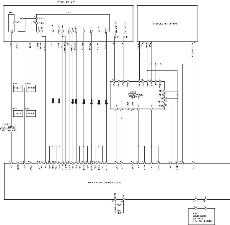
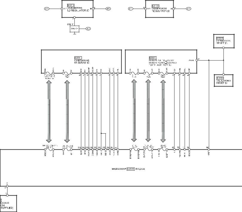
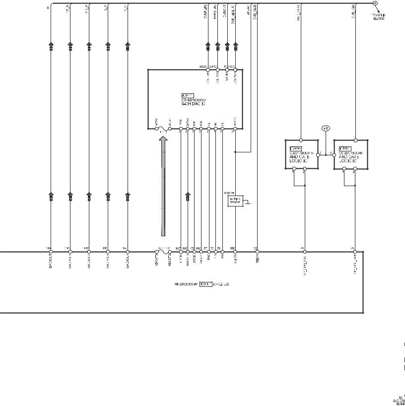
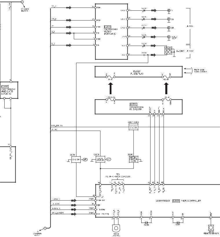
17 Block Diagram
75
manual de servicio SC-TM910DVD
76
manual de servicio SC-TM910DVD
77
manual de servicio SC-TM910DVD
78
manual de servicio SC-TM910DVD
79
manual de servicio SC-TM910DVD
80
manual de servicio SC-TM910DVD
 Loading...