


SCHT888
EJECT
/ I
FF
REV MODE
REW
REC
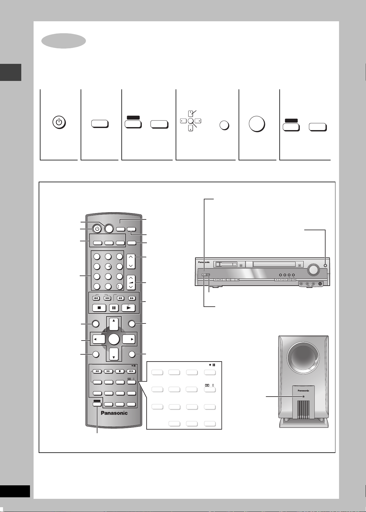
The illustration shows SC-HT623.
Operating Instructions
VOLUME
SELECTOR
OPEN/CLOSE
M.RE-MASTER
SFC
SW LEVEL
SURROUND
DOWN
UP
TUNE MODE FM MODE
KARAOKE
MEMORY
TUNING
MIN MAX
PHONES
12MIC MIC VOL
DVD Home Theater Sound System
Model No. SC-HT888/SC-HT623
Before connecting, operating or adjusting this product,
please read these instructions completely.
Please keep this manual for future reference.
Region number
The player plays DVD-Video marked with labels containing the
region number or “ALL”.
Region Number
United Arab Emirates 2
Southeast Asia and Singapore 3
Russia 5
Example: [Southeast]Asia]and]Singapore[
2
GCU
3
5
3 ALL
This manual was printed with soy based ink.
EE
GCS GCA
Table of contents
Getting started
Accessories . . . . . . . . . . . . . . . . . . . . . . . . . . . . . . 2
Safety precautions/Maintenance . . . . . . . . . . . . . 3
Glossary . . . . . . . . . . . . . . . . . . . . . . . . . . . . . . . . . 3
Simple setup
STEP 1 Front and surround speaker
STEP 2 Locating . . . . . . . . . . . . . . . . . . . . . . . 6
STEP 3 Connecting speakers with the
STEP 4 Video connections . . . . . . . . . . . . . . . 8
STEP 5 Radio and system connection . . . . . 9
STEP 6 The remote control. . . . . . . . . . . . . . . 9
STEP 7 QUICK SETUP. . . . . . . . . . . . . . . . . . 10
Control reference guide . . . . . . . . . . . . . . . . . . . 10
Discs that can be played/Disc handling . . . . . . 11
Disc operations
Basic play (DISC). . . . . . . . . . . . . . . . . . . . . . . . 12
Convenient functions . . . . . . . . . . . . . . . . . . . . . 14
Position memory/Zoom/Audio/Subtitle/Quick replay/
Page skip/A-B Repeat play/Repeat play/
All group, random and program play
Using navigation menus . . . . . . . . . . . . . . . . . . . 16
Playing data discs/Playing HighMATTM discs/Playing
the programs/Playing a play list
Using on-screen menus . . . . . . . . . . . . . . . . . . . 18
Changing the player settings . . . . . . . . . . . . . . . 20
Speaker Setting
Other operations
The radio. . . . . . . . . . . . . . . . . . . . . . . . . . . . . . . . 22
Automatic presetting/Selecting the preset channels/
Manual tuning/Optional antenna connections
Cassette tapes . . . . . . . . . . . . . . . . . . . . . . . . . . . 24
Basic play/Recording to cassette tapes
Karaoke Song Album—Unique functions
Enjoying other recording methods/
DVD/CD-TAPE mode
Sound field and sound quality . . . . . . . . . . . . 26-28
Sound Field Control/Super Surround/Center Focus/
Dolby Pro Logic II/Adjusting the speaker levels/Downmixing/Subwoofer level/Custom Sound Memory
Other functions . . . . . . . . . . . . . . . . . . . . . . . . . . 29
Sleep timer/Muting/Enjoying Karaoke/
Using headphones
Connecting to other equipment . . . . . . . . . . . . . 30
Reference
Language code list . . . . . . . . . . . . . . . . . . . . . . . 31
Specifications . . . . . . . . . . . . . . . . . . . . . . . . . . . 32
Troubleshooting guide . . . . . . . . . . . . . . . . . . . . 34
assembly. . . . . . . . . . . . . . . . . . . . . . . 4
Other speaker setup options . . . . . . 5
active subwoofer . . . . . . . . . . . . . . . . 7
RQTC0047-1B
Dear customer
Thank you for purchasing this product. For optimum performance
and safety, please read these instructions carefully.
[HT888]: indicates features applicable to SC-HT888 only.
[HT623]: SC-HT623 only.
≥These operating instructions are applicable to models
SC-HT888 and SC-HT623 for a variety of regions.
≥Unless otherwise indicated, illustrations in these
operating instructions are of SC-HT623 for Southeast
Asia and Singapore.
≥Operations in these instructions are described mainly
with the remote control, but you can do the operations on
System SC-HT888 SC-HT623
Main unit SA-HT888 SA-HT623
Front speakers SB-FS888 SB-FS623
Center speaker SB-PC888 SB-PC623
Surround speakers SB-FS888 SB-FS623
Active subwoofer SB-WA888 SB-WA623
the main unit if the controls are the same.
CAUTION!
THIS PRODUCT UTILIZES A LASER.
Accessories
USE OF CONTROLS OR ADJUSTMENTS OR PERFORMANCE
OF PROCEDURES OTHER THAN THOSE SPECIFIED HEREIN
MAY RESULT IN HAZARDOUS RADIATION EXPOSURE.
DO NOT OPEN COVERS AND DO NOT REPAIR YOURSELF.
REFER SERVICING TO QUALIFIED PERSONNEL.
The socket outlet shall be installed near the equipment and
easily accessible or the mains plug or an appliance coupler shall
remain readily operable.
This product may receive radio interference caused by mobile
telephones during use. If such interference is apparent, please
increase separation between the product and the mobile
telephone.
WARNING:
TO REDUCE THE RISK OF FIRE, ELECTRIC SHOCK OR
PRODUCT DAMAGE, DO NOT EXPOSE THIS APPARATUS
TO RAIN, MOISTURE, DRIPPING OR SPLASHING AND THAT
NO OBJECTS FILLED WITH LIQUIDS, SUCH AS VASES,
SHALL BE PLACED ON THE APPARATUS.
CAUTION!
≥DO NOT INSTALL OR PLACE THIS UNIT IN A BOOKCASE,
BUILT-IN CABINET OR IN ANOTHER CONFINED SPACE.
ENSURE THE UNIT IS WELL VENTILATED. TO PREVENT
RISK OF ELECTRIC SHOCK OR FIRE HAZARD DUE TO
OVERHEATING, ENSURE THAT CURTAINS AND ANY
OTHER MATERIALS DO NOT OBSTRUCT THE
VENTILATION VENTS.
≥DO NOT OBSTRUCT THE UNIT’S VENTILATION OPENINGS
WITH NEWSPAPERS, TABLECLOTHS, CURTAINS, AND
SIMILAR ITEMS.
≥DO NOT PLACE SOURCES OF NAKED FLAMES, SUCH AS
LIGHTED CANDLES, ON THE UNIT.
≥DISPOSE OF BATTERIES IN AN ENVIRONMENTALLY
FRIENDLY MANNER.
For Southeast Asia, Singapore and United Arab Emirates
THIS UNIT IS INTENDED FOR USE IN TROPICAL CLIMATES.
For Russia
THIS UNIT IS INTENDED FOR USE IN MODERATE CLIMATES.
CLASS 1
LASER PRODUCT
(For Southeast
Asia and
Singapore)
(Back of product)
(For Russia and United
Arab Emirates)
(Inside of product)
RQTC0047
2
For Southeast Asia, Singapore and United Arab Emirates
CAUTION:
The AC voltage is different according to the area. Be sure to set proper voltage in your area before use. (For details, please refer to page 9)
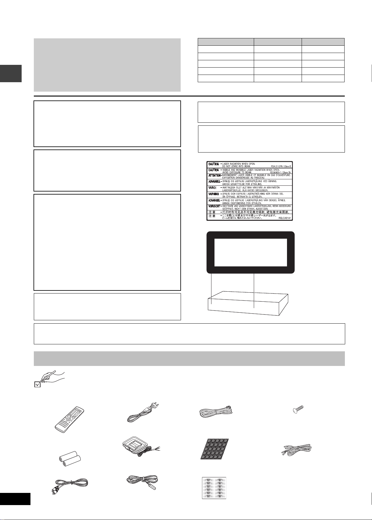
Accessories
Please check and identify the supplied accessories.
∏ 1 Remote control
(EUR7722060)
∏ 2 Remote control
batteries
∏ 1 Video cable
∏ 1 AC mains lead
∏ 1 AM loop antenna
∏ 1 FM indoor antenna
∏ 1 System cable
∏ 1 Sheet of rubber feet
[HT623]
∏ 1 Sheet of speaker-
cable stickers
SUBWOOFER
SUBWOOFER
6
6
6
6
SUBWOOFER
SUBWOOFER
CENTER
CENTER
5
5
5
5
CENTER
CENTER
SURROUND R
SURROUND R
4
4
4
4
SURROUND R
SURROUND R
SURROUND L
SURROUND L
3
3
3
3
SURROUND L
SURROUND L
FRONT R
FRONT R
2
2
2
2
FRONT R
FRONT R
FRONT L
FRONT L
1
1
1
1
FRONT L
FRONT L
∏ 12 Screws [HT888]
∏ Speaker cables
3k4-m cables
2k10-m cables
[Note]
The included AC mains lead is for use
with this unit only.
Do not use it with other equipment.

Safety precautions
Placement
Set the unit up on an even surface away from direct sunlight, high
temperatures, high humidity, and excessive vibration. These
conditions can damage the cabinet and other components, thereby
shortening the unit’s service life.
Do not place heavy items on the unit.
Voltage
Do not use high voltage power sources. This can overload the unit
and cause a fire.
Do not use a DC power source. Check the source carefully when
setting the unit up on a ship or other places where DC is used.
AC mains lead protection
Ensure the AC mains lead is connected correctly and not
damaged. Poor connection and lead damage can cause fire or
electric shock. Do not pull, bend, or place heavy items on the lead.
Grasp the plug firmly when unplugging the lead. Pulling the AC
mains lead can cause electric shock.
Do not handle the plug with wet hands. This can cause electric
shock.
Foreign matter
Do not let metal objects fall inside the unit. This can cause electric
shock or malfunction.
Do not let liquids get into the unit. This can cause electric shock or
malfunction. If this occurs, immediately disconnect the unit from the
power supply and contact your dealer.
Do not spray insecticides onto or into the unit. They contain
flammable gases which can ignite if sprayed into the unit.
Service
Do not attempt to repair this unit by yourself. If sound is
interrupted, indicators fail to light, smoke appears, or any other
problem that is not covered in these instructions occurs, disconnect
the AC mains lead and contact your dealer or an authorized service
center. Electric shock or damage to the unit can occur if the unit is
repaired, disassembled or reconstructed by unqualified persons.
Extend operating life by disconnecting the unit from the power
source if it is not to be used for a long time.
Glossary
Decoder
A decoder restores the coded audio signals on DVDs to normal. This
is called decoding.
Dolby Digital
This is a method of coding digital signals developed by Dolby
Laboratories. Apart from stereo (2-channel) audio, these signals can
also be multi-channel audio. A large amount of audio information can
be recorded on one disc using this method.
DTS (Digital Theater Systems)
This surround system is used in many movie theaters around the
world. There is good separation between the channels, so realistic
sound effects are possible.
Dynamic range
Dynamic range is the difference between the lowest level of sound
that can be heard above the noise of the equipment and the highest
level of sound before distortion occurs.
Frame still and field still
Frames are the still pictures that go together to make a moving
picture. There are about 30 frames shown each second.
One frame is made up of two fields. A regular television shows these
fields one after the other to create frames.
A still is shown when you pause a moving picture. A frame still is
made up of two alternating fields, so the picture may appear blurred,
but overall quality is high.
A field still is not blurred, but it has only half the information of a
frame still so picture quality is lower.
I/P/B
MPEG 2, the video compression standard adopted for use with
DVD-Video, codes frames using these 3 picture types.
I: Intra coded picture
This picture has the best quality and is the best to use when
adjusting the picture.
P: Predictive coded picture
This picture is calculated based on past I or P-pictures.
B: Bidirectionally-predictive coded picture
This picture is calculated by comparing past and future I and
P-pictures so it has the lowest volume of information.
Linear PCM (pulse code modulation)
These are uncompressed digital signals, similar to those found on
CDs.
Playback control (PBC)
If a Video CD has playback control, you can select scenes and
information with menus.
Safety precautions/Maintenance/Glossary
Maintenance
Clean this unit with a soft, dry cloth.
≥Never use alcohol, paint thinner or benzine to clean this unit.
≥Before using chemically treated cloth, read the instructions that
came with the cloth carefully.
Before moving the unit, ensure the disc tray is empty.
Failure to do so will risk severely damaging the disc and the
unit.
For a cleaner crisper sound
Clean the heads regularly to assure good quality playback and
recording.
Use a cleaning tape (not included).
Sampling frequency
Sampling is the process of converting the heights of sound wave
(analog signal) samples taken at set periods into digits (digital
encoding). Sampling frequency is the number of samples taken per
second, so larger numbers mean more faithful reproduction of the
original sound.
RQTC0047
3
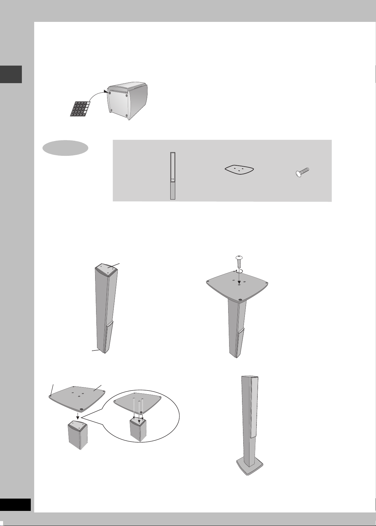
Simple setup
Preparation
[HT623] (Front and surround speakers only)
Attach the rubber feet to prevent vibration causing the speakers to move or fall over.
Use 3 or 4 feet per speaker.
Make sure you have all the indicated components before starting the assembly, setup, and
STEP
1
connection.
4 speaker boxes
4 bases
[HT888]
Front and surround speaker assembly
12 screws
Front and surround speaker assembly
Preparation
≥To prevent damage or scratches, lay a soft cloth and perform assembly on it.
≥For assembly, use a Phillips-head screwdriver.
1 Reverse the speaker box.
Bottom of the speaker
box
Top of the speaker box
2 Place the base on the bottom of the
speaker box.
Rubber feet
Base
3 Secure the base to the speaker box.
4 Reverse the assembled speaker.
Ensure the base is fastened
on straight by lightly tightening
the 3 screws alternately until
fully tightened.
RQTC0047
4
3 holes in the base should be aligned
to those in the speaker.
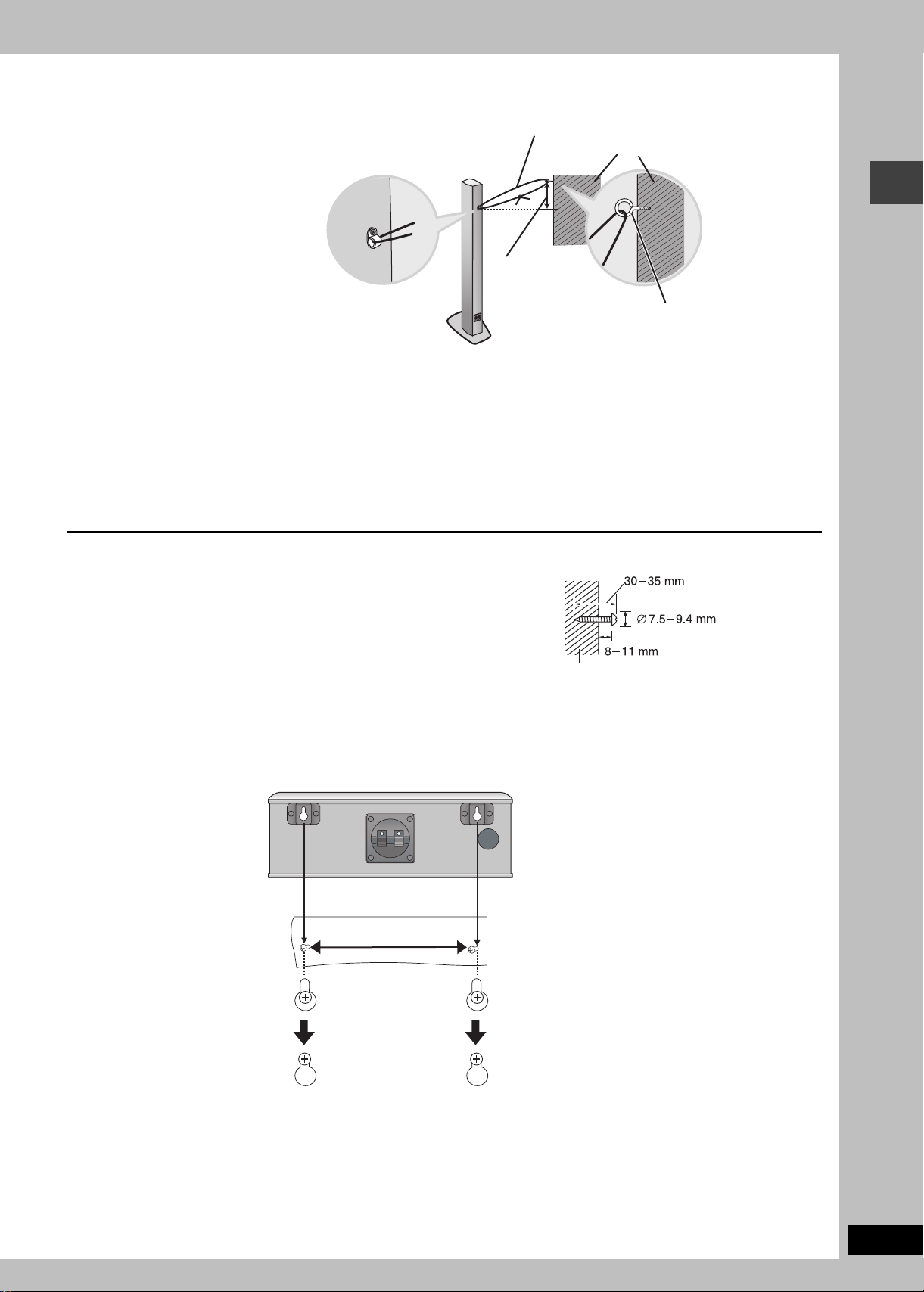
∫ Preventing the front and surround speakers from falling over
P
reparation
≥You will need to obtain the appropriate screw eyes to match the
walls to which the screw eyes are going to be fastened.
≥The walls should be capable of supporting 30 kg per screw.
[Note]
Consult with a qualified housing contractor concerning the appropriate procedure when attaching to a concrete wall or a surface that may not
have strong enough support. Improper attachment may result in damage to the wall or speakers.
String (not included)
Wall
Approx. 150 mm
Screw eye (not included)
Other speaker setup options
[HT888] (Center speaker only) [HT623]
∫ Attaching to a wall
1 Drive a screw (not included) into a wall.
2 Fit the speaker securely onto the screw(s) with the hole(s).
≥The wall or pillar on which the speakers are to be attached should be capable of
supporting 10 kg per screw. Consult a qualified building contractor when attaching the
speakers to a wall. Improper attachment may result in damage to the wall and speakers.
e.g. Center speaker [HT888] [HT623]
200 mm
Wall or pillar
Front and surround speaker assembly/Other speaker setup options
RQTC0047
5
ff
STEP
2
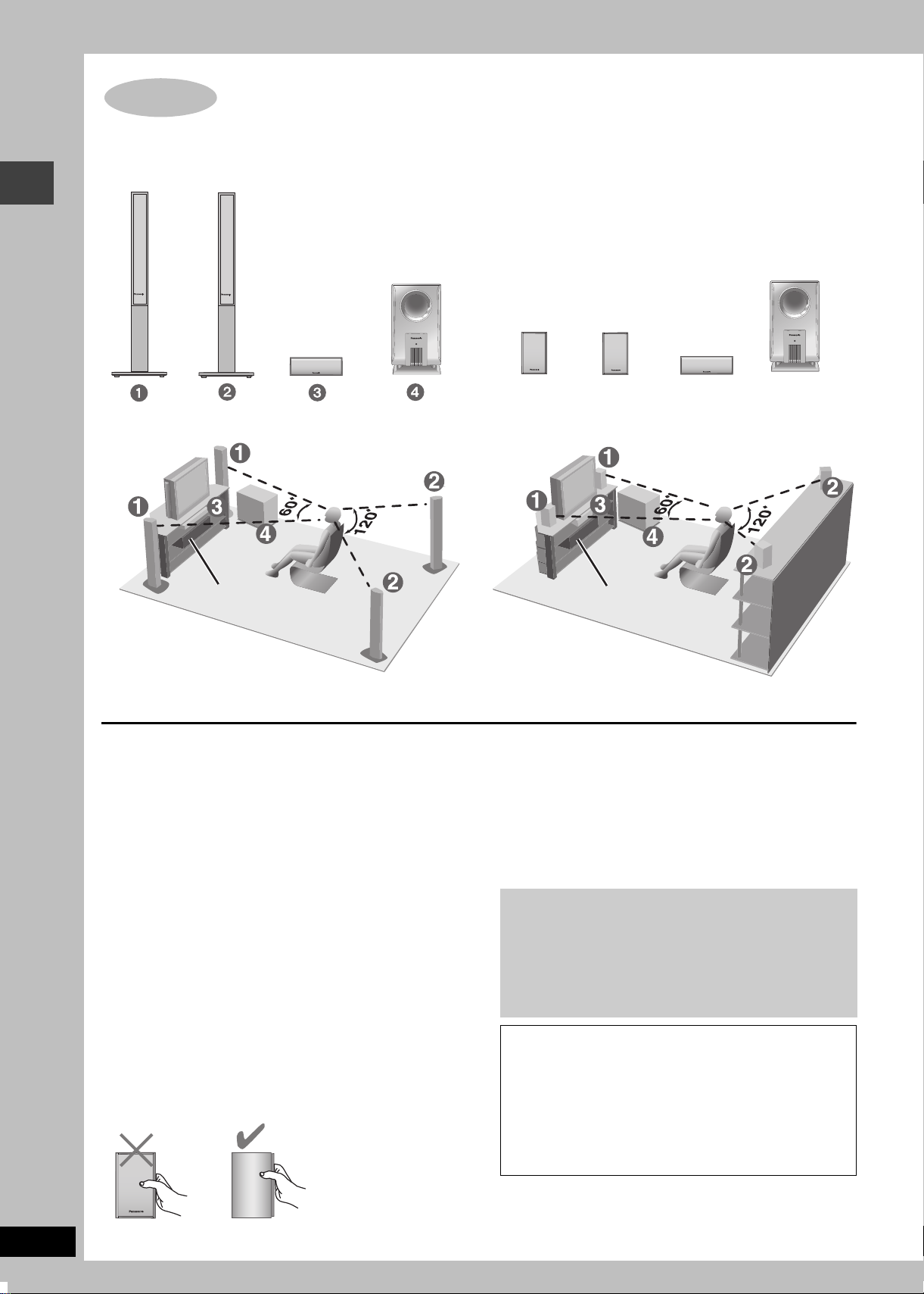
Locating
How you set up your speakers can a
≥Place speakers on flat secure bases.
≥Placing speakers too close to floors, walls, and corners can result in excessive bass. Cover
walls and windows with thick curtains.
≥Place the front, center, and surround speakers at approximately the same distance from the
seating position. The angles in the diagrams are approximate.
ect the bass and the sound field. Note the following points.
[HT888]
[HT623]
Locating
4
ACTIVE
SUBWOOFER
FRONT
(L, R)
Setup example
SURROUND
(L, R)
Main unit
CENTER
ACTIVE
SUBWOOFER
12 3
FRONT
(L, R)
Setup example
SURROUND
(L, R)
Main unit
CENTER
≥The left and right front, and left and right surround speakers are all identical.
≥Use only supplied speakers
Using other speakers can damage the unit and sound quality will
be negatively affected.
≥Set the speakers up on an even surface to prevent them from
falling. Take proper precautions to prevent the speakers from
falling if you cannot set them up on an even surface.
Main unit
[Note]
Keep your speakers at least 10 cm away from the main unit for
proper ventilation.
Center speaker
≥Vibration caused by the center speaker can disrupt the picture if it
is placed directly on the television. Put the center speaker on a
rack or shelf.
≥To prevent the speakers from falling, do not place directly on top
of the television.
Active subwoofer
Place to the right or left of the television, on the floor or a sturdy
shelf so that it won’t cause vibration. Leave 10 cm at the rear for
ventilation.
Caution
Hold the speakers by the sides. Applying pressure to the front net
can damage the speaker.
e.g. [HT623]
Notes on speaker use
≥You can damage your speakers and shorten their useful life if you
play sound at high levels over extended periods.
≥Reduce the volume in the following cases to avoid damage.
– When playing distorted sound.
– When the speakers are receiving howling from a record player,
noise from FM broadcasts, or continuous signals from an
oscillator, test disc, or electronic instrument.
– When adjusting the sound quality.
– When turning the unit on or off.
If irregular coloring occurs on your television
The supplied speakers are designed to be used close to a
television, but the picture may be affected with some televisions
and setup combinations.
If this occurs, turn the television off for about 30 minutes.
The television’s demagnetizing function should correct the
problem. If it persists, move the speakers farther away from the
television.
Caution
≥The main unit and supplied speakers are to be used only
as indicated in this setup. Failure to do so may lead to
damage to the amplifier and/or the speakers, and may
result in the risk of fire. Consult a qualified service
person if damage has occurred or if you experience a
sudden change in performance.
≥Do not attempt to attach these speakers to walls using
methods other than those described in this manual.
RQTC0047
6
STEP
3
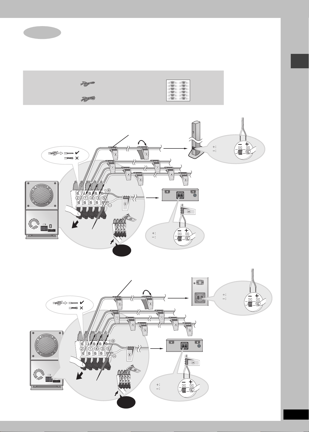
Connecting speakers with the active subwoofer
Attach the speaker-cable stickers to make connection easier.
\Note]
≥Never short-circuit positive (i) and negative (j) speaker wires.
≥Be sure to connect only positive (copper) wires to positive (i) terminals and negative (silver) wires to negative (j) terminals.
Incorrect connection can damage the speakers.
5 speaker cables
≥3k4-m cables: For front and center speakers
≥2k10-m cables: For surround speakers
Sheet of speaker-cable stickers
SUBWOOFER
SUBWOOFER
6
6
6
6
SUBWOOFER
SUBWOOFER
CENTER
CENTER
5
5
5
5
CENTER
CENTER
SURROUND R
SURROUND R
4
4
4
4
SURROUND R
SURROUND R
SURROUND L
SURROUND L
3
3
3
3
SURROUND L
SURROUND L
FRONT R
FRONT R
2
2
2
2
FRONT R
FRONT R
FRONT L
FRONT L
1
1
1
1
FRONT L
FRONT L
[HT888]
Speaker-cable sticker
ACTIVE
SUBWOOFER
[HT623]
Insert the wire fully.
Click!
2 FRONT (R)
5 CENTER
Copper
Silver
Speaker-cable sticker
Copper
Silver
1 FRONT (L)
4 SURROUND (R)
3 SURROUND (L)
Connecting speakers with the active subwoofer
ACTIVE
SUBWOOFER
Insert the wire fully.
Click!
2 FRONT (R)
1 FRONT (L)
5 CENTER
Copper
Silver
Copper
Silver
4 SURROUND (R)
3 SURROUND (L)
RQTC0047
7
STEP
4
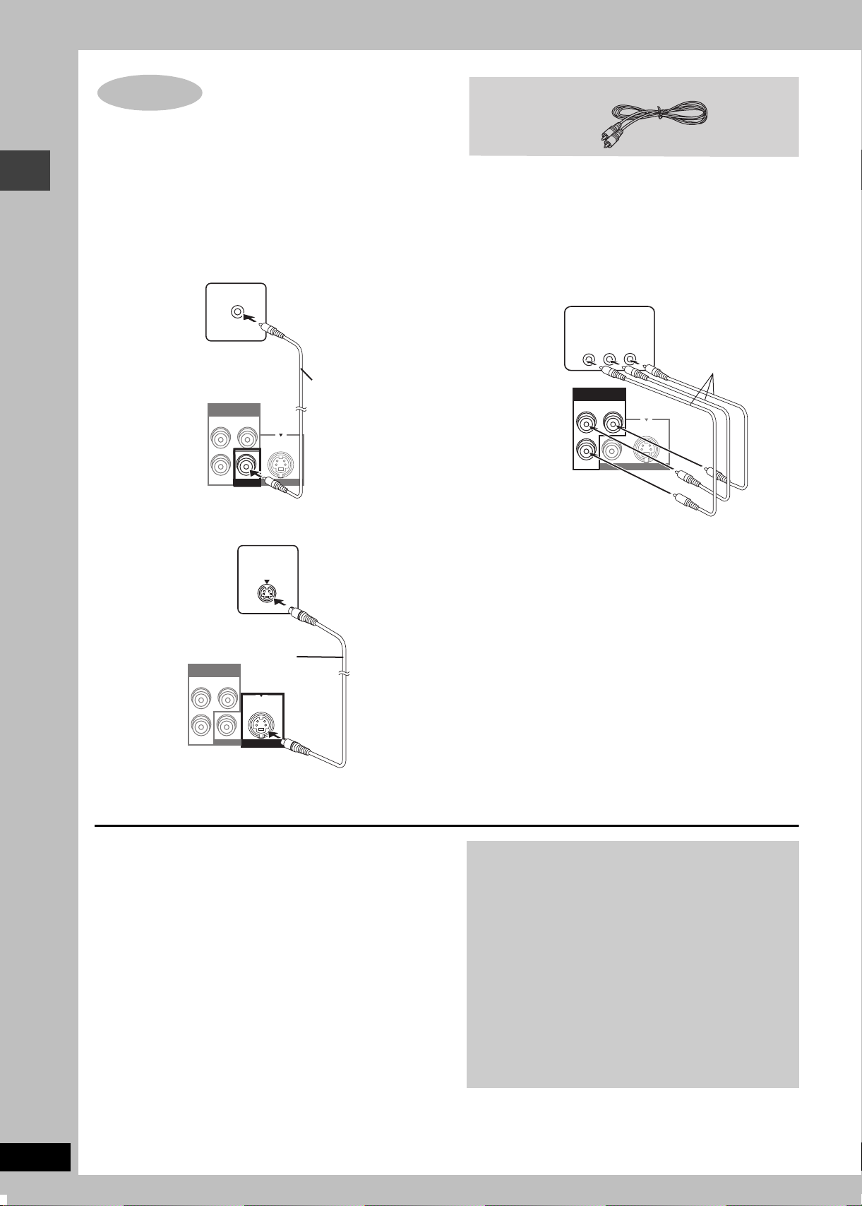
Video connections
≥Do not connect through the video cassette recorder.
Due to copy guard protection, the picture may not display
properly.
≥Turn the television off before connecting, and refer to the
television’s operating instructions.
Video cable
Video connections
∫ Television with a VIDEO IN terminal
Television
(not included)
Back of the
main unit
VIDEO IN
COMPONENT VIDEO OUT
(NTSC:480p/480i.PAL:576i)
P
B
P
R
VIDEO OUT
Y
Please connect
directly toTV
S VIDEO OUT
Video cable
(included)
∫ Television with an S-VIDEO IN terminal
Television
(not included)
Back of the
main unit
COMPONENT VIDEO OUT
(NTSC:480p/480i.PAL:576i)
P
B
S-VIDEO
IN
S-video cable
(not included)
Y
Please connect
directly toTV
∫ Television with COMPONENT VIDEO IN
terminals
Television
(not included)
Back of the
main unit
COMPONENT
VIDEO IN
PR
PB
COMPONENT VIDEO OUT
(NTSC:480p/480i.PAL:576i)
P
B
Y
P
R
VIDEO OUT
Y
Please connect
directly toTV
S VIDEO OUT
Video cables
(not included)
RQTC0047
8
P
R
VIDEO OUT
S VIDEO OUT
S VIDEO OUT terminal
The S VIDEO OUT terminal achieves a more vivid picture than the
VIDEO OUT terminal by separating the chrominance (C) and
luminance (Y) signals. (Actual results depend on the television.)
COMPONENT VIDEO OUT terminals
These terminals can be used for either interlace or progressive
output and provide a purer picture than the S VIDEO OUT
terminal. Connection using these terminals outputs the color
difference signals (P
B/PR) and luminance signal (Y) separately in
order to achieve high fidelity in reproducing colors.
≥The description of the component video input terminals depends
on the television or monitor (e.g. Y/P
B/PR, Y/B-Y/R-Y, Y/CB/CR).
Connect to terminals of the same color.
To enjoy progressive video
Connect to the component video input terminals on a 480P
compatible television. (Video will not be displayed correctly if
connected to an incompatible television.)
≥Select “Enable (NTSC Disc Only)” in the progressive output
setting in QUICK SETUP (➜ page 10). Then play an NTSC
disc.
≥When playing NTSC discs, change video output mode to
“480P” (➜ page 19) so “PROG.” appears on the display.
All Panasonic televisions that have 480P input connectors are
compatible. Consult the manufacturer if you have another
brand of television.
[Note]
Output from this unit is interlace if you have connected to the
television through the VIDEO OUT or S VIDEO OUT terminal
or when playing PAL discs, even if “PROG.” is on the display.
STEP
A
LINE
OUTTVAUDIO
IN
VCR/
AUX
IN
P
B
P
R
FM ANT
AM ANT
LOOP
EXT
SIGNAL EARTH
(75
)
L
R
COMPON
(NTSC:480
5
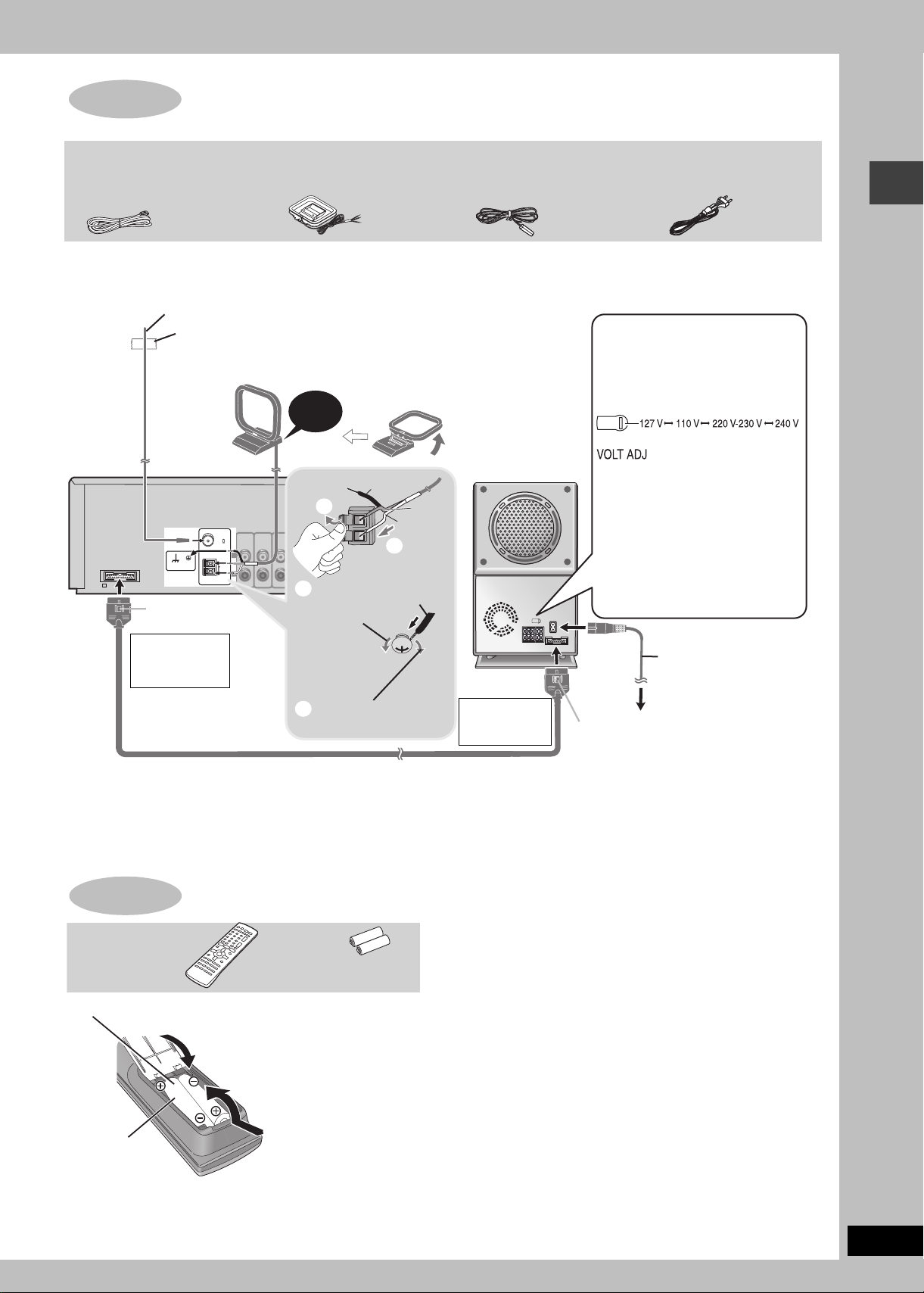
Radio and system connection
System cable
AM loop
antenna
≥Connect the AC mains lead after all other connections are complete.
≥Optional antenna connections (➜ page 23).
FM indoor antenna
AM loop antenna
Stand the antenna up on its base.
Place the antenna where the
reception is best.
Keep loose antenna cable away from
other wires and cables.
Black
Red
White
2
Black
Main unit
Adhesive tape
Fix the other end of the antenna
where reception is best.
FM ANT
(75
)
L
SIGNAL EARTH
AM ANT
LOOP
EXT
R
Catch up
Click!
1
Loosen with a
3
Phillips-head
screwdriver.
FM indoor
antenna
Active
subwoofer
AC mains lead
\Southeast\Asia,\Singapore]and]United[
[Arab\Emirates]
Before connecting the
AC mains lead
Set the voltage.
Use a flat-head screwdriver to turn
the voltage selector on the back of
the active subwoofer to the
appropriate position for the area in
which this system is used.
If the power supply in your area is
115 V or 120 V, please set the voltage
selector as follows:
≥For 115 V: Set to 110 V.
≥For 120 V: Set to 127 V.
Radio and system connection/The remote control
To disconnect
Press the catch
AC mains lead
and pull out.
To household mains socket
System cable
Tighten again.
4
To disconnect
Press the catch
and pull out.
Catch up
Conserving power
The main unit consumes a small amount of power, even when it is turned off (approx. 1 W). To save power when the unit is not to be used for
a long time, unplug it from the household mains socket.
You will need to reset some memory items after plugging in the unit.
STEP
Remote control
6
The remote control
Batteries
Do not:
≥mix old and new batteries.
≥use different types at the same time.
≥heat or expose to flame.
Insert so the poles (i and j) match
2
those in the remote control.
3
≥take apart or short circuit.
≥attempt to recharge alkaline or manganese batteries.
≥use batteries if the covering has been peeled off.
Mishandling of batteries can cause electrolyte leakage which can
damage items the fluid contacts and may cause a fire.
Remove if the remote control is not going to be used for a long
period of time. Store in a cool, dark place.
∫ Use
R6/LR6, AA, UM-3
1
≥Do not use
rechargeable type
batteries.
Aim at the sensor (➜ page 10), avoiding obstacles, at a maximum
range of 7 m directly in front of the unit.
RQTC0047
9
STEP
7
QUICK SETUP
The QUICK SETUP screen assists you to make necessary settings.
Turn on the television and select the appropriate video input on the television.
123 4 56
QUICK SETUP/Control reference guide
DVD/CD
SHIFT
r
Turn the unit
on.
To change these settings later
Select “QUICK SETUP” in “Others” tab (➜ page 21).
Select
“DVD/CD”.
Shows QUICK
SETUP screen.
Control reference guide
See reference pages in brackets.
(29)
Turn the unit
on/off.
Select the source
(10, 22, 24, 30).
(13)
(13, 16, 17)
DIRECT NAVIGATOR
(10)
(13, 18)
SLEEP
VCR/AUX
TV
TUNER/BAND
TAP E
123
45 6
7809
CANCEL
SKIP
STOP DVD/CDPAU S E
TOP MENU
ENTER
DISPLAY
FF STOPREW
C.S.M
REV MODE
SFC
POSITION
SUBWOOFER
LEVEL
MEMORY
TEST
SHIFT
CH SELECT
ECHO
KARAOKE
FL DISPLAY
DVD/CD MUTING
CH
VOLUME
10
SLOW/SEARCH
MENU
PLAY LIST
RETURN
PAG EGROUP
REC /
TAP E
C.FOCUS
MIX 2CH
SUPER SRND
PL
ZOOM
SUBTITLE
AUDIO
QUICK REPLAY
REPEAT
SETUP
A-B REPEAT
PLAY MODE
(12)
(13, 16, 17)
SETUP
PLAY MODE
Select
ENTER
Register
Follow the messages
and make the settings.
(13)
(29)
(29)
(22)
Adjust the volume.
(13, 14)
REW
FF
STOP
(24) (24) (24)
C.S.M
REV MODE
(24)
SUBWOOFER
LEVEL
(26, 28)
SFC
POSITION
MEMORY
C.FOCUS
SUPER SRND
(26)
ZOOM
AUDI O
(28) (14) (14) (14)
TEST
CH SELECT
(27) (
REPEAT
A-B REPEAT
14,15)(15, 20)
RETURN
ENTER
Press to
SHIFT
Press to exit.
finish QUICK
SETUP.
Standby/on indicator
When the unit is connected to the AC mains
supply, this indicator lights red in standby mode
and lights green when the unit is turned on.
Source select button [SELECTOR] (22)
DVD/CD
# TA P E # FM # AM # TV
# VCR/AUX # Return to DVD/CD
EJECT
M.RE-MASTER
SFC
SW LEVEL
/ I
FF
REV MODE
REW
REC
TUNE MODE FM MODE
SURROUND
MEMORY
TUNING
Remote control signal sensor
Standby/on switch [Í/I]
Press to switch the unit from on to standby mode or
vice versa.
In standby mode, the unit is still consuming a small
amount of power.
REC /
TA PE
(24, 25)
MIX 2CH
PL
(26, 28)
SUBTITLE
QUICK REPLAY
SETUP
PLAY MODE
AC supply
indicator (AC IN)
This indicator lights
when the unit is
connected to the AC
mains supply.
r
OPEN/CLOSE
PHONES
SETUP
PLAY MODE
VOLUME
SELECTOR
DOWN
UP
KARAOKE
MIN MAX
12MIC MIC VOL
RQTC0047
10
To use functions labeled in orange:
While pressing [SHIFT], press the corresponding button.

Discs that can be played
Disc Logo
DVD-RAM
DVD-Audio
DVD-V ideo
Indication
used in
operating
instructions
[RAM]
[JPEG]
[DVD-A] —
[DVD-V]
Remarks
Recorded using Version 1.1 of the
Video Recording Format (a unified
video recording standard).
Recorded using the DCF (Design
rule for Camera File system)
standard.
Some DVD-Audio discs contain DVD-Video content.
To play DVD-Video content, select “Play as DVD-Video” in Other Menu (➜ page 19)
—
≥Recorded with DVD-Video recorders, DVD-
Video cameras, personal computers, etc.
≥Remove TYPE 2
and 4 discs from
their cartridges
before use.
≥Recorded with Panasonic DVD-Video
recorders.
≥To play JPEG files, select “Play as Data Disc”
in Other Menu (➜ page 19).
[DVD-V]
DVD-R
Video CD
[VCD]
SVCD
CD [CD]
[WMA]
CD-R
CD-RW
§
A process that allows play on compatible equipment.
≥It may not be possible to play the above discs in all cases due to the type of disc or condition of the recording.
—
[MP3]
[JPEG]
[CD]
[VCD]
Panasonic DVD-R recorded and finalized
DVD-Video cameras are played as DVD-Video on this unit.
—
Conforming to IEC62107
This unit is compatible with HDCD, but does not support the Peak Extend function.
(A function which expands the dynamic range of high level signals)
HDCD-encoded CDs sound better because they are encoded with 20 bits, as
compared with 16 bits for all other CDs.
≥During HDCD play, “HDCD” lights on the unit’s display.
≥This unit can play CD-R/RW (audio recording disc) recorded with the formats on
the left. Close the sessions or finalize
≥HighMAT discs
WMA, MP3 or JPEG files only.
To play without using the HighMAT function, select “Play as Data Disc” in Other
Menu (➜ page 19).
§
on Panasonic DVD-Video recorders or
§
the disc after recording.
∫ Discs that cannot be played
DVD-ROM, CD-ROM, CDV, CD-G, DVD+R, iRW, DVD-RW, SACD,
Divx Video Discs and Photo CD, DVD-RAM that cannot be removed
from their cartridge, 2.6-GB and 5.2-GB DVD-RAM, and “Chaoji
VCD” available on the market including CVD, DVCD and SVCD that
do not conform to IEC62107.
Disc handling
∫ To clean discs
[DVD-A] [DVD-V] [VCD] [CD]
Wipe with a damp cloth and then wipe dry.
∫ Audio format of DVDs
This unit automatically recognizes
and decodes discs with these
symbols.
Discs that can be played/Disc handling
∫ Video systems
– This unit can play PAL and NTSC, but your television must match
the system used on the disc.
– PAL discs cannot be correctly viewed on an NTSC television.
– This unit can convert NTSC signals to PAL 60 for viewing on a PAL
television (➜ page 20, “NTSC Disc Output” in “Video” tab).
HighMAT™ and the HighMAT logo are either
trademarks or registered trademarks of
Microsoft Corporation in the United States
and/or other countries.
[RAM] [DVD-R]
≥Clean with an optional DVD-RAM/PD disc cleaner
(LF-K200DCA1, where available).
≥Never use cloths or cleaners for CDs, etc.
∫ Disc handling precautions
≥Do not attach labels or stickers to discs (This may cause disc
warping, rendering it unusable).
≥Do not write on the label side with a ball-point pen or other writing
instrument.
≥Do not use record cleaning sprays, benzine, thinner, static
electricity prevention liquids or any other solvent.
≥Do not use scratch-proof protectors or covers.
≥Do not use the following discs:
– Discs with exposed adhesive from removed stickers or labels
(rented discs, etc.).
– Discs that are badly warped or cracked.
– Irregularly shaped discs, such as heart shapes.
RQTC0047
11
 Loading...