


Recordable DVD Home Theater System
Operating Instructions
Model No. SC-RT30
SC-RT70
Operations Guide
Before using this product, perform setup and connections after carefully reading the Setup Guide.
The illustration shows SC-RT30.
Region number supported by this unit
Region numbers are allocated to DVD players and DVD-Video according to where they are sold.
≥The region number of this unit is “2”. ≥The unit will play DVD-Video marked with
labels containing “2” or “ALL”.
Example:
2 ALL 235
Dear customer
Thank you for purchasing this product. For optimum performance and safety, please read these instructions carefully.
Before connecting, operating or adjusting this product, please read the instructions completely. Please keep this manual for future reference.
These operating instructions are applicable to the following system.
System |
SC-RT30 |
SC-RT70 |
|
This unit |
SA-RT30 |
SA-RT70 |
|
|
|
|
|
Front |
SB-FS440 |
SB-FS71 |
|
speakers |
|||
|
|
||
|
|
|
|
Center |
SB-PC640 |
SB-PC740 |
|
speaker |
|||
|
|
||
|
|
|
|
Surround |
SB-FS441 |
SB-FS72 |
|
speakers |
|||
|
|
||
|
|
|
|
Subwoofer |
SB-W440 |
SB-W940 |
|
|
|
|
About descriptions in these operating instructions
≥These operating instructions are applicable to models SC-RT30 and SC-RT70. Unless otherwise indicated, illustrations in these
operating instructions are of SC-RT30. [RT30] :indicates features applicable to
SC-RT30 only.
[RT70] :indicates features applicable to SC-RT70 only.
≥Pages to be referred to are indicated as “ {{”.
]Note]
“EB” on the outer packaging indicates the United Kingdom.
|
|
EB |
Web Site: http://www.panasonic-europe.com |
RQT8672-1B |
|
||||
|
|
|
|
|
|
|
|
|
|

Caution for AC Mains Lead
(For United Kingdom)
(“EB” area code model only)
For your safety, please read the following text carefully. This appliance is supplied with a moulded three pin mains plug for your safety and convenience.
A 5-ampere fuse is fitted in this plug.
Should the fuse need to be replaced please ensure that the replacement fuse has a rating of 5-ampere and that it is approved by ASTA or BSI to BS1362.
Check for the ASTA mark Ï or the BSI mark Ì on the body of the fuse.
If the plug contains a removable fuse cover you must ensure that it is refitted when the fuse is replaced.
If you lose the fuse cover the plug must not be used until a replacement cover is obtained.
A replacement fuse cover can be purchased from your local dealer.
CAUTION!
IF THE FITTED MOULDED PLUG IS UNSUITABLE FOR THE SOCKET OUTLET IN YOUR HOME THEN THE FUSE SHOULD BE REMOVED AND THE PLUG CUT OFF AND DISPOSED OF SAFELY.
THERE IS A DANGER OF SEVERE ELECTRICAL SHOCK IF THE CUT OFF PLUG IS INSERTED INTO ANY 13-AMPERE SOCKET.
If a new plug is to be fitted please observe the wiring code as stated below.
If in any doubt please consult a qualified electrician.
IMPORTANT
The wires in this mains lead are coloured in accordance with the following code:
Blue: Neutral, Brown: Live.
As these colours may not correspond with the coloured markings identifying the terminals in your plug, proceed as follows:
The wire which is coloured Blue must be connected to the terminal which is marked with the letter N or coloured Black or Blue.
The wire which is coloured Brown must be connected to the terminal which is marked with the letter L or coloured Brown or Red.
WARNING: DO NOT CONNECT EITHER WIRE TO THE EARTH TERMINAL WHICH IS MARKED WITH THE LETTER E, BY THE EARTH SYMBOL Ó OR COLOURED
GREEN OR GREEN/YELLOW.
THIS PLUG IS NOT WATERPROOF—KEEP DRY.
Before use
Remove the connector cover.
How to replace the fuse
The location of the fuse differ according to the type of AC mains plug (figures A and B). Confirm the AC mains plug fitted and follow the instructions below.
Illustrations may differ from actual AC mains plug.
1. Open the fuse cover with a screwdriver.
Figure A |
Figure B |
Fuse cover
2. Replace the fuse and close or attach the fuse cover.
Figure A |
Fuse |
Figure B |
Fuse |
|
(5 ampere) |
|
(5 ampere) |
RQT8672
2
CAUTION!
THIS PRODUCT UTILIZES A LASER.
USE OF CONTROLS OR ADJUSTMENTS OR PERFORMANCE OF PROCEDURES OTHER THAN THOSE SPECIFIED HEREIN MAY RESULT IN HAZARDOUS RADIATION EXPOSURE.
DO NOT OPEN COVERS AND DO NOT REPAIR YOURSELF. REFER SERVICING TO QUALIFIED PERSONNEL.
WARNING:
TO REDUCE THE RISK OF FIRE, ELECTRIC SHOCK OR PRODUCT DAMAGE, DO NOT EXPOSE THIS APPARATUS TO RAIN, MOISTURE, DRIPPING OR SPLASHING AND THAT NO OBJECTS FILLED WITH LIQUIDS, SUCH AS VASES, SHALL BE PLACED ON THE APPARATUS.
CAUTION!
≥DO NOT INSTALL OR PLACE THIS UNIT IN A BOOKCASE,
BUILT-IN CABINET OR IN ANOTHER CONFINED SPACE. ENSURE THE UNIT IS WELL VENTILATED. TO PREVENT RISK OF ELECTRIC SHOCK OR FIRE HAZARD DUE TO OVERHEATING, ENSURE THAT CURTAINS AND ANY OTHER MATERIALS DO NOT OBSTRUCT THE VENTILATION VENTS.
≥DO NOT OBSTRUCT THE UNIT’S VENTILATION
OPENINGS WITH NEWSPAPERS, TABLECLOTHS, CURTAINS, AND SIMILAR ITEMS.
≥DO NOT PLACE SOURCES OF NAKED FLAMES,
SUCH AS LIGHTED CANDLES, ON THE UNIT. ≥DISPOSE OF BATTERIES IN AN
ENVIRONMENTALLY FRIENDLY MANNER.
THIS UNIT IS INTENDED FOR USE IN MODERATE CLIMATES. ( 67, Specifications–GENERAL)
This product may receive radio interference caused by mobile telephones during use. If such interference is apparent, please increase separation between the product and the mobile telephone.
The socket outlet shall be installed near the equipment and easily accessible or the mains plug or an appliance coupler shall remain readily operable.
AV1
AV2
(Back of product)
(Inside of product)

Table of contents
Getting started
Caution for AC Mains Lead . . . . . . . . . . . . . . . . . . . . . . . .2 Accessories/The remote control information . . . . . . . . .4 Control reference guide . . . . . . . . . . . . . . . . . . . . . . . . . . .5
Disc information . . . . . . . . . . . . . . . . . . . . . . . . . . . . . . . . .6 STEP 1 Front and surround speaker assembly [RT70]. . 8
STEP 2 Positioning and connection of speakers . . . . .10 STEP 3 Video connections . . . . . . . . . . . . . . . . . . . . . . .12 STEP 4 Radio and AC mains lead connections . . . . . . .16 Speaker installation options . . . . . . . . . . . . . . . . . . . . . .17 TV Tuning (Auto Setup) . . . . . . . . . . . . . . . . . . . . . . . . . .18 Set up to match your television and remote control. . .20
Recording
Important notes for recording . . . . . . . . . . . . . . . . . . . . .22
Recording modes and approximate recording times . . .23 Disc Insertion/Ejection . . . . . . . . . . . . . . . . . . . . . . . . . .23
Recording television programmes . . . . . . . . . . . . . . . . .24
To specify a time to stop recording
—One Touch Recording . . . . . . . . . . . . . . . . . . . . . . .25 Flexible Recording . . . . . . . . . . . . . . . . . . . . . . . . . . . . .25 Playing while you are recording . . . . . . . . . . . . . . . . . . .25 Using another source while recording . . . . . . . . . . . . . .25
Timer recording . . . . . . . . . . . . . . . . . . . . . . . . . . . . . . . .26
Using VIDEO Plusr system to make timer recordings. .26 Manually programming timer recordings . . . . . . . . . . . .27 To cancel recording when recording has already begun. . .27 To release the programme from recording standby . . . .27 Notes on timer recording . . . . . . . . . . . . . . . . . . . . . . . .27 Check, change or delete a programme . . . . . . . . . . . . .28 Making timer recordings on the television . . . . . . . . . . .28
Recording from a satellite/digital terrestrial receiver . .29
Manual Recording . . . . . . . . . . . . . . . . . . . . . . . . . . . . .29 Linked timer recordings with external equipment (SKY
Digital STB/digital terrestrial receiver) — EXT LINK . .29
Playing back
Playing discs. . . . . . . . . . . . . . . . . . . . . . . . . . . . . . . . . . .30
Selecting recorded programmes (titles) to play
—Direct Navigator . . . . . . . . . . . . . . . . . . . . . . . . . . . .30 Changing audio during play . . . . . . . . . . . . . . . . . . . . . .30 Operations during play . . . . . . . . . . . . . . . . . . . . . . . . . .31
Using menus to play MP3 and still pictures (JPEG/TIFF). .32
Selecting file type to play . . . . . . . . . . . . . . . . . . . . . . . .32 Playing MP3 and still pictures (JPEG/TIFF). . . . . . . . . .32 To select other folder (group). . . . . . . . . . . . . . . . . . . . .33 Useful functions during still picture play . . . . . . . . . . . . .33 Regarding MP3 and still pictures . . . . . . . . . . . . . . . . . .34
Using on-screen menus/FUNCTIONS window
and Status message. . . . . . . . . . . . . . . . . . . . . . . . . . . .35
Using on-screen menus . . . . . . . . . . . . . . . . . . . . . . . . .35 FUNCTIONS window . . . . . . . . . . . . . . . . . . . . . . . . . . .36 Status message . . . . . . . . . . . . . . . . . . . . . . . . . . . . . . .36
Editing & Copying
Deleting titles . . . . . . . . . . . . . . . . . . . . . . . . . . . . . . . . . .37
Using DELETE Navigator to delete titles . . . . . . . . . . . .37 Deleting titles during play . . . . . . . . . . . . . . . . . . . . . . . .37
Editing titles/chapters . . . . . . . . . . . . . . . . . . . . . . . . . . .38
Editing titles/chapters and playing chapters. . . . . . . . . .38 Title operations. . . . . . . . . . . . . . . . . . . . . . . . . . . . . . . .39 Chapter operations. . . . . . . . . . . . . . . . . . . . . . . . . . . . .39
Creating, editing and playing playlists . . . . . . . . . . . . . .40
Creating playlists . . . . . . . . . . . . . . . . . . . . . . . . . . . . . .40 Editing and playing playlists/chapters . . . . . . . . . . . . . .41 Playlist operations . . . . . . . . . . . . . . . . . . . . . . . . . . . . .41 Chapter operations. . . . . . . . . . . . . . . . . . . . . . . . . . . . .41
Copying from a video cassette recorder . . . . . . . . . . . .42
|
|
|
|
started |
|
Convenient functions |
|
|
|
|
|
|
|
|
|
|
|
Entering text . . . . . . . . . . . . . . . . . . . . . . . . . . . |
. . . . . . . |
43 |
|
|
|
DVD management . . . . . . . . . . . . . . . . . . . . . . . |
. . . . . . . |
44 |
|
Getting |
|
Common procedures |
|
44 |
|
|
|
. . . . . . . |
|
|
|
||
Providing a name for a disc . . . . . . . . . . . . . . |
. . . . . . . |
44 |
|
|
|
Setting the protection . . . . . . . . . . . . . . . . . . . |
. . . . . . . |
44 |
|
|
|
|
|
|
|
||
Deleting all titles and playlists—Delete all titles |
44 |
|
|
|
|
|
|
|
|||
Deleting all the contents of a disc—Format Disc . . . . . |
44 |
|
Recording |
|
|
Selecting whether to show the Top Menu first |
|
|
|
|
|
|
|
|
|
|
|
–Auto-Play Select. . . . . . . . . . . . . . . . . . . . . |
. . . . . . . |
45 |
|
|
|
Enabling discs to be played on other equipment |
|
|
|
|
|
—Finalize . . . . . . . . . . . . . . . . . . . . . . . . . . . |
. . . . . . . |
45 |
|
|
|
Creating Top Menu—Create Top Menu . . . . . |
. . . . . . . |
45 |
|
|
|
Enabling the second layer on DL (dual layer on single side) |
|
|
|||
|
|
||||
discs to be recordable —Close First Layer . |
. . . . . . . |
45 |
|
back |
|
Child Lock |
|
46 |
|
|
|
. . . . . . . |
|
|
|
||
|
|
|
|
Playing |
|
Radio & Sound |
|
|
|
|
|
|
|
|
|
|
|
The radio . . . . . . . . . . . . . . . . . . . . . . . . . . . . . . |
. . . . . . . |
46 |
|
|
|
Tuning . . . . . . . . . . . . . . . . . . . . . . . . . . . . . . |
. . . . . . . |
46 |
|
|
|
. . . . . . . . . . . . . . . . . .Presetting the channel |
. . . . . . . |
47 |
|
|
|
Selecting the preset channels . . . . . . . . . . . . |
. . . . . . . |
47 |
|
|
|
RDS broadcasting . . . . . . . . . . . . . . . . . . . . . |
. . . . . . . |
47 |
|
Editing& |
Copying |
Sound effect |
|
48 |
|
||
. . . . . . . |
|
|
|
||
Changing the sound quality . . . . . . . . . . . . . . |
. . . . . . . |
48 |
|
|
|
Dolby Digital and DTS . . . . . . . . . . . . . . . . . . |
. . . . . . . |
49 |
|
|
|
Muting the sound . . . . . . . . . . . . . . . . . . . . . . |
. . . . . . . |
49 |
|
|
|
. . . . . . . . . . . . .Adjusting the subwoofer level |
. . . . . . . |
49 |
|
|
|
. . . . . . . . . . . . . . .Speaker level adjustments |
. . . . . . . |
49 |
|
Convenient |
|
|
|
|
|
functions |
|
Common procedures . . . . . . . . . . . . . . . . . . . |
. . . . . . . |
50 |
|
||
Settings |
|
|
|
|
|
Changing the unit’s settings . . . . . . . . . . . . . . |
. . . . . . . |
50 |
|
|
|
Summary of settings. . . . . . . . . . . . . . . . . . . . |
. . . . . . . |
50 |
|
|
|
. . . . . . . . . . . . . . . . . . . . . . .Speaker Setting |
. . . . . . . |
52 |
|
|
|
. . . . . . . . . . . . . . . .Resetting channel setting |
. . . . . . . |
53 |
Sound |
|
|
TV System |
|
54 |
|
|
|
. . . . . . . |
|
|
|
||
Set the clock manually . . . . . . . . . . . . . . . . . . . |
. . . . . . . |
55 |
|
& |
|
Using other useful functions |
|
56 |
|
|
|
. . . . . . . |
|
Radio |
|
||
Connecting other audio equipment . . . . . . . . |
. . . . . . . |
56 |
|
|
|
Enjoying TV broadcast with this unit’s speakers . . . . . |
56 |
|
|
||
Using headphones |
|
56 |
|
|
|
. . . . . . . |
|
|
|
||
. . . . . . . . . . . . . . . . . . .Using the Music Port |
. . . . . . . |
56 |
|
|
|
Linked operations with the TV (Q Link) . . . . . |
. . . . . . . |
57 |
|
Settings |
|
Info |
|
57 |
|
|
|
Safety precautions . . . . . . . . . . . . . . . . . . . . . . |
. . . . . . . |
|
|
|
|
|
|
|
|
|
|
Messages. . . . . . . . . . . . . . . . . . . . . . . . . . . . . . |
. . . . . . . |
58 |
|
|
|
Frequently asked questions |
|
59 |
|
|
|
. . . . . . . |
|
|
|
||
Troubleshooting guide |
|
60 |
|
|
|
. . . . . . . |
|
|
|
||
Disc handling . . . . . . . . . . . . . . . . . . . . . . . . . . |
. . . . . . . |
64 |
|
|
|
Unit care. . . . . . . . . . . . . . . . . . . . . . . . . . . . . . . |
. . . . . . . |
64 |
|
Info |
|
Glossary |
|
65 |
|
|
|
. . . . . . . |
|
|
|
||
Specifications . . . . . . . . . . . . . . . . . . . . . . . . . . |
. . . . . . . |
66 |
|
|
|
Index. . . . . . . . . . . . . . . . . . . . . . . . . . . . . . . . . . |
Back cover |
|
|
||
|
|
|
|
|
|
RQT8672
DV automatic recording (DV Auto Rec) |
42 |
|
|
3 |
|||
Manual recording . . . . . . . . . . . . . . . . . . . . . . . . . . . . . . |
42 |
Accessories/The remote control information
RQT8672
4
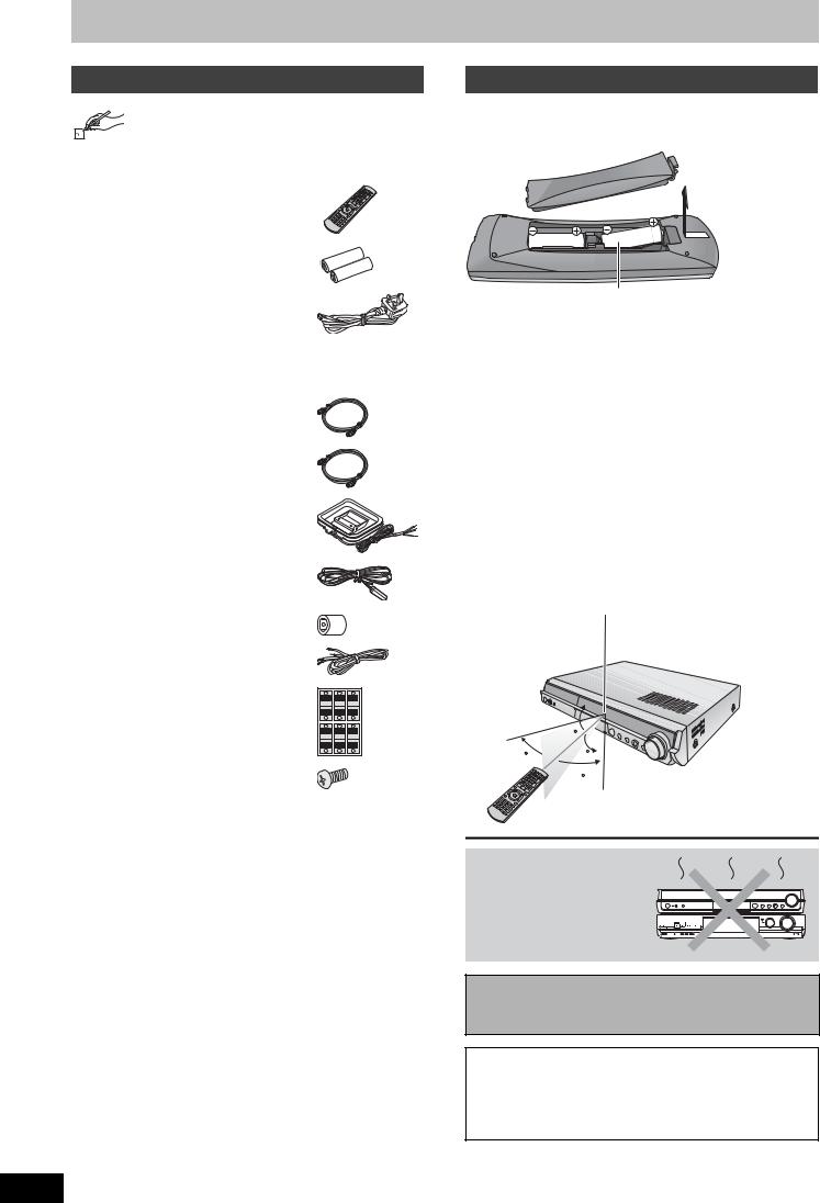
Accessories
Please check and identify the supplied accessories. Use numbers when asking for replacement parts. (Product numbers correct as of March 2006. These may be subject to change.)
∏1 Remote control
[RT30] (EUR7662Y20) [RT70] (EUR7662YA0)
∏2 Batteries
for remote control
∏1 AC mains lead
(K2CT3CA00004)
≥For use with this unit only. Do not use it with other equipment.
Also do not use cords for other equipment with this unit.
∏2 RF coaxial leads (black)
(VJA1123)
∏ 1 RF coaxial lead (grey)
(K1TWACA00001)
∏1 AM loop aerial
(N1DAAAA00002)
∏1 FM indoor aerial
(RSA0007-L)
∏1 Aerial plug adaptor
(K1YZ02000013)
∏[RT70] 2 Speaker cables
(REEX0449B-1L)
∏ 2 Sheets of speaker cable |
Lch |
Lch |
5 |
|
1 |
3 |
|
stickers |
FRONT |
SURROUND |
CENTER |
FRONT SURROUND |
CENTER |
||
|
Lch |
Lch |
|
|
1 |
3 |
5 |
|
2 |
4 |
6 |
|
Rch |
Rch |
WOOFER |
|
FRONT |
SURROUND |
SUB |
|
FRONT SURROUND |
SUB |
|
|
Rch |
Rch |
WOOFER |
|
2 |
4 |
6 |
∏ [RT70] 16 Screws
(RYQX0249)
∫ Sales and Support Information
Customer Care Centre
≥For customers within the UK: 08705 357357
≥For customers within the Republic of Ireland: 01 289 8333 ≥Visit our website for product information
≥E-mail: customer.care@panasonic.co.uk
Direct Sales at Panasonic UK
≥Order accessory and consumable items for your product with ease and confidence by phoning our Customer Care Centre Monday–Thursday 9:00am–5:30pm, Friday 9:30am–5:30pm (Excluding public holidays).
≥Or go on line through our Internet Accessory ordering application at www.panasonic.co.uk.
≥Most major credit and debit cards accepted.
≥All enquiries transactions and distribution facilities are provided directly by Panasonic UK Ltd.
≥It couldn’t be simpler!
≥Also available through our Internet is direct shopping for a wide range of finished products, take a browse on our website for further details.
Interested in purchasing an extended guarantee? Please call 0870 240 6284 or visit our website www.panasonic.co.uk/guarantee .
The remote control information
∫ Batteries
≥Insert so the poles (i and j) match those in the remote control.
R6/LR6, AA
≥Do not use rechargeable type batteries. ≥Do not mix old and new batteries.
≥Do not use different types at the same time. ≥Do not heat or expose to flame.
≥Do not take apart or short circuit.
≥Do not attempt to recharge alkaline or manganese batteries.
≥Do not use batteries if the covering has been peeled off.
Mishandling of batteries can cause electrolyte leakage which can damage items the fluid contacts and may cause a fire.
Remove the batteries if the remote control is not going to be used for a long period of time. Store in a cool, dark place.
∫ Use
Remote control signal sensor:
Receives signals within a vertical radius of approximately 20 degrees, and a horizontal radius of approximately 60 degrees.
20
30 20
30
7 m directly in front of the unit
Do not place the unit on amplifiers or equipment that may become hot.
The heat can damage the unit.
Before moving the unit, ensure the disc tray is empty. Failure to do so will risk severely damaging the disc and the unit.
≥For your safety, be sure not to connect or handle the equipment with wet hands.
≥Your attention is drawn to the fact that the recording pre-recorded tapes or discs or other published or broadcast material may infringe copyright laws.
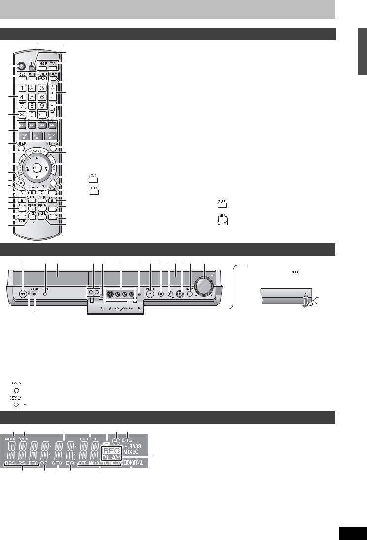
Control reference guide
Remote control
C
D
1 |
E |
|
|
2 |
|
|
F |
3 |
G |
|
|
|
H |
4 |
I |
|
|
5 |
|
6 |
J |
|
|
7 |
K |
8 |
L |
9 |
|
: |
M |
|
N |
||
; |
||
O |
||
< |
||
P |
||
= |
||
Q |
||
> |
||
VIDEO Plus+ R |
||
? |
||
@ |
S |
|
A |
T |
|
B |
U |
1 Turn the unit on |
C Remote control signal output |
|||||
2 Select the source |
D Turn on the television |
|||||
|
DVD, FM/AM, AUX/F MUSICP |
E Switches the remote control operation |
||||
3 Select channels and title numbers, etc./ |
|
between the unit and the TV. |
||||
|
Enter numbers |
|
Press [THEATER] when operating this |
|||
4 Cancel |
|
unit, or press [TV] when operating the |
||||
5 Basic operations for recording and play |
|
television. |
||||
6 Skip the specified time( 31) |
F Input select (AV1, AV2, AV3 or DV) |
|||||
7 Selection (3, 4, 2, 1)/Enter, Frame-by- |
G Channel select ( 24) |
|||||
|
frame (2;, ;1)( 31) |
H Adjust the volume |
||||
8 Show Direct Navigator/Top menu ( 30, 32, |
I Delete items ( 37) |
|||||
|
38) |
J Skip 30 seconds forward ( 31) |
||||
9 Show sub menu ( 38) |
K Show timer recording programme list ( 27) |
|||||
: Show on-screen menu ( 35) |
L Show FUNCTIONS window ( 36) |
|||||
; Select audio ( 30) |
M Return to previous screen |
|||||
< Manual tuning operation ( 53) |
N Create chapters ( 31) |
|||||
= Change recording mode ( 24) |
O Show status messages ( 33, 36) |
|||||
> Start recording ( 24) |
P Linked timer recordings with external |
|||||
? Change the sound quality ( 48) |
|
equipment ( 29) |
||||
@ |
|
|
[RT30] |
Q Direct TV recording ( 57) |
||
|
|
|
Down-mix signals to 2 channels ( 49) |
R Show VIDEO Plusr screen ( 26) |
||
|
|
|
[RT70] |
S Enhance the bass sound ( 48) |
||
|
|
|
Enhance surround sound ( 48) |
T Muting ( 49) |
||
A Enhance the sound from the center speaker |
U |
|
[RT30] |
|||
|
( 48)/ Change radio reception mode |
|
|
Adjust the subwoofer level ( 49) |
||
|
|
|
[RT70] |
|||
|
( 47) |
|
|
|||
|
|
|
Adjust the subwoofer level ( 49)/ |
|||
B Select speaker channels ( 49)/RDS ( 47) |
|
|
||||
|
|
Down-mix signals to 2 channels ( 49) |
||||
|
|
|
|
|
|
|
This unit |
|
|
|
|
1 |
4 5 |
6 7 8 9 : ; <=> ? @ |
Opening the front panel |
|
|
|
|
||
|
|
|
Press down the |
part with |
|
|
|
your finger. |
|
|
|
|
|
5 Disc tray ( 24) |
|
1 Standby/on switch (Í/I) |
|||||
6 Channel select ( 24) |
|||||
|
Press to switch the unit from on to standby mode or vice |
||||
|
7 Connector for a digital video (DV) camcorder ( 42) |
||||
|
versa. In standby mode, the unit is still consuming a small |
||||
|
8 Connector for external equipment ( 42) |
||||
|
amount of power. To save power, unplug it from the |
||||
|
9 Connector for headphones ( 56) |
||||
|
household mains socket. |
||||
|
: Open/close disc tray ( 24) |
||||
2 Standby/on indicator (Í) |
|||||
; Stop ( 24, 30) |
|||||
|
When the unit is connected to the AC mains supply, this |
||||
|
< Start play ( 30) |
||||
|
indicator lights up in standby mode and goes out when the |
||||
|
= Display ( below) |
||||
|
unit is turned on. |
||||
|
> Start recording ( 24)/Specify the time to stop recording |
||||
3 Connector for an external device ( 56) |
|||||
( 25) |
|||||
4 |
[RT30] Change the sound quality ( 48) |
||||
? Select the source |
|||||
|
|||||
DVD>FM>AM>AUX>F MUSICP>Return to DVD @ Turn up/down the volume
Accessories/The remote control information / Control reference guide
1 |
2 |
3 |
4 |
5 6 7 |
 8
8
 9
9
:
@ |
? > = |
< |
; |
1Radio broadcast display ( 47) : Channel preset memory indicator
2 D.MIX indicator ( 49)
3 Main display section
4 Linked timer recordings with external equipment indicator ( 29)
5Disc indicator
This indicator lights up when a disc that is supported by this unit is inserted.
6 Timer recording indicator ( 26)
7 DTS indicator ( 49)
8 H.BASS indicator ( 48)
9 MIX2CH indicator ( 49)
: Rec/Play indicator ( 24, 30) ; Dolby Digital indicator ( 49)
<Radio broadcast display ( 46, 47)
TUNED : Receiving radio signal/ST : Stereo/
MONO : Monaural
= Equalizer indicator ( 48)
> Sound field control indicator ( 48) ? Center Focus indicator ( 48)
@Radio broadcast display ( 47)
RDS: Receiving RDS (Radio Data System) signal PS: Programme station indicator
PTY: Programme type indicator
RQT8672
5

Disc information
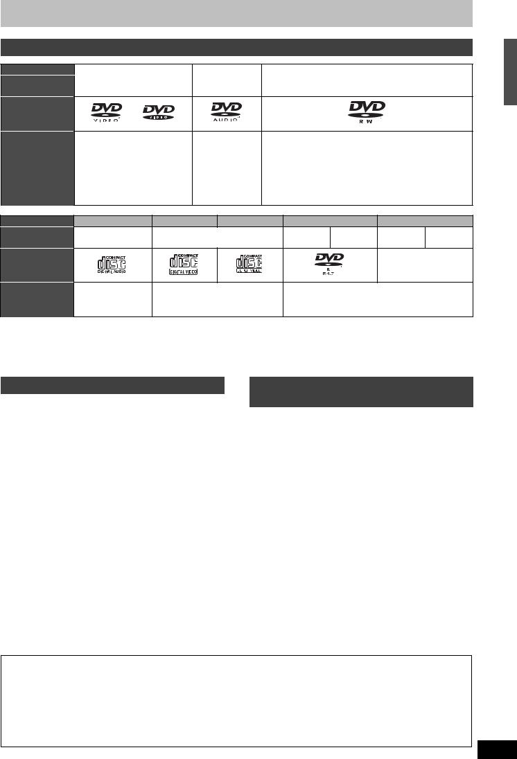
Discs you can use for recording and play
RQT8672
6
Disc type |
DVD-RAM |
DVD-R |
DVD-R DL§1 |
DVD-RW |
+R§2 |
+R DL§1 |
+RW |
||
|
|
|
|
(dual layer on |
|
|
(double layer |
|
|
|
|
|
|
single side) |
|
|
on single side) |
|
|
Indication in these |
|
[-R] |
[-R]DL] |
[-RW‹V›] |
[+R] |
[+R]DL] |
|
||
instructions |
|
Before |
Before |
Before |
Before |
Before |
|
||
|
|
[RAM] |
finalization |
finalization |
finalization |
finalization |
finalization |
[+RW] |
|
|
|
|
[DVD-V] |
[DVD-V] |
[DVD-V] |
[DVD-V] |
[DVD-V] |
|
|
|
|
|
After |
After |
After |
After |
After |
|
|
|
|
|
finalization |
finalization |
finalization |
finalization |
finalization |
|
|
Logo |
|
|
|
|
|
|
|
||
|
|
|
|
|
|
–––– |
–––– |
–––– |
|
Recording format |
|
|
|
|
|
|
|
||
VR |
DVD-Video |
DVD-Video |
DVD-Video |
+VR |
+VR |
+VR |
|||
( below) |
|||||||||
|
|
|
|
|
|
|
|||
Re-writable§3 |
|
t |
t |
|
t |
t |
|
||
|
|
||||||||
|
|
|
|
|
|
|
|
|
|
What you can do on this unit |
|
|
|
|
|
|
|||
|
Recording |
|
|
|
|
|
|
|
|
|
broadcasts that |
§4 |
t |
t |
t |
t |
t |
t |
|
|
allow one copy |
|
|
|
|
|
|
|
|
|
Recording both |
|
|
|
|
|
|
|
|
|
M 1 and M 2 of |
|
t |
t |
t |
t |
t |
t |
|
|
bilingual |
||||||||
|
|
|
|
|
|
|
|
||
|
broadcasts |
|
|
|
|
|
|
|
|
|
Recording 16:9 |
|
t |
t |
t |
t |
t |
t |
|
|
aspect picture |
||||||||
|
|
|
|
|
|
|
|
||
|
Creating playlists |
|
|
|
|
|
|
|
|
|
|
t |
t |
t |
t |
t |
t |
||
Compatibility |
|
|
|
|
|
|
|
||
|
Usable high |
|
|
|
|
|
|
|
|
|
speed recording |
Up to 5x |
Up to 16x |
Up to 4x |
Up to 6x |
Up to 16x |
Up to 2.4x |
Up to 4x§6 |
|
|
disc type§5 |
|
|
|
|
|
|
|
|
|
Play on other |
Only on DVD- |
|
§7 |
|
|
§8 |
|
|
|
players |
RAM |
|
|
|
|
|
(It is not |
|
|
|
|
|
|
|
||||
|
|
compatible |
|
|
|
|
|
possible to |
|
|
|
players. (It is |
Only on compatible players after finalizing the disc ( 45) |
finalize the |
|||||
|
|
not possible |
disc.) |
||||||
|
|
to finalize the |
|
|
|
|
|
|
|
|
|
disc.) |
|
|
|
|
|
|
|
|
|
|
|
|
|
|
: Can do, t: Cannot do |
||
≥We recommend using Panasonic discs. We also recommend using DVD-RAM discs with cartridges to protect them from scratches and dirt.
≥You may not be able to record depending on the condition of the discs and you may not be able to play due to the condition of the recording.
≥For the recording time, refer to “Recording modes and approximate recording times” on page 23.
≥You cannot record programmes that allow “One time only recording” to CPRM compatible DVD-R and DVD-RW on this unit. You can record other programmes as DVD-Video format.
§1 You cannot continue a recording from the first layer to the second layer on dualor double-layer discs. To record onto the second layer, you must first close the first layer using the “Close First Layer” item in DVD Management ( 45). You will no longer be able to record to the first layer after you do this ( 22).
When playing a title recorded on both layers, video and audio may momentarily cut out when the unit is switching layers. §2 You may not be able to use +R recorded on this unit in another Panasonic DVD recorder and vice versa. Once the disc is
finalized, however, it can be played in the other unit.
§3 The amount of the recordable disc space doesn’t increase even if the programme is deleted when you use a one time recording disc. §4 CPRM ( 65) compatible discs only.
§5 This unit can use the high-speed recording discs shown in the chart, but using them will not shorten the recording time. §6 You can play 8x recording speed discs recorded on another equipment.
§7 Play on DVD-R DL compatible equipment. §8 Play on +R DL compatible equipment.
Regarding recording format
VR (DVD Video Recording) format
This is a recording method which allows you to freely record and edit television broadcasts and so on.
≥Digital broadcasts that allow “One time only recording” can be recorded to a CPRM compatible disc. You can record to CPRM compatible DVD-RAM on this unit.
≥Play is only possible on a compatible DVD player.
DVD-Video format
This recording method is the same as commercially available DVD-Video. ≥Digital broadcasts that allow “One time only recording” cannot be recorded.
≥You can play on compatible equipment such as DVD players after finalizing the disc on this unit.
+VR (+R/+RW Video Recording) format
This is a method for recording moving pictures to +R/+RW discs. You can play back such discs recorded in this method in a similar way as contents recorded in the DVD-Video format.
≥Digital broadcast that allow “One time only recording” cannot be recorded.
≥After finalizing the disc or creating the top menu, you can play the disc on DVD players and other equipment.
Play-only discs
Disc type
Indication in these instructions
Logo
Instructions
DVD-Video |
DVD-Audio |
DVD-RW (VR format) |
[DVD-V] |
[DVD-A] |
[-RW‹VR›] |
High quality movie and music |
High fidelity music DVD-RW recorded on another DVD Recorder§1 |
|
discs |
discs |
≥You can play programmes that allow “One time only |
|
|
recording” if they have been recorded to a CPRM |
|
|
compatible disc. |
|
|
≥By formatting ( 44) the disc, you can record to it in |
|
|
DVD-Video format. |
|
|
≥It may be necessary to finalize the disc on the |
|
|
equipment used for recording. |
Disc type |
Audio CD |
Video CD |
SVCD§2 |
|
DVD-R |
|
CD |
Indication in |
[CD] |
|
[VCD] |
MP3 |
JPEG |
MP3 |
JPEG |
these instructions |
|
||||||
|
|
|
|
|
|
|
|
Logo |
|
|
|
|
|
|
|
|
|
|
|
|
|
|
–––– |
Instructions |
Music and audio |
Music and video recorded |
CD-R/RW and DVD-R§1 with MP3/Still pictures |
||||
|
recorded (including |
(including CD-R/RW§1) |
(JPEG and TIFF) |
|
|
||
|
CD-R/RW§1) |
|
|
|
|
|
|
≥The producer of the disc can control how discs are played. So you may not always be able to control play as described in these operating instructions. Read the disc’s instructions carefully.
≥Operation and sound quality of CDs that do not conform to CD-DA specifications (copy control CDs, etc.) cannot be guaranteed. §1 Close the session after recording. Play may be impossible on some discs due to the condition of the recording.
§2 Conforming to IEC62107.
Disc information
Discs that cannot be played
≥2.6 and 5.2 GB DVD-RAM, 12 cm ≥3.95 and 4.7 GB DVD-R for Authoring ≥DVD-R recorded in VR format
≥DVD-R (DVD-Video format), DVD-R DL, DVD-RW (DVDVideo format), +R, +R DL recorded on another unit and not finalized ( 65).
≥DVD-Video with a region number other than “2” or “ALL” ≥Blu-ray
≥DVD-ROM, +R (8 cm), CD-ROM, CDV, CD-G, Photo CD, CVD, SACD, MV-Disc, PD, DivX Video Disc, “Chaoji VCD” available on the market including CVD, DVCD and SVCD that do not conform to IEC62107, etc.
Types of disc for the type of connected TV
When you use the discs recorded either PAL or NTSC, refer to this table.
( : Possible to view, t: Impossible to view)
TV type |
Disc |
Yes/No |
|
|
|
Multi-system TV |
PAL |
|
|
|
|
|
NTSC |
§3 |
NTSC TV |
PAL |
t |
|
|
|
|
NTSC |
§4 |
PAL TV |
PAL |
|
|
|
|
|
NTSC |
§5 (PAL60) |
§3 If you select “NTSC” in “TV System” ( 51), the picture may be clearer.
§4 Select “NTSC” in “TV System” ( 51).
§5 If your televison is not equipped to handle PAL 525/60 signals the picture will not be shown correctly.
The manufacturer accepts no responsibility and offers no compensation for loss of recorded or edited material due to a problem with the unit or recordable media, and accepts no responsibility and offers no compensation for any subsequent damage caused by such loss.
Examples of causes of such losses are
≥A disc recorded and edited with this unit is played in a DVD Recorder or computer disc drive manufactured by another company.
≥A disc used as described above and then played again in this unit.
≥A disc recorded and edited with a DVD Recorder or computer disc drive manufactured by another company is played in this unit.
RQT8672
7
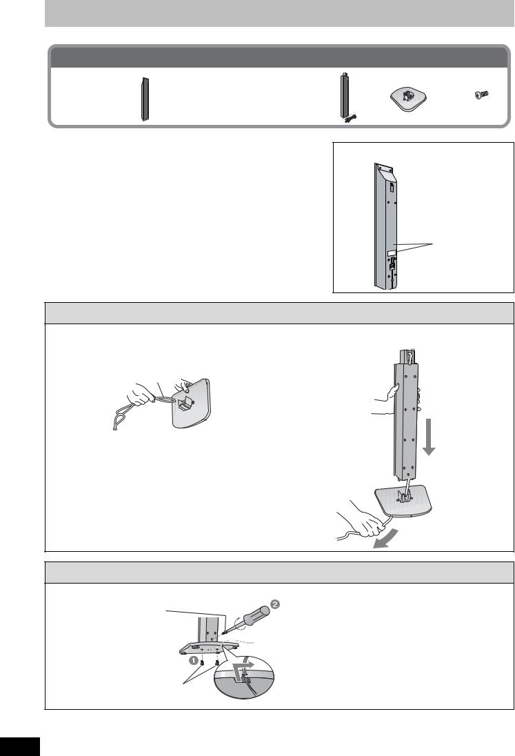
STEP 1 Front and surround speaker assembly [RT70]
Included parts to be used
2 Front and 2 Surround speakers (with cover plate)
4 Stands |
4 Bases |
16 Screws |
≥2aStands with short cable: For front speakers |
|
|
≥2aStands with long cable: For surround |
|
|
speakers |
|
|
Preparation
≥To prevent damage or scratches, lay down a soft cloth and perform assembly on it.
≥For assembly, use Phillips-head and flathead screwdrivers.
≥Make sure you have all the indicated components before starting assembly, positioning, and connection.
≥The front and surround speaker pairs as well as the stand pairs are
different.
–Check the label on the rear of the front speaker before attaching the stand ( right).
–The stand with the shorter cable is for the front speaker. ≥For optional wall mount, refer to page 17.
Front speakers
 Speaker labels
1 Attach the stand to the base.
1Thread the speaker cable through the base.
For quicker threading, loosely fold the cable in half (do not crease), pass the folded portion through the hole, and then pull the rest of the cable through the base.
Cable
Base
2Attach the stand to the base while gently pulling on the end of the speaker cable.
Stand
Base
 Cable
Cable
Pull gently.
2 Secure the stand to the base.
Screws
Tighten securely.
Stand
Base
Slide the speaker cable into the groove.
Screws
Tighten securely.
RQT8672
8
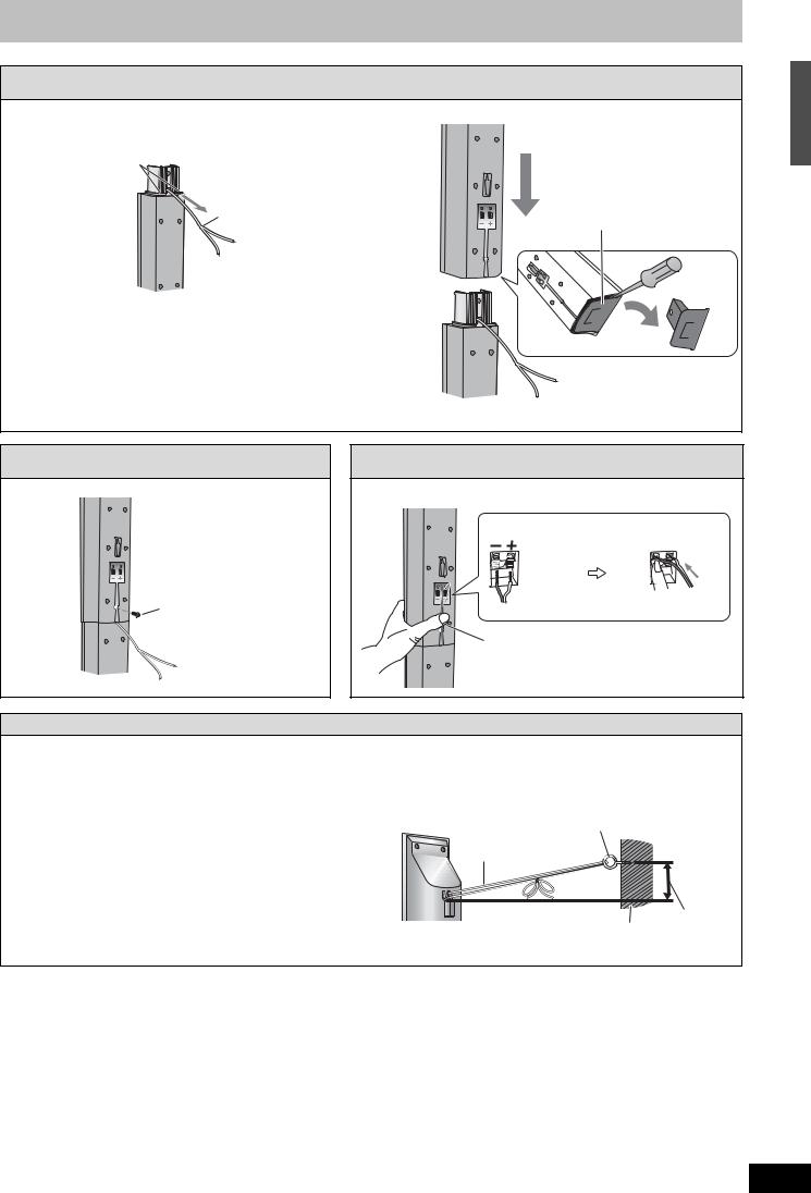
3 Attach the speaker to the stand.
1Pull out the end of the speaker cable and position it between the ridges.
Ridges
Cable
Stand
2Attach the speaker to the stand.
Speaker |
Cover plate |
Before attaching the speaker, use a flathead screwdriver carefully to remove the cover plate, and keep for wall-mount use ( 17).
Stand
4 Secure the speaker to the stand.
Speaker
|
Screw |
|
Stand |
Tighten securely. |
|
Ensure the speaker cable is |
||
|
||
|
centered in the groove. |
5 Connect the speaker cable.
Insert the wire fully. |
_: White |
`: Blue |
Push! |
Press the speaker cable into the groove. |
STEP 1 Front and surround speaker assembly [RT70]
Preventing the front and surround speakers from falling over
Preparation
Attach screw eyes (not included) to secure the speakers to the wall ( diagram right).
≥You will need to obtain the appropriate screw eyes to match the walls or pillars to which they are going to be fastened.
≥The walls or pillars to which the screw eyes are going to be fastened should be capable of supporting 20 kg. Consult a qualified housing contractor concerning the appropriate procedure when attaching to a concrete wall or a surface that may not have strong enough support. Improper attachment may result in damage to the wall or speakers.
To prevent the speaker from falling over, thread the string (not included) from the wall to the speaker as shown and tie tightly.
Rear of the speaker
Screw eye (not included)
String (not included)
Wall |
Approx. |
150 mm |
RQT8672
9
STEP 2 Positioning and connection of speakers
Included parts to be used
2 Sheets of speaker cable stickers
2 Speaker cables [RT70]
1 |
3 |
5 |
Lch |
Lch |
CENTER |
FRONT |
SURROUND |
|
FRONT |
SURROUND |
CENTER |
Lch |
Lch |
|
1 |
3 |
5 |
2 |
4 |
6 |
Rch |
Rch |
WOOFER |
FRONT |
SURROUND |
SUB |
FRONT |
SURROUND |
SUB |
Rch |
Rch |
WOOFER |
2 |
4 |
6 |
1 Place the speakers.
Preparation [RT70] |
Use only supplied speakers |
Check to make sure the screws on the front and surround |
Using other speakers can damage the unit and sound quality |
speakers are not loose. |
will be negatively affected. |
Positioning for best effect |
[Note] |
How you set up your speakers can affect the bass and the |
≥Set the speakers up on an even surface to prevent them |
sound field. |
from falling. |
Note the following points: |
Take proper precautions to prevent the speakers from falling |
≥Place the front, center, and surround speakers at |
over if you cannot set them up on an even surface. |
approximately the same distance from the seating |
≥Left and right speakers are interchangeable, but front and |
position. |
surround speakers are not. |
The angles in the diagram below are approximate. |
|
≥Place speakers on flat secure bases. |
Connect the supplied speakers and subwoofer to this unit only. |
≥Placing speakers too close to floors, walls, and corners can |
Do not attempt to connect the supplied speakers and |
result in excessive bass. Cover walls and windows with thick |
subwoofer to the external amplifier and so on. |
curtains. |
|
RT30 |
|
|
RT70 |
Do not use a front |
|
|
|
|
|
|
|
||
|
|
|
|
speaker as a surround |
||
|
|
|
|
speaker or vice versa. |
||
Front |
Surround |
Center |
Subwoofer |
|
Center |
Subwoofer |
speaker |
speaker |
speaker |
Front |
Surround |
||
(L, R) |
(L, R) |
|
speaker |
speaker |
speaker |
|
|
|
|
(L, R) |
(L, R) |
|
|
|
This unit |
|
|
This unit |
|
|
This unit |
|
|
Center speaker |
Caution |
|
|
|
|
|
≥Vibration caused by the center speaker |
≥This unit and supplied speakers are |
|
|
|
||
[Note] |
can disrupt the picture if it is placed |
only to be used as indicated in this |
||
≥Keep your speakers at least 10 mm |
directly on the television. |
setup. Failure to do so may lead to |
||
away from this unit for proper |
Put the center speaker on a rack or |
damage to the amplifier and/or the |
||
ventilation. |
shelf. |
speakers, and may result in the risk |
||
≥To allow for proper ventilation and to |
≥To prevent the speaker from falling, do |
of fire. Consult a qualified service |
||
maintain good airflow around this unit, |
not place the speaker directly on top of |
person if damage has occurred or if |
||
position it with enough space on all |
the television. |
you experience a sudden change in |
||
sides. |
|
performance. |
||
≥Do not block the ventilation holes of |
|
≥ Do not attempt to attach these |
||
this unit. |
|
speakers to walls using methods |
||
≥Do not set anything on top of this unit. |
|
other than those described in this |
||
Subwoofer |
|
manual. |
||
|
|
|||
Place to the right or left of the television |
|
|
||
on the floor so that it won’t cause |
|
|
||
vibration. |
|
|
||
RQT8672 Leave about 30 cm from the television. |
|
|
||
10
2 Connect the speaker cables.
|
|
e.g. [RT70] Center speaker |
1 |
Attach the speaker cable stickers (included) to speaker cables to make |
Speaker cable sticker |
|
connection easier. |
|
2 |
Insert the speaker cables into the terminals in accordance with the stickers you just attached |
|
|
and the diagram below. |
|
[RT30] All speaker cables are fixed to the back of the speakers from the time of shipment. You only need to connect the speaker cables to the terminal on this unit.
The illustration shows SC-RT70, but this connection method is also used for SC-RT30.
[RT70] The front and surround speaker cables were connected to the back of the speakers in step 1 ( 9). Connect the supplied speaker cables to the center speaker and subwoofer, and then connect all the speaker cables to this unit.
Front speaker (R)
Subwoofer
6
Surround speaker (R)
 4
4
Back of this unit
|
|
|
|
|
|
|
|
|
Insert the wire fully. |
Front speaker (L) |
|
|
|
|
|
|
|
|
|
|||
|
|
|
|
|
|
|
|
|
|
|
|
|
|
|
|
|
|
|
|
|||
|
|
|
|
|
|
|
|
|
`: Blue _: White |
|
|
|
|
|
|
|
|
|
|
|
|
|
|
|
|
|
|
|
5 |
|
|
|
Center speaker |
|
|
|
|
|
|
|
|
|
|
|
|
|
|
|
|
|
|
|
|
|
|
|
|
|
|
|
|
|
|
|
|
|
||
|
|
|
|
|
|
|
|
|
|
|
|
|
|
|
|
|
|
|
|
|
||
2 |
|
|
|
1 |
|
|
|
|
|
|
|
|
|
|
|
|||||||
|
|
|
|
|
|
|
|
|
|
|
|
|
|
|
||||||||
|
|
|
|
|
|
|
|
|
|
Insert the wire fully. |
|
|
Surround speaker (L) |
|
|
|||||||
|
|
|
|
|
|
|
|
|
|
|
|
|
|
|||||||||
|
|
|
|
|
|
|
|
|
|
_: White |
|
|
|
|
|
|
|
|
|
|
|
|
|
|
|
|
|
|
|
|
|
|
`: Blue |
|
|
|
|
|
|
|
|
|
|
|
|
|
|
|
|
|
|
|
|
|
|
SURROUND |
SURROUND |
|
|
|
|
|
|
|
|
|
|
|
|
|
|
|
|
|
|
|
|
|
Lch |
Lch |
|
|
|
|
|
|
|
|
|
|
|
|
|
|
|
|
|
|
|
|
|
|
|
|
|
|
|
|
|
|
|
|
|
|
|
|
|
|
|
|
|
|
|
|
|
|
|
|
|
|
|
|
|
|
|
|
|
|
|
|
|
|
|
|
|
|
|
Caution |
|
|
|
|
|
|
|
|
|
|||
|
|
|
|
|
|
|
|
|
|
≥Be careful not to cross |
|
|
|
|
|
|
|
|
|
|||
|
|
|
|
|
|
|
|
|
|
|
|
|
|
|
|
|
|
|
||||
|
|
|
|
|
|
|
|
|
|
(short-circuit) or reverse the |
|
|
|
|
|
|
|
|
|
|||
|
|
|
|
|
|
Click! |
polarity of the speaker wires |
|
|
|
|
|
|
|
|
|
||||||
|
|
|
|
|
|
as doing so may damage the |
|
|
|
|
|
|
|
|
|
|||||||
|
|
|
|
|
|
|
|
|
|
Blue |
|
|
|
|
White |
|||||||
|
|
|
|
|
|
|
|
|
|
speakers. |
|
|
|
|||||||||
|
|
|
|
|
|
|
|
|
|
|
|
|||||||||||
|
|
|
|
|
|
|
|
|
|
|
|
|
|
|
|
|
|
|
||||
STEP 2 Positioning and connection of speakers
Caution |
|
|
|
≥Do not stand on |
[RT70] Front and |
||
surround |
|||
the base. |
speakers |
||
Be cautious when |
|
|
|
children are near. |
|
|
|
|
|
|
|
|
|
|
|
≥Do not touch the netted area of the speakers.
e.g. [RT30] Surround speakers
Notes on speaker use
≥You can damage your speakers and shorten their useful life if you play sound at high levels over extended periods.
≥Reduce the volume in the following
cases to avoid damage: –When playing distorted sound.
–When the speakers are reverberating due to a record player, noise from FM broadcasts, or continuous signals from an oscillator, test disc, or electronic instrument.
–When adjusting the sound quality. –When turning the unit on or off.
If irregular colouring occurs on your television
The front and center speakers are designed to be used close to a television, but the picture may be affected with some televisions and setup combinations.
If this occurs, turn the television off for about 30 minutes.
The television’s demagnetizing function should correct the problem. If it persists, move the speakers further away from the television.
RQT8672
11
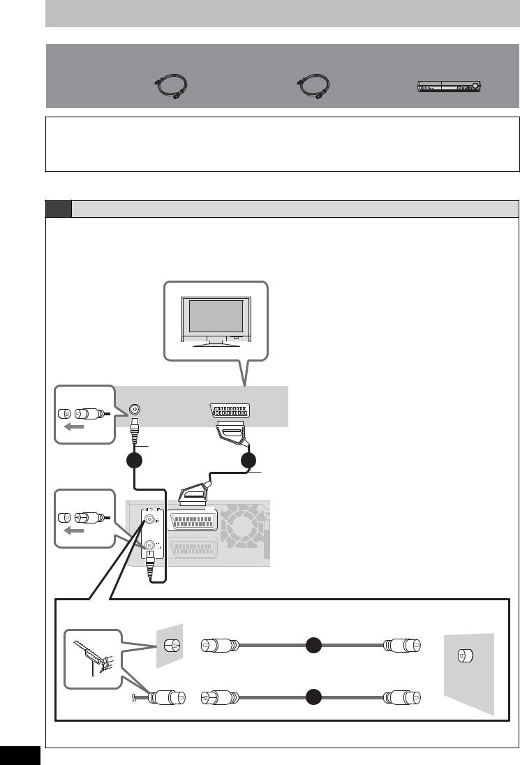
STEP 3 Video connections
Included parts to be used
2 RF coaxial leads |
1 RF coaxial lead |
This unit |
(black) |
(grey) |
|
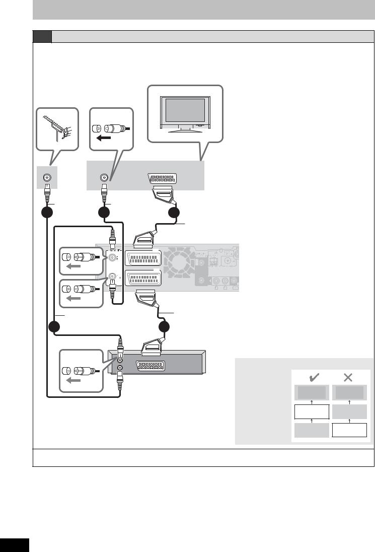
Use the supplied RF coaxial leads
To prevent interference patterns from appearing on your TV, use only the supplied RF coaxial leads when you connect this unit to your TV and aerial outlet or aerial lead, as shown in connection types A–C.
≥Keep the RF coaxial leads as far away as possible from other leads.
≥Do not roll up the RF coaxial leads.
≥Before connection, turn off the mains for all connected equipment and read the appropriate operating instructions.
≥Choose from one of the connection types A–C that suits your requirement.
A Connecting to a television only
Using a fully wired 21-pin Scart lead
≥You can use a variety of Q Link functions by connecting the unit to a Q Link compatible television ( 57).
≥You can enjoy high-quality viewing by connecting the unit to an RGB compatible television.
[Required[setting]
“AV1 Output” in the Setup menu ( 51)
Television’s rear panel
VHF/UHF |
AV |
RF IN |
RF coaxial lead
2 |
(included, black) |
(TV) |
AV1 |
(EXT) |
AV2 |
3
Fully wired 21-pin Scart lead§ (For Q Link functions)
(not included)
§This connection will enable you to play audio
from your television through3 your home
theater system. Refer to “Enjoying TV broadcast with this unit’s
 speakers” ( 56).
Back of this unit
Use one of the RF coaxial lead (black or grey) to connect this unit’s RF IN terminal to your aerial socket or aerial lead.
To the aerial |
RF coaxial lead (included, grey) |
This unit |
|
1
or |
RF |
|
IN |
||
|
RF coaxial lead (included, black)
1
Connecting a terminal other than the 21-pin Scart terminal ( 15).
RQT8672
12
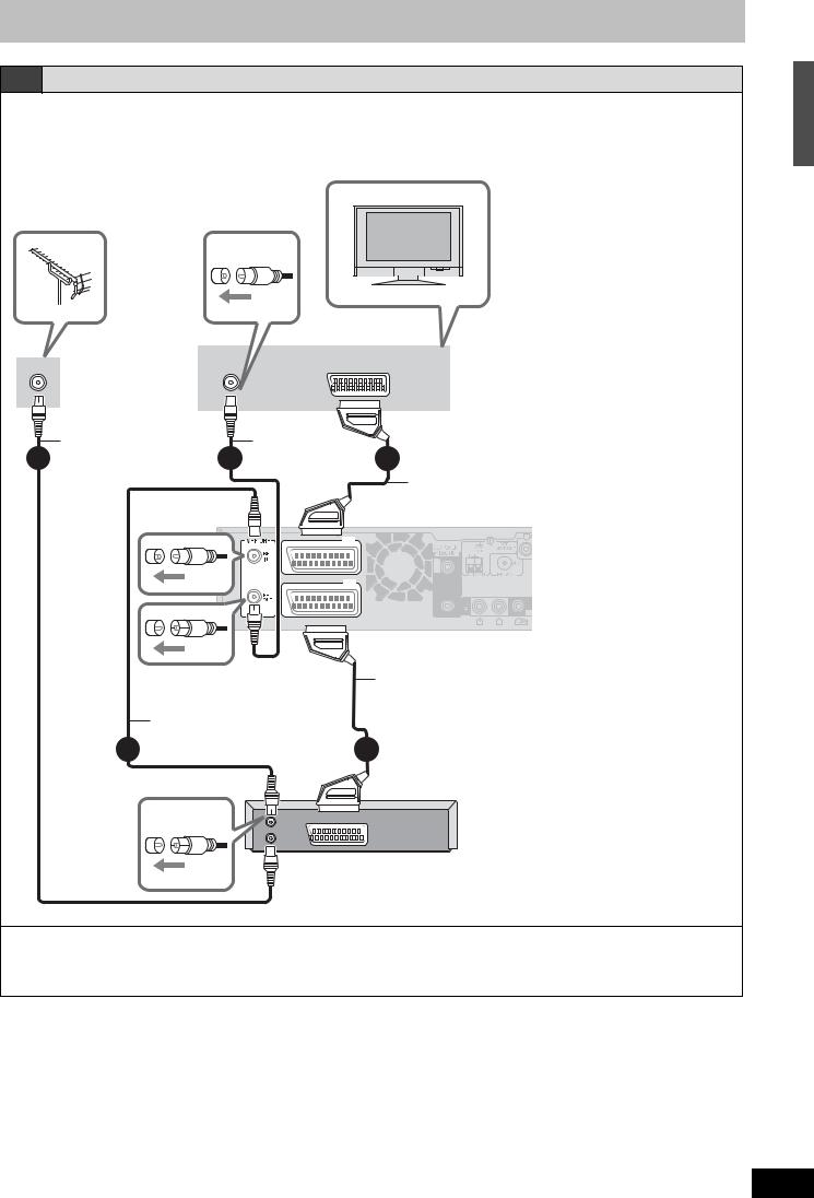
B Connecting to a television and Satellite/Digital terrestrial receiver
Using a fully wired 21-pin Scart lead
≥You can use a variety of Q Link functions by connecting the unit to a Q Link compatible television ( 57).
≥You can enjoy high-quality viewing by connecting the unit to an RGB compatible television.
[Required[setting]
“AV1 Output” and “AV2 Input” in the Setup menu ( 51)
Television’s rear panel
VHF/UHF
RF IN
To the aerial
|
RF coaxial lead |
|
1 |
(included, grey) |
3 |
|
RF coaxial lead
(included, black)
2
AV
RF coaxial lead |
|
(included, black) |
4 |
|
Fully wired 21-pin Scart lead§ (For Q Link functions)
(not included)
(TV) |
AV1 |
(EXT) |
AV2 |
|
§This connection will enable you to play audio3
 from
from your television through your home theater system.
 Refer to
 “Enjoying
 TV
TV broadcast with
 this unit’s
 speakers” ( 56).
Back of this unit
Fully wired 21-pin Scart lead (For External Link function)
(not included)
5
RF |
AV OUT |
OUT |
|
RF |
|
IN |
|
Satellite/Digital terrestrial receiver’s rear panel
To view satellite/digital terrestrial programmes
Press [INPUT] to select the input channel “AV2” or put this unit in standby mode.
To record satellite/digital terrestrial programmes
Refer to “Recording from a satellite/digital terrestrial receiver” ( 29).
Connecting a terminal other than the 21-pin Scart terminal ( 15).
STEP 3 Video connections
RQT8672
13
STEP 3 Video connections
C Connecting to a television and VCR
Using a fully wired 21-pin Scart lead
≥You can use a variety of Q Link functions by connecting the unit to a Q Link compatible television ( 57).
≥You can enjoy high-quality viewing by connecting the unit to an RGB compatible television.
[Required[setting]
“AV1 Output” and “AV2 Input” in the Setup menu ( 51)
Television’s rear panel
VHF/UHF |
AV |
RF IN |
To the aerial
RF coaxial lead |
RF coaxial lead |
|
1 (included, grey) 3 |
(included, black) |
4 |
(TV) |
AV1 |
(EXT) |
AV2 |
Fully wired 21-pin Scart lead§ (For Q Link functions)
(not included)
§This connection will enable you to play audio from your television3 through your home theater system. Refer to “Enjoying TV broadcast with
 this unit’s speakers” ( 56).
RF coaxial lead
2 (included, black)
Back of this unit
Fully wired 21-pin Scart lead (For External Link function)
(not included)
5
RF |
AV OUT |
OUT |
|
RF |
|
IN |
|
VCR’s rear panel
Connect the unit directly to the television
Video signals fed |
|
|
|
through video |
|
|
|
cassette recorders |
Television |
Television |
|
will be affected by |
|||
copyright |
|
|
|
protection systems |
This unit |
VCR |
|
and the picture will |
|||
|
|
||
not be shown |
VCR |
This unit |
|
correctly on the |
|||
television. |
|
|
To copy from a VCR
Refer to “Copying from a video cassette recorder” ( 42).
Connecting a terminal other than the 21-pin Scart terminal ( 15).
RQT8672
14

In the patterns “A”–”C” ( 12–14), you can also connect this unit and TV with the VIDEO OUT, S VIDEO OUT, and COMPONENT VIDEO OUT terminals instead of connecting with a fully wired 21-pin Scart cable.
Other connections
Connecting to a television with VIDEO terminal
Television’s rear panel
VIDEO |
S VIDEO |
AUDIO |
|
IN |
IN |
OUT |
|
|
|
R |
L |
Video cable |
Audio cable§ |
(not included) |
(not included) |
Back of this unit
§This audio connection will enable you to play audio from your television through your home theater system. Refer to “Enjoying TV broadcast with this unit’s speakers” ( 56).
Connecting to a television with
S VIDEO terminal
The S VIDEO OUT terminal achieves a more vivid picture than the VIDEO OUT terminal. (Actual results depend on the television.)
Television’s rear panel
VIDEO |
S VIDEO |
AUDIO |
|
IN |
IN |
OUT |
|
|
|
R |
L |
S Video cable |
|
|
|
|
|
|
|
Audio cable§ |
||
|
|
|
|
|
|
|
||||
(not included) |
|
|
|
|
|
(not included) |
||||
|
|
|
|
|
|
|
|
|
|
|
|
|
|
|
|
|
|
|
|
|
|
|
|
|
|
|
|
|
|
|
|
|
|
|
|
|
|
|
|
|
|
|
|
|
|
|
|
|
|
|
|
|
|
|
|
|
|
|
|
|
|
|
|
|
|
Back of this unit
§This audio connection will enable you to play audio from your television through your home theater system. Refer to “Enjoying TV broadcast with this unit’s speakers” ( 56).
STEP 3 Video connections
Connecting to a television with COMPONENT VIDEO terminal
Television’s rear panel
COMPONENT |
VIDEO |
S VIDEO |
AUDIO |
|
VIDEO IN |
|
|||
IN |
IN |
OUT |
|
|
|
|
|||
|
|
|
R |
L |
Audio cable§
(not included)
Video cable
(not included)
Back of this unit
§This audio connection will enable you to play audio from your television through your home theater system. Refer to “Enjoying TV broadcast with this unit’s speakers” ( 56).
COMPONENT VIDEO terminals can be used for either interlace or progressive output ( 65) and provide a purer picture than the S VIDEO OUT terminal.
≥Connect to terminals of the same colour.
If you have a regular television (CRT: cathode ray tube)
Use component output with progressive “Off” (Factory setting 51), even if it is progressive compatible, because progressive output can cause some flickering. This is the same for multi system televisions using PAL mode.
CRT
COMPONENT
VIDEO OUT
|
Progressive |
COMPONENT |
|
This unit |
output |
||
VIDEO IN |
RQT8672
15
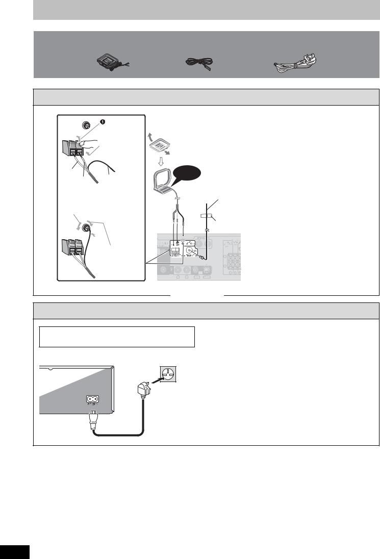
STEP 4 Radio and AC mains lead connections
Included parts to be used
AM loop aerial |
FM indoor |
AC mains lead |
aerial
1 Connect the aerials.
Push up.
 Insert the aerial cables fully.
White
Red Black
 Loosen the terminal with a Phillips-head screwdriver.
4
5 Tighten the terminal screw again.
AM loop aerial
Stand the aerial up on its base. Place the aerial where reception is best.
Keep loose aerial cable away from other wires and cables.
Click!
FM indoor aerial
Affix this end of the aerial where reception is best. Use FM outdoor aerial if radio reception is poor ( 47).
Adhesive tape
Back of this unit
2 Connect the AC mains lead.
BE SURE TO READ THE CAUTION FOR THE AC MAINS LEAD ON PAGE 2 BEFORE CONNECTION.
To household mains socket
(AC 230 to 240 V, 50 Hz)
AC mains lead (included)
Back of this unit
 AC IN terminal
Conserving power
This unit consumes a small amount of power, even when it is turned off. To save power when the unit is not to be used for a long time, unplug it from the household mains socket.
Set the unit to standby mode and remove the AC mains lead after “BYE” disappears from the unit’s display.
≥You will need to reset some memory items in the unit after plugging.
[Note]
The included AC mains lead is for use with this unit only. Do not use it with other equipment. Also, do not use cords for other equipment with this unit.
RQT8672
16
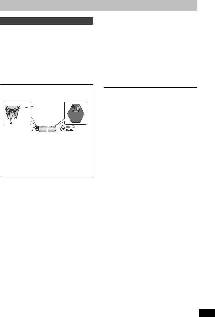
Speaker installation options
Attaching to a wall
You can attach all of the speakers (except subwoofer) to a wall.
≥The wall or pillar on which the speakers are to be attached should be capable of supporting 10 kg per screw. Consult a qualified building contractor when attaching the speakers to a wall. Improper attachment may result in damage to the wall and speakers.
[RT70]
When mounting the front and surround speakers to a wall, we recommend using a string (not included) to prevent it from falling ( 9).
[RT70] Preparation for the front and surround speakers
1 Removing the speaker cable from the stand.
 Release the cable from the groove.
Stand
2Attach the cover plate to the speaker.
The speakers are shipped with the cover plate attached.
Cover plate ( 9)
Screw
Tighten securely.
3 Connect the speaker cable. ( 9)
1 Drive a screw (not included) into the wall.
‡ 7.0 to 9.4 mm
‡ 4.0 mm
5.0 to 7.0 mm Wall or pillar
2Fit the speaker securely onto the screw(s) with the hole(s).
e.g. Front and surround |
Center speaker |
||
speakers [RT70] |
|
|
|
|
|
|
|
|
|
|
|
106 mm
200 mm
340 mm
Front speaker [RT30] |
Surround speaker [RT30] |
|
|
|
|
|
|
|
options |
|
e.g. |
|
|
installation |
|
|
|
|
||
In this position, |
|
Move the speaker |
|
|
the speaker will |
|
so that the screw |
|
|
likely fall if moved |
|
is in this position. |
|
|
to the left or right. |
|
|
connections/Speaker |
|
[RT70] Reattaching the speaker cable to the stand |
||||
|
||||
1 Remove the eight screws |
|
Screws |
|
|
from the stand, and remove |
|
|||
|
|
|||
the speaker net. |
|
|
|
|
2 Position the cable. |
|
|
|
|
Press the cable |
|
|
||
into the groove. |
|
lead |
||
Approx. |
Cable |
|
||
150 mm |
|
|
mains |
|
|
|
|
||
3 Attach the speaker net with the screws. |
AC |
|||
|
|
|
||
Fitting speaker stands (not included) |
and |
|||
(Except [RT70] Front and surround speakers) |
Radio |
|||
|
||||
Ensure the stands meet these conditions before purchasing |
|
|||
them. |
|
|
4 |
|
Note the diameter and length of the screws and the distance |
||||
STEP |
||||
≥The stands must be able to support over 10 kg. |
||||
between screws as shown in the diagram. |
|
|
||
≥The stands must be stable even if the speakers are in a high position.
e.g. Center speaker [RT30]
Attach the stands to these metal screw holes.
‡ 5 mm, pitch 
 0.8 mm

 Plate thickness
plus 7 mm to 10 |
60 mm |
|
|
mm |
|
|
Speaker stand |
|
(not included) |
RQT8672
17
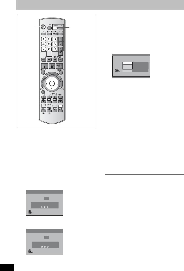
TV Tuning (Auto Setup)
Í |
THEATER |
|
Numbered  buttons
¢ 


 3,4,2,1
ENTER
 RETURN


 VIDEO Plus+


 VIDEO Plusi
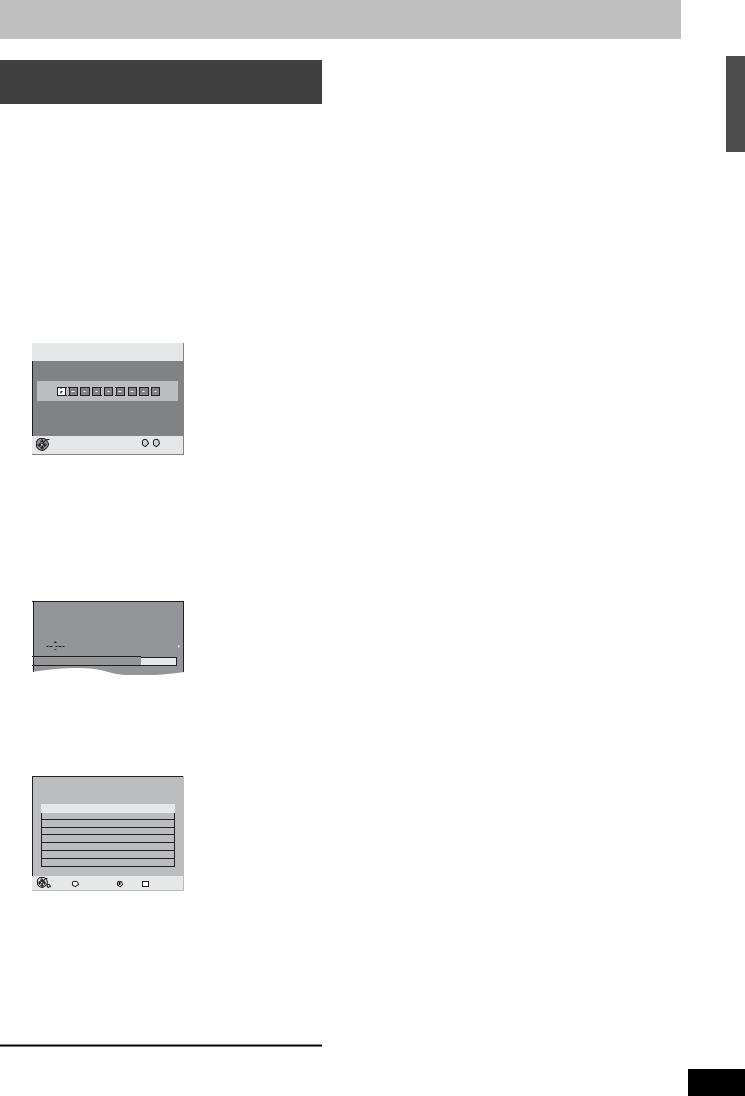
≥After pressing [Í] to turn the unit on for the first time, the unit starts necessary setup.
If the setup screen does not appear, press [DVD], and turn off this unit and on again.
1 Turn on the mains for the television (and connected equipment) and select the AV input for this unit.
2 Press [THEATER] to switch the remote control to operate this unit.
3 Press [Í] to turn the unit on.
≥If the TV is Q Link compatible, it will start to download TV tuning information to this unit.
Download from TV
Pos 4
Download in progress, Please wait.
RETURN: to cancel
RETURN
≥If the TV is not Q Link compatible, Auto Setup will start to tune in all available TV stations. This may take about 5 minutes.
Auto-Setup
Ch 1
Auto-Setup in progress, Please wait.
RETURN: to cancel
RETURN
RQT8672
4 When setup has completed, the confirmation
screen appears.
Press [ENTER].
5 The owner ID settings screen appears.
Press [1] and press the numbered buttons to enter your choice of a 4- digit PIN number.
Owner ID
PIN number  ¢¢¢¢
¢¢¢¢
Name
House No.
Postcode
RETURN
 RETURN : leave
Make a note of the PIN number (don’t forget), as it is not possible to return to the factory preset.
6 Press [ENTER] to store the PIN number.
7 Press [2, 1] to select “Yes” and
press [ENTER].
The cursor moves to “Name”.
8 Press [1].
9 Press [3, 4] to select a letter and then press [1] to move to next character.
Repeat this to enter the name.
10 Press [ENTER] to store the name.
11 Press [4] and [1], and then repeat steps 9, 10 to enter and store “House No.” and “Postcode”.
12 Press [RETURN].
The Owner ID settings screen disappears.
To abort Auto Setup
Press [RETURN].
∫If the clock setting menu appears
Set the clock manually ( 55).
∫To confirm that stations have been tuned correctly ( 53)
∫Resetting channel setting ( 54)
∫To enter the satellite station’s name ( 53)
The name of the satellite station may not be set automatically.
(“____” will appear under “Name” in the programme list.) In this case, enter the name manually.
[Note]
If this unit is connected to a digital TV (Freeview), only the analogue station’s tuning information will be downloaded.
18
Timer recording from satellite receiver with VIDEO Plus+ system
This unit is not designed to control (turn on or change channels on) your satellite receiver. However, you can use VIDEO Plus+ Recording by making the satellite receiver’s PlusCode numbers available for recognition on this unit. Take the following steps to make all satellite stations available for recognition on this unit.
Through these steps, you can make timer recording from satellite stations with VIDEO Plus+ system constantly available as the unit keeps the setting in memory.
Preparation
≥Turn on the Satellite receiver(s).
≥Select a correct station on the Satellite receiver(s).
1 Press [VIDEO Plusr].
VIDEO Plus+ Remain 1:58 SP
Record |
12:53:00 15/ 7 TUE |
Input PlusCode Number 0-9, and press ENTER.
ENTER
0 -- 9 Number
 RETURN
2 Press the numbered buttons to enter the VIDEO number for a satellite station (e.g. Sky One).
≥To correct the number
Press [2] to correct any mistakes.
3 Press [ENTER].
“____” will appear in the “Name” column.
Timer |
|
Remain |
DVD |
1:58 SP |
||
Recording |
|
|
12:54:00 |
15/ 7 TUE |
||
|
Name Date |
Start |
Stop |
Mode |
|
|
|
|
15/ 7 TUE |
19:00 |
20:00 |
SP |
|


 Programme Name
4 Press [3, 4] to select the channel or
AV input that is to be used for recording from the satellite station.
5 Press [ENTER].
Timer |
Remain |
1:58 SP |
|||
Recording |
12:53:00 |
15/ 7 TUE |
|||
|
No. Name Date |
Start Stop |
Mode |
Drive |
|
|
space |
|
|||
F01 AV2 15/ 7 TUE 19:00 20:00 SP |
OK |
||||||
|
|
|
New Timer Programme |
|
|||
|
|
|
|
|
|
|
|
|
|
|
|
|
|
|
|
|
|
|
|
|
|
|
|
|
|
|
|
|
|
|
|
|
|
|
|
|
|
|
|
|
|
|
|
|
|
|
|
|
|
|
|
|
|
|
|
|
|
|
|
|
|
|
|
ENTER |
|
|
|
RETURN |
S SUB MENU |
Delete |
A Timer Off |
6 Press [3, 4] to select the programme that you have just set and press [¢] to delete it from the timer recording list.
It is no longer needed.
Repeat the steps above until you have set dummy timer recordings for each of the satellite stations that you will make VIDEO Plus+ recordings from.
To exit the screen
Press [RETURN].
TV Tuning (Auto Setup)
RQT8672
19
Set up to match your television and remote control
|
THEATER |
Í |
TV |
|
|
|
TV operation |
DVD |
buttons |
Numbered |
|
buttons |
|
 FUNCTIONS
3,4,2,1 


ENTER
 RETURN


 VIDEO Plus+
Preparation
∫Turn on the mains for the television (and connected equipment) and select the AV input for this unit.
∫Press [THEATER] to switch the remote control to operate this unit.
∫Press [Í] to turn the unit on.
∫Press [DVD] to select the DVD drive.
Selecting television type and aspect
Choose the setting to suit your television and preference.
1 While stopped
Press [FUNCTIONS].
2 Press [3, 4] to select “To Others” and press [ENTER].
FUNCTIONS |
No Disc |
 No Disc
VIDEO Plus+ Record
Recording
Setup
To Others
 ENTER
ENTER
 RETURN
3 Press [3, 4] to select “Setup” and press [ENTER].
Setup |
Manual |
|
|
|
|
|
Auto-Setup Restart |
|
Tuning |
Download from TV |
|
|
|
|
Disc |
|
|
Picture |
|
|
Sound |
|
|
Display |
|
|
Connection |
TAB |
SELECT |
Others |
|
RETURN |
|
|
|
4 Press [3, 4] to select “Connection” and press [1].
5 Press [3, 4] to select “TV Aspect”
RQT8672
and press [ENTER].
20
6 Press [3, 4] to select the TV aspect and press [ENTER].
Setup |
|
TV Aspect |
|
|
16:9 WIDE TV |
||
|
|
16:9 |
|
|
|
|
|
Tuning |
4:3 TV |
||
|
|
|
|
Disc |
|
4:3 |
|
|
|
|
|
Picture |
|
Letterbox |
|
|
|
|
|
Sound |
|
Display |
SELECT |
Connection |
|
Others |
ENTER |
RETURN |
≥16:9: 16:9 widescreen television
≥4:3: 4:3 standard aspect television
[RAM] Even if it records and plays, the aspect does not change.
[DVD-V] Video recorded for a widescreen is played as Pan & Scan (unless prohibited by the producer of the disc) ( 65).
≥Letterbox: 4:3 standard aspect television Widescreen picture is shown in the letterbox style ( 65).
To enjoy progressive video
You can enjoy progressive video by connecting this unit’s COMPONENT VIDEO OUT terminals to an LCD/plasma television or LCD projector compatible with progressive scan ( 65).
1 While stopped
Press [FUNCTIONS].
2 Press [3, 4] to select “To Others” and press [ENTER].
3 Press [3, 4] to select “Setup” and press [ENTER].
4 Press [3, 4] to select “Connection” and press [1].
5 Press [3, 4] to select “AV1 Output” and press [ENTER].
6 Press [3, 4] to select “Video (with component)” or “S Video (with component)” and press [ENTER].
Set according to the signal and terminal of the connected TV.
7 Press [3, 4] to select “Progressive” and press [ENTER].
8 Press [3, 4] to select “On” and press
[ENTER].
Output becomes progressive.
[Note]
≥When connected to a regular television (CRT: Cathode ray tube) or a multi system television using PAL mode, even if it is progressive compatible, progressive output can cause some flickering. Turn off “Progressive” if this occurs.
≥Picture will not be displayed correctly if connected to an incompatible television.
≥There is no output from the COMPONENT VIDEO OUT terminals if “AV1 Output” in the Setup menu is set to “RGB 1 (without component)” or “RGB 2 (without component)” ( 51).
To return to the previous screen
Press [RETURN].
To exit the screen
Press [RETURN] several times.
Television operation
You can operate the TV through the unit’s remote control.
Point the remote control at the television
While pressing [Í TV], enter the code with the numbered buttons.
e.g. 01: |
[0] [1] |
|
|
Manufacturer and Code No. |
|
|
|
|
|
|
|
Brand |
Code |
Brand |
Code |
Panasonic |
01/02/03/ |
NOKIA |
25/26/27 |
|
04/45 |
|
|
|
|
|
|
AIWA |
35 |
NORDMENDE |
10 |
AKAI |
27/30 |
ORION |
37 |
|
|
|
|
BLAUPUNKT |
09 |
PHILIPS |
05/06 |
BRANDT |
10/15 |
PHONOLA |
31/33 |
|
|
|
|
BUSH |
05/06 |
PIONEER |
38 |
CURTIS |
31 |
PYE |
05/06 |
|
|
|
|
DESMET |
05/31/33 |
RADIOLA |
05/06 |
DUAL |
05/06 |
SABA |
10 |
|
|
|
|
ELEMIS |
31 |
SALORA |
26 |
FERGUSON |
10 |
SAMSUNG |
31/32/43 |
|
|
|
|
GOLDSTAR/LG |
31 |
SANSUI |
05/31/33 |
GOODMANS |
05/06/31 |
SANYO |
21 |
|
|
|
|
GRUNDIG |
09 |
SBR |
06 |
HITACHI |
22/23/31/ |
SCHNEIDER |
05/06/29/ |
|
40/41/42 |
|
30/31 |
|
|
|
|
INNO HIT |
34 |
SELECO |
06/25 |
IRRADIO |
30 |
SHARP |
18 |
|
|
|
|
ITT |
25 |
SIEMENS |
09 |
JVC |
17/39 |
SINUDYNE |
05/06/33 |
|
|
|
|
LOEWE |
07/46 |
SONY |
08 |
METZ |
28/31 |
TELEFUNKEN |
10/11/12/ |
|
|
|
13/14 |
|
|
|
|
MITSUBISHI |
06/19/20 |
THOMSON |
10/15/44 |
MIVAR |
24 |
TOSHIBA |
16 |
|
|
|
|
NEC |
36 |
WHITE |
05/06 |
|
|
WESTINGHOUSE |
|
Test by turning on the television ([Í TV]) and changing channels ([W X CH]) after pressing [TV].
Repeat the procedure until you find the code that allows correct operation.
This setting is retained.
Operating the television
1Press [TV] to switch the remote control to operate the television.
2Operate the television by pressing [Í TV] (turn on/off the television), [INPUT] (input select), [W X CH] (channel select) or [_ j VOLUME]
(adjust the volume).
≥When operating this unit, press [THEATER] to switch the remote control.
≥If your television brand is not listed or if the code listed for your television does not allow control of your television, this remote control is not compatible with your television.
When other Panasonic products respond to this remote control
When other Panasonic products placed nearby affect this |
|
||||||
unit’s remote control, change the remote control code on this |
|
||||||
unit and the remote control (the two must match). |
control |
||||||
Use “DVD 1”, the factory set code, under normal |
|||||||
|
|||||||
circumstances. |
|
|
|
|
|||
To change the code on this unit |
remote |
||||||
1 |
While stopped |
||||||
|
|||||||
|
Press [FUNCTIONS]. |
and |
|||||
2 |
Press [3, 4] to select “To Others” |
||||||
television |
|||||||
|
and press [ENTER]. |
||||||
|
|
||||||
3 Press [3, 4] to select “Setup” and |
your |
||||||
|
press [ENTER]. |
||||||
4 |
press [1]. |
4] to select “Others” and |
matchto |
||||
Press [3, |
|
||||||
5 |
Press [3, 4] to select “Remote |
up |
|||||
Set |
|||||||
|
Control” and press [ENTER]. |
||||||
|
|
||||||
6 Press [3, 4] to select the code (“DVD |
|
||||||
|
1”, “DVD 2” or “DVD 3”) and press |
|
|||||
|
[ENTER]. |
|
|
|
|||
|
|
|
|
|
|
|
|
|
|
Setup |
|
Remote Control |
|
|
|
|
|
|
|
|
|
||
|
|
|
Press “±” and “ENTER” together |
|
|
||
|
|
Tuning |
for more than 2 seconds on the remote |
|
|
||
|
|
Disc |
control. |
|
|
||
|
|
|
|
|
|
|
|
|
|
Picture |
|
|
|
|
|
|
|
|
|
|
|||
To change the code on the remote control |
|
||||||
7 While pressing [ENTER], press and hold the numbered button ([1], [2] or [3]) for more than 2 seconds.
8 Press [ENTER].
∫ When the following indicator appears on the unit’s display
e.g. Display
Press and hold [ENTER] and the indicated number button at the same time for more than 2 seconds.
[Note]
Executing “Shipping Condition” in the Setup menu returns this unit code to “DVD 1”. Change the remote control code to 1 ( step 7).
To return to the previous screen
Press [RETURN].
To exit the screen
Press [RETURN] several times.
RQT8672
21
 Loading...