


 Loading...
user’s guide
hp StorageWorks disk system 2300
Edition E0902

Notice
© Hewlett-Packard Company, 2002. All rights reserved.
A6490-96014
Hewlett-Packard Company makes no warranty of any kind with regard to this material, including, but not limited to, the implied warranties of merchantability and fitness for a particular purpose. Hewlett-Packard shall not be liable for errors contained herein or for incidental or consequential damages in connection with the furnishing, performance, or use of this material.
This document contains proprietary information, which is protected by copyright. No part of this document may be photocopied, reproduced, or translated into another language without the prior written consent of Hewlett-Packard. The information contained in this document is subject to change without notice.
Format Conventions
WARNING |
Identifies a hazard that can cause |
|
personal injury |
Caution |
Identifies a hazard that can cause |
|
hardware or software damage |
Note |
Identifies significant concepts or |
|
operating instructions |
this font - used for all text to be typed verbatim: all commands, path names, file names, and directory names also, text displayed on the screen
<this font> - used for variables used in commands
this font - used for GUI menu options and screen controls
Trademark Information
Red Hat is a registered trademark of Red Hat Co.
C.A. UniCenter TNG is a registered trademark of Computer Associates International, Inc.
Microsoft, Windows NT, and Windows 2000 are registered trademarks of Microsoft Corporation
HP, HP-UX are registered trademarks of HewlettPackard Company. Command View, Secure Manager, Business Copy, Auto Path, Smart Plug-Ins are trademarks of Hewlett-Packard Company
Adobe and Acrobat are trademarks of Adobe Systems Inc.
Java and Java Virtual Machine are trademarks of Sun Microsystems Inc.
NetWare is a trademark of Novell, Inc.
AIX is a registered trademark of International Business Machines, Inc.
Tru64 and OpenVMS are registered trademarks of Compaq Corporation.

contents
1 Product Description |
11 |
|
||
General Description |
11 |
|
|
|
Features 13 |
|
|
|
|
Status Indicators |
15 |
|
|
|
Power/Standby Switch |
16 |
|
||
High Availability |
16 |
|
|
|
Clustering (NT) 16 |
|
|
||
Upgradability 16 |
|
|
|
|
Environmental Services |
17 |
|
||
Hardware Event Monitoring 17 |
||||
Components |
18 |
|
|
|
Disk Modules and Disk Module Filler Panels 18 |
||||
BCCs and BCC Filler Panels |
19 |
|||
Power Supply/Fan Module 22 |
||||
Hardware/Software Requirements |
24 |
|||
Topologies |
27 |
|
|
|
Definitions |
33 |
|
|
|
High availability (HA) 33 |
|
|||
Hot-pluggable |
33 |
|
|
|
JBOD 33 |
|
|
|
|
LVD |
33 |
|
|
|
PDU and PDRU 33 |
|
|
||
Ultra160 SCSI |
34 |
|
|
|
2 Installation 35
Preparation 36
Electrical Requirements 36
Choosing PDUs 37
3

Installing PDUs |
39 |
|
|
|
Software Requirements |
42 |
|
||
Auto-Termination |
43 |
|
|
|
Step 1: Gather Tools |
44 |
|
|
|
Step 2: Unpack the Product |
44 |
|
||
Step 3: Install the device |
47 |
|
||
Installing the Storage Device into a Rack System/E 47 |
||||
Installing the storage device into an HP Computer Cabinet 56 |
||||
Installing the Storage Device into a Rittal-Style Rack 64 |
||||
Install the Disk System |
70 |
|
||
Step 4: Install BCCs |
71 |
|
|
|
Step 5: Set DIP Switches |
74 |
|
||
Step 6: Connect SCSI and Power Cables 75 |
||||
Step 7: Install Disk Modules |
78 |
|
||
Step 8: Turn on the Disk System |
80 |
|||
Step 9: Verify Devices on the Host |
81 |
|||
Sample IOSCAN |
81 |
|
|
|
Where do you go from here? 82 |
||||
3 Configuration 83
Viewing a Disk System in IOSCAN 84 |
|
|
Sample IOSCAN |
84 |
|
Setting DIP Switches |
85 |
|
Rationale 87 |
|
|
Disk Addressing 88 |
|
|
Disk Slots and Addressing 89 |
|
|
Setting Up the Hardware Event Monitor |
90 |
|
Aliasing Devices (HP-Qualified Only) 90 |
||
Updating Firmware (HP-Qualified Only) |
91 |
|
Command View SDM |
91 |
|
Supported Operating Systems 92
Installing CommandView SDM 92
HP TopTools 93
Supported Operating Systems 93
Installing HP TopTools 5.0 93
4

4 Troubleshooting 95
Overview 96
Event Notification (HP-UX Systems) 97
HP Command View SDM 100
TopTools 100
Status LEDs 101
Isolating Faults 104
5 |
Removal and Replacement 107 |
||
Disk Module |
110 |
|
|
Preparation (HP-UX 11.XX) |
110 |
||
|
To Determine If a Volume Group or Physical Volume Group Is |
||
|
Active |
111 |
|
|
To Determine If the Physical Volume Is Attached 111 |
||
|
To Replace Attached Physical Volumes 112 |
||
|
To Replace Unattached Physical Volumes 114 |
||
|
NT 114 |
|
|
Windows 2000 115 |
|
||
Tools 115 |
|
||
Procedure |
115 |
|
|
BCC |
119 |
|
|
Tools 119 |
|
||
Procedure |
119 |
|
|
BCC Filler Panel 122 |
|
||
Power Supply |
123 |
|
|
Tools 123 |
|
||
Procedure |
123 |
|
|
Disk System |
125 |
|
|
Tools 125 |
|
||
Procedure |
125 |
|
|
Top Cover (HP-Qualified Only) |
128 |
||
Tools 128 |
|
||
Procedure |
128 |
|
|
Midplane (HP-Qualified Only) |
130 |
||
Tools 130 |
|
||
Procedure |
130 |
|
|
5

Deskside Base/External Covers (HP-Qualified Only) 133
Powering Down the Disk System 133
Removing the deskside base and external covers from the disk system 133 Tools 133
Procedure 133
Reinstalling the deskside base and external covers on the disk system. 138
6 Reference 141
Product Models 141
Upgrade Products 142
PDU/PDRU Products 143
Replaceable Parts 144
Specifications 145
Dimensions 145
Weight 145
AC Power Input 146
DC Power Output 146
Heat Output 146
Environment 146
Acoustics 147
Safety Certifications 147
EMC Compliance 147
Regulatory Statements 148
A.FCC Statement (For U.S.A. Only) 148
B.IEC Statement (Worldwide) 148
C.Spécification ATI Classe A (France) 148
D.Product Noise Declaration (Germany) 149
E.VCCI Statement (Japan) 150
Harmonics Conformance (Japan) |
150 |
F.BCIQ EMC Statement (Taiwan) 150
G.Declaration of Conformity 151 Product Web Site 152
Related Documents 152
6

figures
Figure 1 |
Disk System - Racked Views |
14 |
|
|
|
|||
Figure 2 |
Disk System Deskside Views |
15 |
|
|
|
|||
Figure 3 |
Disk Module 19 |
|
|
|
|
|
|
|
Figure 4 |
BCC |
20 |
|
|
|
|
|
|
Figure 5 |
BCC Filler Panel |
21 |
|
|
|
|
|
|
Figure 6 |
Power Supply/Fan Module |
22 |
|
|
|
|||
Figure 7 |
Basic Configuration - Single Host, Single Disk System 28 |
|||||||
Figure 8 |
Single Host, Split Bus Configuration |
29 |
|
|
||||
Figure 9 |
Single Host PV-Links Configuration |
30 |
|
|
||||
Figure 10 |
Two Host Non-High Availability Configuration 31 |
|||||||
Figure 11 |
Two Host High Availability Configuration |
32 |
|
|||||
Figure 12 |
PDRU Placement in 1.6-Meter Rack |
40 |
|
|
||||
Figure 13 |
PDRU Placement in a 2.0-Meter Rack |
41 |
|
|
||||
Figure 14 |
Host Bus Adapter HP A5149A |
43 |
|
|
|
|||
Figure 15 |
Disk System Accessories |
45 |
|
|
|
|
||
Figure 16 |
Disk System ContentsDisk System Contents |
46 |
|
|||||
Figure 17 |
HP Rack System/E Rail Kit Contents |
48 |
|
|
||||
Figure 18 |
HP Rack System/E Installation Overview 49 |
|
||||||
Figure 19 |
Locating the site for the device installation in a System/E |
|||||||
|
Rack |
51 |
|
|
|
|
|
|
Figure 20 |
Installing clipnuts for an HP Rack System/E |
51 |
|
|||||
Figure 21 |
Installing rails in an HP Rack System/E 52 |
|
|
|||||
Figure 22 |
Installing the enclosure clipnut |
|
|
|
|
|||
|
53 |
|
|
|
|
|
|
|
Figure 23 |
Installing the storage device in the Rack System/E |
54 |
||||||
Figure 24 |
Installing enclosure rail clamps in an HP Rack |
|
||||||
|
System/E 55 |
|
|
|
|
|
|
|
Figure 25 |
HP Computer Cabinet Rail Kit Contents 56 |
|
|
|||||
Figure 26 |
HP Computer Cabinet Installation Overview |
57 |
|
|||||
Figure 27 |
Locating the site for the device installation in an HP |
|
||||||
|
Computer Cabinet |
58 |
|
|
|
|
|
|
Figure 28 |
Installing rail clip nuts in the HP Computer Cabinet |
59 |
||||||
Figure 29 |
Installing rails in the HP Computer Cabinet |
60 |
|
|||||
7

Figure 30 |
Installing enclosure retention clipnuts in an HP Computer |
|
||||||||
|
Cabinet 61 |
|
|
|
|
|
|
|
|
|
Figure 31 |
Installing the storage device in an HP Computer Cabinet |
62 |
||||||||
Figure 32 |
Installing a filler panel in an HP Computer Cabinet |
63 |
|
|||||||
Figure 33 |
Rittal-Style Rail Kit Contents |
64 |
|
|
|
|
|
|||
Figure 34 |
Rail Alignment 65 |
|
|
|
|
|
|
|
|
|
Figure 35 |
Front Screw Installation |
66 |
|
|
|
|
|
|
||
Figure 36 |
Rear Slide Extension |
67 |
|
|
|
|
|
|
||
Figure 37 |
Center Nut Tightening |
67 |
|
|
|
|
|
|
||
Figure 38 |
Installing a Disk System into the Rittal-Style Rack |
68 |
|
|||||||
Figure 39 |
Moving a Disk System Retention Bracket |
69 |
|
|
||||||
Figure 40 |
Bolting the Disk System to the Front Column of the Rack |
69 |
||||||||
Figure 41 |
BCC Installation |
72 |
|
|
|
|
|
|
|
|
Figure 42 |
BCC Filler Panel |
73 |
|
|
|
|
|
|
|
|
Figure 43 |
BCC DIP Switches |
74 |
|
|
|
|
|
|
||
Figure 44 |
Wiring Scheme for 1.6-Meter Rack |
76 |
|
|
|
|||||
Figure 45 |
Wiring Scheme for 2.0-Meter Rack |
77 |
|
|
|
|||||
Figure 46 |
Disk Module Installation 78 |
|
|
|
|
|
|
|||
Figure 47 |
On/Off Switch and System LEDs |
80 |
|
|
|
|
||||
Figure 48 |
DIP Switches 86 |
|
|
|
|
|
|
|
|
|
Figure 49 |
Disk Module Slots and SCSI Addresses |
89 |
|
|
||||||
Figure 50 |
Sample Hardware Event Notification |
99 |
|
|
|
|||||
Figure 51 |
LED Status Indicators |
101 |
|
|
|
|
|
|
||
Figure 52 |
Disk System Field Replaceable Units (FRUs) 108 |
|
|
|||||||
Figure 53 |
Disk Module Removal |
117 |
|
|
|
|
|
|
||
Figure 54 |
BCC Removal and Replacement |
120 |
|
|
|
|||||
Figure 55 |
BCC DIP Switches |
121 |
|
|
|
|
|
|
||
Figure 56 |
BCC Filler Panel Installation |
122 |
|
|
|
|
||||
Figure 57 |
Power Supply Removal and Replacement |
124 |
|
|
||||||
Figure 58 |
Disk System Removal and Replacement |
126 |
|
|
||||||
Figure 59 |
Top Cover Assembly |
129 |
|
|
|
|
|
|
||
Figure 60 |
Midplane Assembly |
132 |
|
|
|
|
|
|
||
Figure 61 |
End Cap Removal and Replacement |
134 |
|
|
||||||
Figure 62 |
Base Removal and Replacement |
135 |
|
|
|
|||||
Figure 63 |
Base Removal from Chassis |
136 |
|
|
|
|
|
|||
Figure 64 |
Removal from Cover |
137 |
|
|
|
|
|
|
||
Figure 65 |
Installing Disk System into Cover |
138 |
|
|
|
|||||
Figure 66 |
Installing Base to Cover and Chassis |
139 |
|
|
||||||
Figure 67 |
End Cap Replacement |
140 |
|
|
|
|
|
|
||
8

tables
Table 1 |
Inrush (Surge) Current and Duration 36 |
|
|
Table 2 |
Maximum Operating Current 36 |
|
|
Table 3 |
Recommended PDU/PDRUs for Multiple Disk Systems in |
||
|
HP Computer Cabinets 38 |
|
|
Table 4 |
Recommended PDU/PDRUs for Multiple Disk Systems in |
||
|
HP System/E Racks |
38 |
|
Table 5 |
Disk System Accessories 44 |
|
|
Table 6 |
Disk System Contents 46 |
|
|
Table 7 |
Rail Positions for Sequential Disk Systems |
50 |
|
Table 8 |
DIP Switch Settings |
85 |
|
Table 9 |
DIP Switch Usage |
87 |
|
Table 10 |
Disk and BCC SCSI Addresses for Full and Split Bus |
||
|
Modes 88 |
|
|
Table 11 |
LED Functions 102 |
|
|
Table 12 |
Troubleshooting Table 104 |
|
|
Table 13 |
JBOD Enclosure Field Replaceable Units |
109 |
|
Table 14 |
Upgrade Products 142 |
|
|
Table 15 |
PDU/PDRU Products 143 |
|
|
Table 16 |
Replacement and Exchange Part Numbers |
144 |
|
Table 17 |
Product Weights 145 |
|
|
9

10
Product Description |
1 |
|
General Description
Hewlett-Packard’s StorageWorks Disk System 2300 (referred to in this guide as the disk system) is a high-availability Ultra160 SCSI storage product. Dual SCSI ports on dual bus controllers provide LVD connections to the host. Fourteen slots accept high-speed, high-capacity LVD SCSI disks connected to an LVD midplane. Maximum data throughput is 160 Mbytes/sec. Thirteen disk systems fill a 2-meter System/E rack. Filled with 18-Gbyte disks, the 2-meter Rack System/E yields 3.3 Terabytes of storage; with 36-Gbyte disks, 6.6 Terabytes of storage and with 73-Gbyte disks, 13.3 Terabytes.
Modular and redundant components are easy to upgrade and maintain. Disks, power supply/fan modules, and bus control cards (BCCs) are replaceable parts that plug into individual slots in the front and back of the disk system. Redundant power supply/fan modules, and BCCs can be removed and replaced without interrupting storage operations. Disks also can be replaced with the system on and with only the affected file systems taken off-line. Hewlett-Packard technical support is optional for these procedures.
Special electronics and HP-UX software enable remote monitoring and diagnostics. Sensors on the BCCs monitor the disk system environment, including temperature, voltage, fan speed, and component status. HewlettPackard’s Command View SDM reports any changes in environmental status to user-defined locations. Standard HP-UX diagnostic utilities also report environmental data for enhanced troubleshooting.
Product Description |
11 |

HP Command View SDM (Software Device Manager) software is designed to provide storage management for HP disk systems. This software, available on the HP Command View SDM CD-ROM, provides simple, yet sophisticated device management tools for the disk system. HP Command View SDM is supported on the following:
■HP-UX 11.00 (see Support Plus web site for the required patches)
■HP-UX 11.11 (see Support Plus web site for the required patches)
■Windows NT 4.0 (Service Pack 6a or greater)
■Windows 2000 (Service Pack 1 or greater)
■Linux Red Hat 7.2
HP TopTools is a web-based, device management tool that enables administrators and MIS managers to use a web browser to obtain information about devices on their network. It provides specific management to the following HP products:
■HP Vectra and Brio Desktops
■HP Kayak and Visualize Workstations
■HP Omnibook Notebooks
■HP Netservers
■HP Procurve and AdvanceStack networking devices
■HP LaserJet and JetDirect products
■HP Jornada PC Companions
■HP StorageWorks products
■HP Network Attached Storage (NAS) products
■HP-UX systems with EMS
■Windows systems
12 Product Description

Features
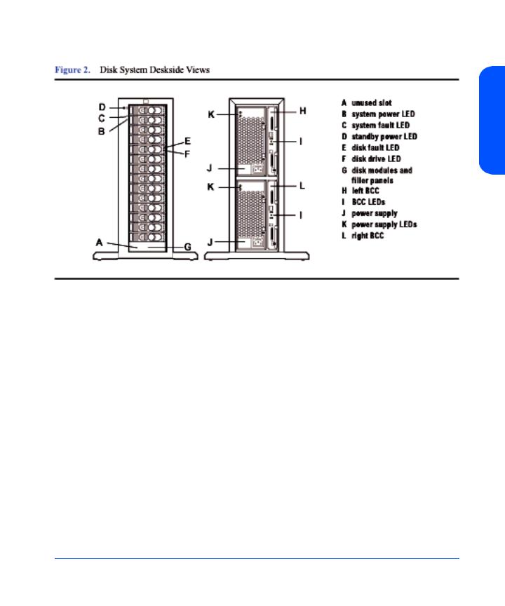
The disk system occupies 3 EIA units in a standard 19-inch rack. Disk drives mount in the front of the system. Redundant power supplies, and BCCs mount in the back. See Figure 1 and Figure 2 below. For disk slots and SCSI addressing, see Figure 49.
Description Product
Product Description 13

14 Product Description
Description Product
Status Indicators
LEDs on the disk system enable you to detect and replace failed components and so prevent or minimize users’ downtime. For additional information about LEDs, see Chapter 4, Troubleshooting.
On the front of the disk system, a pair of LEDs indicates the status of the disk system, and an LED for each slot shows disk I/O activity:
■The system power LED (B in Figure 1) indicates that power is on or off.
■The system fault LED (C in Figure 1) indicates whether or not a fault has occurred anywhere in the disk system.
■At the bottom of each disk module, the left LED (F in Figure 1) indicates the presence of I/O activity on the disk.
■The second LED on each disk module (E in Figure 1) can be flashed to help a customer engineer (CE) locate the disk for physical inspection or removal.
■The second LED is also used as a fault indicator for that specific disk module.
LEDs (I and K in Figure 2) on the back of the disk system indicate the status of replaceable components and the SCSI bus: See Chapter 4, Troubleshooting, for specific LED information.
Product Description 15

Power/Standby Switch
Located at the upper right corner of the front of the disk system, the power switch (D in Figure 1) interrupts DC power from the power supplies to the BCCs and other internal components. Input AC power to the power supplies is controlled by the power cords and the AC source.
High Availability
High availability is a general term describing computer systems that are designed to minimize planned and unplanned downtime. The disk system supports current systems’ high availability requirements through the following features:
■Hot-pluggable, high-capacity, high-speed disks
■Redundant, hot-pluggable, user-replaceable power supplies and BCCs
■Online firmware upgrades
■Hardware event monitoring and real-time error reporting
Clustering (NT)
The HP Disk System 2300 is Microsoft® Cluster certified for a variety of solutions. For specific information about supported configurations, see the Hewlett-Packard Company or Microsoft web pages:
http://hp.com
http://microsoft.com
Upgradability
You can increase disk system storage capacity by:
■Replacing disk drives with higher-capacity disk drives
■Adding disks in unused slots
None of these actions require shutting down the product, but some may require the use of system utilities to manage file systems.
Upgrade BCC and disk firmware using an on-line download function. See
Chapter 3, Updating Firmware.
16 Product Description

Environmental Services
Environmental services circuitry monitors the following elements:
■Fan rotation
■Power supply output
■Power supply status (fan status)
■Disk drive status, presence
■BCC status
■Temperature
■Self-test results
Each BCC reports the status of all elements in the disk system, even if the BCC does not have direct access to the element.
Additionally, the EEPROM on each BCC stores 2 Kbytes of configuration information and user-defined data, including the manufacturer serial number, and product number.
Hardware Event Monitoring
A hardware event monitor monitors the disk system and reports changes in environmental status to Hewlett-Packard’s Event Monitoring System (EMS) for HP-UX. Hardware event monitoring is an important tool for implementing high availability. Using hardware event monitors, you can virtually eliminate undetected hardware failures that interrupt system operation or cause data loss.
The EMS Hardware Monitors User’s Guide is available in Adobe® Acrobat® format on the HP document web site, http://www.docs.hp.com/hpux/systems/.
Description Product
Product Description 17

Components
User-replaceable components enable high availability and easy maintenance.
This section describes the following components:
■Disks and disk fillers
■BCCs and BCC fillers
■Power supply/fan modules
Disk Modules and Disk Module Filler Panels
Disk modules, shown in Figure 3, contain 3.5-inch Low Profile Ultra 3 LVD disks.
The disk module’s components are protected by a metal grill on the disk module’s bottom side.
WARNING Disks require careful handling and ESD precautions.
The plastic parts of the disk are safe to touch:
■Extractor handle (A in Figure 3)
■Latch tab (B)
You may also safely touch the top and bottom of the disk module without damaging the disk module.
A metal grill protects exposed circuits against damage when the disk module is laid circuit-side down on a flat surface.
The initial disk options for this product are 18-GByte, 36-GByte, and 73-Gbyte 10 K RPM disk drives. 18-GByte and 36-GByte 15 K RPM disk drives are also supported. A label on the disk carrier shows the storage capacity and rotational speed of the installed disk. Obtain information about the latest disk options from HP sales representatives.
Caution |
Fillers must be installed in unused slots in order to maintain even |
|
cooling for the installed disk modules. |
18 Product Description

Description Product
BCCs and BCC Filler Panels
BCCs (Bus Control Cards) plug into two slots in the back of the disk system. Each BCC connects to both LVD (low voltage differential) buses inside the disk system. In full bus mode (DIP switch 1 set to “|”), both BCCs have access to all installed disks. The two SCSI buses are bridged. If either BCC fails and LVM primary and alternate paths are defined, data can be accessed through the other BCC. In split bus mode (DIP switch 1 set to “0”), the left BCC (as viewed from the rear of the disk system), is on the high numbered bank (with disk slots 8, 9, 10, 11,12, 13, and 14) and the right BCC is on the low numbered bank (with disk slots 0, 1, 2, 3,4, 5, and 6) of disk slots. See Figure 1.
Two SCSI ports (B in Figure 4) on each BCC provide dual LVD connections to the same or separate hosts. If a host is connected to one of the BCC ports, an LVD terminator must be connected to the other port on that BCC.
Product Description 19
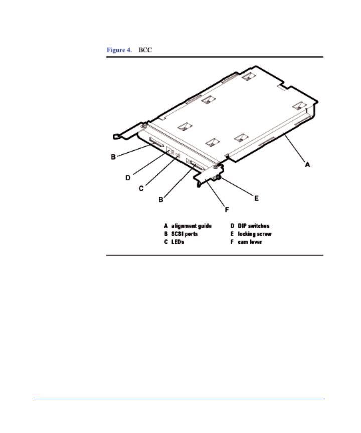
Other features of the BCC are:
■LEDs (C) indicating BCC status and bus configuration
■DIP switches (D) on the rear panel: 1 Bus Mode (full or split bus)
2 Monitor Mode (SAF-TE or SES)
■Locking thumbscrews (E)
■Cam levers (F)
20 Product Description
BCC circuitry provides the following functions:
■Bus configuration (see “Setting DIP Switches” in Chapter 3)
■Bus expansion (LVD)
■SCSI environmental services (see page 17)
■System fault detection
A BCC filler panel (Figure 5) replaces the second BCC when redundancy is not required.
Caution |
The BCC filler panel maintains even cooling inside the disk |
|
system when the second BCC is not present. A BCC filler panel |
|
must be installed if the BCC is removed. |
Description Product
Product Description 21

Power Supply/Fan Module
Redundant, hot-pluggable 340-watt power supplies convert wide-ranging AC voltage from an external main to stable DC output and deliver it to the midplane. Each power supply has an internal fan, an AC receptacle (A in Figure 6), two ejector handles (D) with thumbscrews (C), and 2 LEDs (B). Internal control prevents the rear DC output connector from becoming energized when the power supply is removed from the disk system.
22 Product Description

Power supplies share the load reciprocally; that is, each supply automatically increases its output to compensate for reduced output from the other, and vice versa. If one power supply fails, the other delivers the entire load.
Internal circuitry triggers a fault when the internal fan or other part fails. At the same time, the power fault LED (amber) illuminates, and, if enabled, the hardware event monitor sends an event message. The power supply fan remains on if other parts fail in order to maintain cooling air flow through the system. If the fan fails, the power supply shuts down. The fan in the other working power supply will increase to full speed to compensate for the failed fan. The failed power supply/fan module must be removed and the replacement power supply/ fan module installed within two minutes. In the event of a failure, if a replacement fan module/power supply is not available, leave the failed power supply/fan module installed until you are ready to replace it. This should be done to maintain proper cooling for the disk system.
Internal circuitry senses fan motion and triggers a fault when the speed of the power supply’s internal fan falls below a critical level. At the same time, the LED turns amber, and, if enabled, the hardware event monitor sends an event message.
Description Product
Product Description 23

Hardware/Software Requirements
The disk system is supported on the following operating systems:
■HP-UX 11.00 with HWE 0302 (March 2002 Patch bundles) or greater
■HP-UX 11.11 with HWE 0302 (March 2002 Patch bundles) or greater
■Linux Red Hat 6.2, 7.0, 7.1
■Windows NT 4.0 (Advanced Server, Enterprise Edition)
■Windows 2000 (Server and Advanced Server)
■Microsoft Windows.Net (Server and Advanced Server)
■SCO UnixWare 7.11
■SCO OpenServer 5.06
■HP MPE/iX 7.0
The following SCSI host bus adapters (HBAs) support the Disk System 2300:
■A4999A, Ultra2 Low Voltage Differential SCSI Host Bus Adapter for B-, C-, J-, and X-Class systems
■A5140A Single Port Ultra 2 SCSI HBA Host bus adapter for A-, L-, V-Class, and Superdome.
■A5149A, Single Port Ultra 2 SCSI HBA (PCI bus) Host bus adapter for rp54X0, rp7400, rp7410, and rp8400 servers and A-, N-, L-, V-Class, and Superdome systems (Full length card).
■A5150A, Dual Port Ultra 2 SCSI (PCI bus) Host bus adapter for rx4610 and rx9610 servers and A-, N-, L-, V-Class, and Superdome systems (Full length card).
■A5159A, Dual Part FWD SCSI PCI Host bus adapter for rx4610 and rx9610 servers
■A5838A, Dual-Port 100Base-T/Dual-Port Wide Ultra2 Host bus adapter for A-, N-, L-, V-Class, and Superdome systems.
■A5856A, RAID 4Si - 4-Port Ultra2 LVD/SE RAID Host bus adapter for rp54X0, rp7400, rp7410, and rp8400 servers, and A-, N-, L-, V-Class, and Superdome systems.
■A6828A, Single Port Ultra 160 SCSI HBA (PCI bus) Host bus adapter for rp54X0, rp7400, rp7410, and rp8400 servers, and A-, N-, L-, V-Class, and Superdome systems (Full length card).
24 Product Description

■A6829A, Dual Port Ultra160 SCSI (PCI bus) adapter Host bus adapter for rp54X0, rp7400, rp7410, and rp8400 servers and A-, N-, L-, V-Class, and Superdome systems (Full length card).
The following host bus adapters are supported on HP Netservers:
■C7430A, PCI Ultra2 wide Host bus adapter
■D5025A, HP Ultra/Wide SCSI Host bus adapter for Netservers
■D9161A, NetRAID 4M/64MB Cache Host bus adapter for HP Netservers
■D9351A, NetRAID 4M/128MB Cache Host bus adapter for HP Netservers
■P3413A, Single port Ultra160 SCSI Host bus adapter for HP Netservers
Description Product
Product Description 25

The following HP Netserver models are supported by the Disk System 2300:
■rc7100
■tc7100
■tc 6100
■tc4100
■tc3100
■rx4610
■LXr8000
■LXr8500
■LH3/LH3r
■LH4/LH4r
■LH3000/LH3000r
■LH6000/LH6000r
■LC2000/LC2000r
■LT6000
■LPr
■LP1000r
■LP2000r
■E45/E50
■E55/E60
■E200/E200se
■E800
The following host bust adapters are not supported at this time:
■D2140A, NetRAID 1Si Host bus adapter
■D5955A, NetRAID 3Si Host bus adapter
■P3410A, NetRAID 1M Ultra160 SCSI Host bus adapter with 64MB
■P3411A/B, NetRAID 2M Ultra160 SCSI Host bus adapter with 64MB
■P3475A/B, NetRAID 2M Ultra160 SCSI Host bus adapter with 128MB
26 Product Description

Topologies
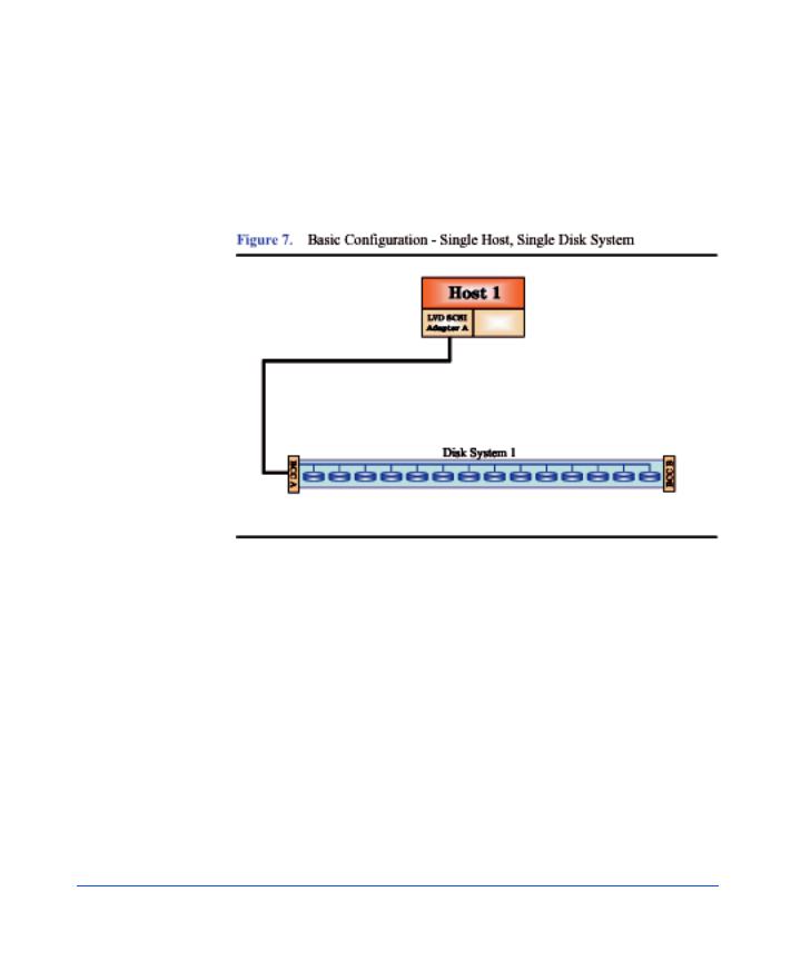
The disk system supports high availability through redundant components and redundant connections to redundant hosts. Each SCSI port on a BCC can be connected to a different host bus adapter in the same or different hosts. Internal mirroring within the disk system is also possible.
Basic high availability topologies are described on the following pages. For information about specific supported topologies, consult an HP sales representative.
This disk system can hold up to 14 disk modules. The maximum number of disk modules can be installed in either Full Bus Mode or Split Bus Mode. However, host and disk drive addressing must be closely managed.
Full Bus Mode
The maximum of 14 disk modules can be supported in Full Bus Mode provided there there is only one host bus adapter (HBA) connection and the HBA has the SCSI address of 7.
If more than one host connection is required, the slot with the SCSI address corresponding to the SCSI address of the additional host must not have a disk module installed in it to avoid bus contention. For example, if two connections are made to a Disk System 2300 with HBAs having SCSI addresses of 6 and 7, then SCSI ID 6 (slot 7)must not have a disk module installed in it.
Note |
SCSI address 15 should never be used by an HBA when |
|
connecting to a Disk System 2300 because this address is reserved |
|
on the SCSI bus for the enclosure services microprocessor. |
Connecting one disk system to redundant hosts achieves system level high availability. A single host bus adapter in each host is connected to a different port in the disk system. With the disk system in full bus mode (switch 1 on), each host can reach all the disks. If the right BCC (viewed from the rear of the disk system) fails in this topology, there is still one path to the disks through BCC B. With the disk system in split bus mode (two internal busses), the Disk System 2300 supports data mirroring between the two internal busses within the same disk system. All connections from the host to the disk system are SCSI LVD cables.
Description Product
Product Description 27
Another type of high availability topology connects mirrored disk systems to redundant hosts. Dual host bus adapters in each host are connected to mirrored disk systems. With the disk systems in full bus mode (switch 1 on), each host can reach all disks in both disk systems. If one of the disk systems fails in this topology, all hosts will still have access to the data on the mirrored disk system. All connections from the host to the disk system are SCSI LVD cables.
Due to SCSI ID limitations, daisy chaining of the Disk System 2300 is not supported. The maximum storage capacity with this type of configuration is approximately one Terabyte. This configuration does not provide any redundant paths to the data, however there is some hardware redundancy provided by the disk system hardware (i.e. power supply/fan modules and BCCs). This configuration can be used for boot, root, swap, or file system storage. Using Mirror/UX software, one or more mirrors can be created on the same hardware path to provide a basic level of data protection.
In figures 7 through 11, any BCC shown with only one cable connection should be understood to have a terminator attached to the other SCSI connector.
28 Product Description

Description Product
The disk system can be connected to a single host with two host bus adapters (HBAs) in a split bus configuration. See Figure 8. Each HBA will do reads and writes to a maximum of seven disks. This configuration can provide a maximum capacity of approximately 1.1 Terabytes. This configuration can also do basic mirroring across different hardware paths, still providing a maximum data capacity of approximately 0.5 Terabytes. This configuration can also yield a maximum performance of 320 MB/s, since each BCC card is capable of 160MB/ s performance in a split bus mode.
Product Description 29
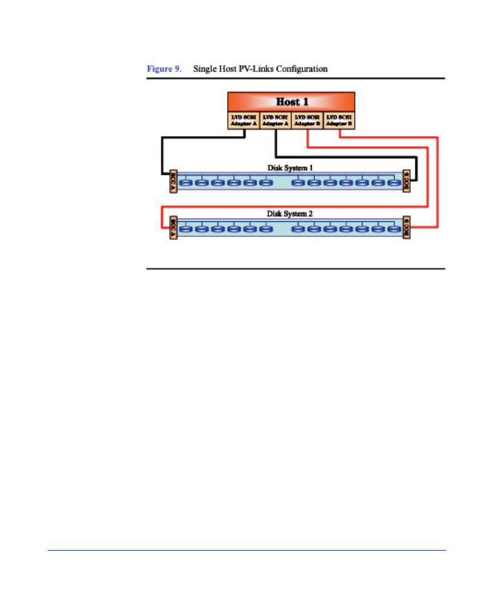
Data path redundancy can be secured with the configuration shown in Figure 9. Using an additional host bus adapter (HBA) and the LVM software, alternate links can be created, providing a redundant path to data for each disk system. In addition, a separate mirror path can be created for data protection. This configuration provides protection against any single component failure (i.e., cables, HBAs, disks). Figure 9 depicts connecting two disk systems to a single host.
The only limit on the number of disk systems per system is the maximum number of supported HBAs. For large configuration, it is recommended that multiple CPUs have large amounts of memory to handle the system load. Each disk system in this configuration is capable of 160MB/s performance. Due to SCSI ID limitations, a maximum of 13 disks is supported per disk system (13 disks + 2 HBAs + 1 SES = 16 SCSI IDs).
30 Product Description
Loading...